Sign In
Upload
Manuals
Brands
Woodward Manuals
Controller
2301E
Woodward 2301E Manuals
Manuals and User Guides for Woodward 2301E. We have
1
Woodward 2301E manual available for free PDF download: Installation And Operation Manual
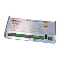
Woodward 2301E Installation And Operation Manual (182 pages)
Digital Load Sharing and Speed Control for Engines
Brand:
Woodward
| Category:
Controller
| Size: 4.96 MB
Table of Contents
Table of Contents
3
Warnings and Notices
7
Electrostatic Discharge Awareness
8
Regulatory Compliance
9
Chapter 1. General Information
11
Description
11
Applications
12
Control Options
13
References
13
Figure 1-1A. 2301E Outline Drawing (Ordinary Locations)
14
Figure 1-1B. 2301E Outline Drawing (Hazardous Locations)
15
Figure 1-2A. 2301E Control Wiring Diagram (Sheet 1)
16
Figure 1-2B. 2301E Control Wiring Diagram (Sheet 2)
17
Figure 1-2C. 2301E Control Wiring Diagram (Notes)
18
Chapter 2. Installation
19
Introduction
19
Unpacking
19
Power Requirements
19
Location Considerations
20
Electrical Connections
20
Shields and Grounding
21
LED System Status Indicators
21
Figure 2-1. Installation of Wiring into Terminal
21
Setting Speed Range
22
Potential Transformer Connections (Terminals 1-3)
22
Current Transformer Connections (Terminals 4-9)
22
Real Power Load Calculation
22
Load Share Lines (Terminals 10-12)
22
Power Supply (Terminals 48-50)
23
Discrete Inputs (Terminals 34-41)
24
Close to Run or Minimum Fuel (Terminal 34)
25
Discrete Inputs B, C, D (Terminals 35, 36, 37)
25
Failed Speed Override
26
Reset
26
Select 2 Nd Dynamics
26
Shutdown External
26
Idle / Rated Speed
27
Idle/Rated Software Switch
27
CB Aux/Droop Contact
27
Derate KW Load Reference
28
50 / 60 Hertz Operation
28
Raise Speed/Load Contact (Terminal 38)
28
Figure 2-2. Droop Contact and Circuit Breaker Auxiliary Contact
28
Lower Speed/Load Contact (Terminal 39)
29
Remote Speed Setting (both Raise and Lower Contacts; Terminals 38 and 39)
29
Load Generator (Terminal 40)
30
Base Load (Terminal 41)
30
Actuator Output (Terminals 13-15)
30
Analog Inputs (Terminals 19-24)
30
Analog Input #1 (Terminals 19-20)
32
Analog Input #2 (Terminals 22-23)
32
Speed Sensor (Terminals 25-26)
33
Relay Driver Outputs (Terminals 42, 43, & 44-48)
33
Ma Output (Terminals 16-17)
34
Communication Ports
34
Figure 2-3. RS-232 Pin Assignments for Serial Communication Cable
35
Figure 2-4. Typical RS-422 Communications Connections
35
Figure 2-5. RS-422 Terminator Locations
36
Figure 2-6. Preferred Multipoint Wiring Using Shielded Twisted-Pair Cable with a Separate Signal Ground Wire
37
Figure 2-7. Alternate Multipoint Wiring Using Shielded Twisted-Pair Cable Without a Separate Signal Ground Wire
37
Installation Check-Out Procedure
38
Chapter 3. Description of Operation
39
Introduction
39
Speed Control
39
Control Dynamics
40
Figure 3-1. Speed Control System
40
Minimum Fuel Function
41
Maximum Fuel Function
42
Start Fuel Limit Function
42
Figure 3-2. Start Limit Function
42
Torque Limiter
43
Manifold Air Pressure Limiter
43
Speed/Load Reference and Ramps
43
Figure 3-3. Dual Start Limit Function
43
Speed Reference and Ramp Functions
44
Figure 3-3. Remote Speed Reference
45
Speed Bias and Synchronizer Summing
46
Load Reference and Ramp Functions
46
Droop Function
48
Figure 3-4. Paralleling System
49
Figure 3-5. Droop Mode
50
Figure 3-6. Isochronous Mode
51
Droop/Isochronous Load Sharing on an Isolated Bus
52
Figure 3-7. Droop/Isochronous Load Sharing
52
Figure 3-8. Isochronous Load Sharing
52
Isochronous Load Sharing on an Isolated Bus
53
Actuator Droop
53
Load Pulse / Load Rejection
53
Figure 3-9. Load Pulse / Rejection
54
Chapter 4. Entering Control Set Points
56
Introduction
56
Control Assistant PC Interface
56
Control Assistant Features
56
System Requirements
57
Acquiring Control Assistant and the SOS Servlink OPC Server Software
57
Figure 4-1. Null Modem Cable
58
2301E Toolkit Service Tool
68
Figure 4-1. Null Modem Cable
68
Entering the Configure Mode
81
Configure Menu Descriptions
81
Exiting the Configure Mode
90
Service Menu Descriptions
90
Figure 4-2. Control Gain as a Function of Speed Error
97
Figure 4-3. Control Gain as a Function of Fuel Demand (Load)
98
Figure 4-4. Speed Filter
99
Figure 4-5. Typical Transient Response Curves
100
Figure 4-6. Non-Linear Valve Power Curve
105
Figure 4-7. Non-Linear Valve Power Curve for Turbocharged Engine
105
Figure 4-8. Linearized Gain Plot
106
Figure 4-9. Start Limit Function
108
Figure 4-10. Soft Start Fuel Limit Function
109
Figure 4-11. Torque Limiter Function
111
Figure 4-12. Dual Start Fuel Limit with Ramp
111
Figure 4-13. MAP Limiter Function
113
Saving the Tunable Values
126
Chapter 5. Initial Control Settings
127
Initial Prestart Settings
127
Start-Up Adjustments
127
Adjust for Stable Operation
128
Dynamic Adjustment
129
Actuator Compensation Adjustment
129
Ramp Time Adjustment
129
Raise/Lower Time Adjustment
129
Start Fuel Limit Adjustment
130
Speed Sensor Check
130
Current Transformer (CT) Phasing Check
130
Phase Correction Procedure
131
Figure 5-1. Temporary Wiring for Transformer Phase Correction
132
Load Calibration Adjustment
134
Droop Adjustment
134
Figure 5-2. Droop Adjustment
134
Chapter 6. Alternate Dynamic Adjustments
135
Introduction
135
Adjustment
135
Figure 6-1. Trend Tool Trace Example 1
136
Figure 6-2. Trend Tool Trace Example 2
137
Figure 6-3. Trend Tool Trace Example 3
137
Figure 6-4. Trend Tool Trace Example 4
138
Figure 6-5. Trend Tool Trace Example 5
138
Figure 6-6. Trend Tool Trace Example 6
138
Chapter 7. Troubleshooting
140
Introduction
140
Troubleshooting Procedure
140
Control Start-Up
140
Control Test and Calibration
141
Troubleshooting Charts
142
Chapter 8. Communications
147
Modbus Communication
147
Monitor Only
147
Monitor and Control
147
Modbus Communication Mode
148
Modbus Function Codes
149
Port Adjustments
149
2301E Control Modbus Addresses
150
Modbus Scale Factors
151
Shutdown Command through Modbus
151
Start Command through Modbus
152
For more Modbus Information
152
Chapter 9. Product Support and Service Options
153
Product Support Options
153
Product Service Options
153
Returning Equipment for Repair
154
Replacement Parts
154
Engineering Services
155
Contacting Woodward's Support Organization
155
Technical Assistance
156
Appendix A. Service/Configuration Chart
157
Configure Menus
157
Service Menus
158
Pid Examples
165
PID Conversion Charts
166
Figure B-1. Gain Potentiometer Conversion Chart
166
Figure B-2. Reset Potentiometer Conversion Chart
166
Figure B-3. Actuator Compensation Potentiometer Conversion Chart
167
Appendix C. Modbus Communication List
168
Appendix D. Software Revision
171
Appendix E. Printing out a Datalog
174
Appendix F. Quick Engine Start Guide
175
Figure E-1. Location of "First Time Configuration Wizard" Button
175
Appendix G. Loading the Settings File from a 2301D to a 2301E
176
Appendix H. Connecting a 2301E to Control Acat Adem Control in the Direct Rack Mode
178
2301E Control Specifications
179
Revision History
180
Manual
180
Declarations
181
Advertisement
Advertisement
Related Products
Woodward 2301A
Woodward PGA-EG 200
Woodward 2301D
Woodward 2301D-EC
Woodward 2301
Woodward 2301E-HT
Woodward 2370ES
Woodward 2301E-ST
Woodward 2300E
Woodward ProTech 203
Woodward Categories
Controller
Control Unit
Relays
Control Systems
Industrial Equipment
More Woodward Manuals
Login
Sign In
OR
Sign in with Facebook
Sign in with Google
Upload manual
Upload from disk
Upload from URL