Sign In
Upload
Manuals
Brands
Woodward Manuals
Control Systems
Vertex-Pro
User Manuals: Woodward Vertex-Pro Compressor Control
Manuals and User Guides for Woodward Vertex-Pro Compressor Control. We have
1
Woodward Vertex-Pro Compressor Control manual available for free PDF download: Installation/Hardware Manual
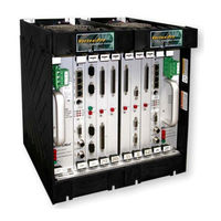
Woodward Vertex-Pro Installation/Hardware Manual (112 pages)
Motor-Driven Compressor Control
Brand:
Woodward
| Category:
Control Systems
| Size: 2 MB
Table of Contents
Table of Contents
3
Regulatory Compliance
6
Electrostatic Discharge Awareness
9
Chapter 1. General Information
11
Introduction
11
Specifications and Compatibility
11
Chapter 2. Vertex-Pro Systems
12
Vertex-Pro Configurations
12
Vertex-Pro Redundant
13
Figure 2-1-Input Flow
14
Figure 2-2-Output Flow
14
Figure 2-3-Redundant Sensors
14
Vertex-Pro Redundant Operation
15
Vertex-Pro Simplex
16
Figure 2-4-Input Flow
17
Figure 2-5-Output Flow
17
Figure 2-6-Redundant Sensors
17
Vertex-Pro Simplex Operation
18
Module Replacement
18
Latent Fault Detection
18
Figure 2-7-CHAS_STAT Block
19
Chapter 3. Chassis
20
Micronet Plus 8-Slot Chassis
20
Figure 3-1-Micronet Plus 8-Slot I/O Chassis
20
Specification
21
Figure 3-2-Micronet Plus 8-Slot Chassis
21
Installation
23
Figure 3-3-Outline Drawing of Micronet Plus 8-Slot Chassis
23
Figure 3-4-Mounting Template of Micronet Plus 8-Slot I/O Chassis
23
Chapter 4. Power Supplies
24
Vertex-Pro Chassis Power Supplies
24
Figure 4-1-Power Supply Module
25
Installation
26
Table 4-1—Micronet Plus Power Supply Requirements
27
Power Supply Troubleshooting
28
Chapter 5. CPU
30
Figure 5-1-CPU Module
31
Figure 5-2-CPU Module Block Diagram
31
Figure 5-3-CPU Communications Port (DB9F)
35
Figure 5-4-RS-422 Terminator Locations
35
Figure 5-5-RS-485 Terminator Locations
36
Figure 5-6-Termination and Cable Connection Examples
36
Figure 5-7-Preferred Multipoint Wiring Using Shielded Twisted-Pair Cable with a Separate Signal Ground Wire
37
Figure 5-8-Alternate Multipoint Wiring Using Shielded Twisted-Pair Cable Without a Separate Signal Ground Wire
37
Figure 5-9-CPU Service Port (Mini-DIN6F)
38
Figure 5-10-CAN Communication Ports (M12 Male)
38
Figure 5-11-CAN Communication Connection Example
39
Cpus
30
Powerpc CPU5200 Module (Motorola)
30
Chapter 6. Discrete I/O Modules
41
Introduction
41
48/24 Discrete Combo Module
41
Figure 6-1-Discrete Combo Module
42
Figure 6-2-Configuration 2, Two 24/12 Discrete Ftms
43
Figure 6-3-Discrete Input Interface Wiring to a 24/12 Discrete FTM
44
Figure 6-4-Relay Output Interface Wiring to a 24/12 Discrete FTM
45
Figure 6-5-48/24 Discrete Combo Module Block Diagram
46
Chapter 7. Analog I/O Modules
48
Introduction
48
Combination I/O Modules
48
24/8 Analog Module
48
Figure 7-1-24/8 Analog Module
49
Figure 7-2-Simplex System Configuration Example
51
Figure 7-3-Analog Input Wiring for a 24/8 Analog FTM
52
Figure 7-4-Analog Output Wiring for a 24/8 Analog FTM
53
Analog Combo Module (Option)
56
Figure 7-5-Analog Combo Module
56
Figure 7-6-Simplex System Configuration Example
59
Figure 7-7-Mpu/Proximity Interface Wiring to the Analog Combo FTM
60
Figure 7-8-Current Input Wiring for an Analog Combo Module FTM
62
Figure 7-9-Voltage Input Wiring for an Analog Combo Module FTM
63
Figure 7-10-Analog Output and Actuator Wiring for an Analog Combo FTM
65
Chapter 8. Field Termination Modules (Ftms)
70
Introduction
70
Analog I/O Ftms
70
Figure 8-1-24/8 Analog FTM Outline Dimensions
71
Figure 8-2-24/8 Analog FTM Schematic
72
Figure 8-3-Analog Combo FTM Outline Dimensions
73
Figure 8-4-Analog Combo FTM Schematic
74
Discrete I/O FTM
75
Figure 8-5-24/12 Discrete Module Outline Dimensions
76
Figure 8-6-24/12 Discrete Module Schematic
77
Chapter 9. Installation and Replacement Procedures
78
Pre-Installation Information
78
Installation Procedures
79
Figure 9-1-Micronet Power Supply
80
Figure 9-2-FTM Grounding and Outlines
82
Figure 9-3-Shield Termination Diagram Example
83
Figure 9-4-Discrete FTM Grounding Diagram Example
83
Figure 9-5-Bottom Cable Entry Area
88
Figure 9-6-Door Bonding
88
Figure 9-7A-Cable Entry # 1
89
Figure 9-7B-Cable Entry # 2
89
Replacement Procedures
90
Figure 9-8-Zoning
90
Chapter 10. Service Options
96
Product Service Options
96
Woodward Factory Servicing Options
97
Returning Equipment for Repair
98
Replacement Parts
98
Engineering Services
99
How to Contact Woodward
99
Technical Assistance
100
Appendix A. Matrix of Modules with Compliance Information
101
Appendix B. Environmental Specifications
102
Appendix C. Declarations
103
Appendix D. Acronyms
108
Advertisement
Advertisement
Related Products
Woodward Vertex
Woodward VariStroke-I
Woodward VariStroke-DX
Woodward VS-I
Woodward 1907
Woodward 2301E-HT
Woodward 505E
Woodward 505HT
Woodward Categories
Controller
Control Unit
Relays
Control Systems
Industrial Equipment
More Woodward Manuals
Login
Sign In
OR
Sign in with Facebook
Sign in with Google
Upload manual
Upload from disk
Upload from URL