
Related Manuals for Wintriss wpc 2000


Summary of Contents for Wintriss wpc 2000
- Page 1 WPC 2000 Wintriss Clutch/Brake Control 1128500 Rev. P November 2015 Tech Support Hotline 800-586-8324 8-5 EST Wintriss Controls Group, LLC www.wintriss.com...
- Page 2 1910.217 (b) (7). Refer also to ANSI B11.1-2009. Use WPC 2000 clutch/brake control only on rotating machinery that can be stopped at any point in its stroke or cycle. Failure to comply with these instructions will result in death or serious injury.
- Page 3 Ensure that the press on which WPC 2000 clutch/brake control is used meets the machine guarding requirements of OSHA standard 1910.217 and any other regulations and standards that apply. DO NOT operate a press equipped with WPC 2000 clutch/brake control if the machine or any of its stopping mechanisms is not in proper working order.
-
Page 4: Wpc 2000 User Manual
Changes for Revision P of the WPC 2000 User Manual (1128500) This revision of the WPC 2000 user manual covers WPC 2000 software version 6.00 and higher. The changes include: Revised mounting dimensions for the WPC 2000 enclosure (see page 2-7) - Page 5 Wintriss Product. We appreciate your business and want to do whatever we can to ensure your satisfaction. Wintriss products are built to stay on the job day after day, and are backed by an ironclad guarantee, international standards approvals, and unbeatable support.
-
Page 6: Table Of Contents
WPC 2000 Components ........ - Page 7 Mounting a One-hand Control ........2-44 Wiring a One-hand Control to WPC 2000 ....... 2-45 Mounting and Wiring the Bar Control Enclosure .
- Page 8 WPC 2000 User Manual 1128500 Wiring Tables ..........2-61 Chapter 3.
- Page 9 1128500 WPC 2000 User Manual Checking the Top-stop Circuit ........3-40 Checking for Faults When the Press Is Running .
- Page 10 Responding to WPC 2000 Faults ........5-2...
- Page 11 Figure 2-5. AC Input Wiring Connections ..................2-8 Figure 2-6. Pre-wired Operator Stations Showing Mute Lamp Connections ........ 2-13 Figure 2-7. Wiring Steps to Modify Operator Station for WPC 2000 ........... 2-14 Figure 2-8. Pre-wired Operator Station with Side Run Buttons: Mounting Dimensions ....2-15 Figure 2-9.
- Page 12 Figure 5-3. WPC 2000 Display Showing Stopping Time Fault ............5-4 Figure 5-4. Ross DM2 DSV Showing Reset Button ...............5-22 Figure C-1. Option 1 Board Installed on WPC 2000 Main Processor Board ........C-4 Figure C-2. WPC 2000 Option 1 Board ................... C-5 Figure C-3.
- Page 13 Table 2-24. AC Power Wiring ........... . . 2-63 Table 3-1. WPC 2000 Display: Default Parameters (Press Running) ..... . . 3-2 Table 3-2.
- Page 14 1128500 Table C-2. WPC 2000 Option 1 Board: Wiring Connections, TB601 ..... . C-6 Table C-3. WPC 2000 Option 1 Board: Wiring Connections, TB602 ..... . C-6 Table C-4.
- Page 15 Chapter 3 shows you how to initialize and set up WPC 2000 and perform final checkout tests. Chapter 4 shows you how to run the press, using WPC 2000’s Inch, Single-stroke, and Continuous stroke selections and Two-hand, One-hand, and Foot modes.
- Page 16 WPC 2000 User Manual 1128500 Important Highlighted Information Important danger, warning, caution and notice information is highlighted throughout the manual as follows: DANGER A DANGER symbol indicates an imminently hazardous situation, which, if not avoided, will result in death or serious injury.
- Page 17 Wintriss Controls freight prepaid and which are, after examination, disclosed to the satisfaction of Wintriss to be defective. This warranty shall not apply to any equipment which has been subjected to improper installation, misuse, misapplication, negligence, accident, or unauthorized modification.
-
Page 18: Introduction
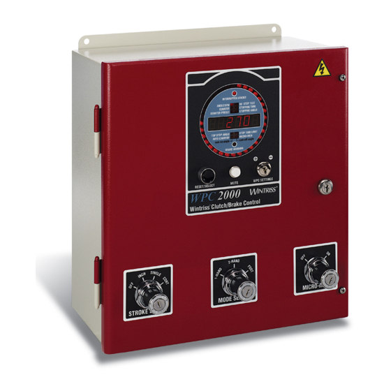
WPC 2000 can be shared with other Wintriss resolver-based products, such as DiPro 1500. Control Enclosure The WPC 2000 control enclosure (see Figure 1-1, page 1-2) can be ordered with the display and controls mounted on the front (center mount) or on the left (left mount) or right side (right mount). -
Page 19: Figure 1-1. Wpc 2000 Control Enclosure And Display
AUTO CARRYUP MICRO-INCH cam on angle cam off angle BRAKE WARNING RESET/SELECT MUTE WPC SETTINGS WPC 2000 Wintriss ® Clutch/Brake Control STROKE SELECT STROKE SELECT MODE SELECT MICRO-INCH OP STN AUTOMATIC Figure 1-1. WPC 2000 Control Enclosure and Display Introduction... -
Page 20: Operator Station
The Operator Station is normally the device used to run the press in all Stroke Select positions. Wintriss provides operator stations with Run/Inch palm switches mounted on either the top or sides (see Installing Operator Station(s), page 2-12 for available configurations). Figure 1-2 shows the switches and indicator lamps on an Operator Station with side-mounted Run/Inch palm switches. -
Page 21: Other Components
Foot Switch or in One-hand operating mode. Multiple light curtains can be wired to a WPC 2000. WPC 2000 tests up to two pairs of Shadow inputs every time that the press is started and stopped. See Installing a Light Curtain, page 2-18 for more information. -
Page 22: Standard Features
Top-stop. When the press’s stopping time is within ten milliseconds of the preset Stop-time Limit, the Brake Warning LED flashes. When the stopping time exceeds the Stop-time Limit, WPC 2000 issues a Stop command to the press and prevents the press from being restarted until the brake has been serviced. -
Page 23: Optional Features
When the count total reaches the value set on the Counter Preset indicator segment (see page 4-6), WPC 2000 stops the press. The counter is reset to “1” with the Reset/Select button. The counter preset feature is useful for batch sizing or periodic QC checks. - Page 24 Compensated Top Stop (ACTS), page 3-28 for additional information about this feature. Multiple Operator Stations–Two Operator Stations can be connected directly to WPC • 2000. If you wish to install more than two Op. Stations, contact Wintriss Tech. Support (see Installing Multiple Operator Stations, page 2-17). DANGER HAZARDS EXPOSED BY NON-WORKING OPERATOR STATION •...
-
Page 25: Specifications
1128500 WPC 2000 User Manual Specifications WPC 2000 specifications are shown in Table 1-1. Table 1-1. WPC 2000 Specifications Control Enclosure: 14.00 x 19.62 x 7.00 in. (355.6 x 498.3 x 177.8 mm), NEMA 12, shock-mounted. Panel Mount: 7.50 x 10.00 in. (190.5 x 254.0 mm) - Page 26 Diagnostic LEDs on Main Processor board for power and for all inputs, including buttons and switches. Presettable Counter Counts number of strokes; can be used to stop the press for batch sizing or QC checks. Includes 6-digit counter on front panel of WPC 2000. Introduction...
- Page 27 Bar Mode Control Allows manual turning of crankshaft. Motor Control and Custom Packages Refer to Press Control/Motor Starter literature, and/or contact your Wintriss representative or factory for more details. Option 1 User Inputs Provides 20 additional non-control-reliable inputs and 4 additional control- reliable, cross-checked input pairs for customized status codes.
-
Page 28: Chapter 2. Installation
• Follow all procedures in this manual. Perform only the tests and repairs listed in this manual. Use only factory-supplied replacement parts. • Ensure that WPC 2000 clutch/brake control is installed, tested and repaired by qualified personnel. • Wire, install and maintain WPC 2000 clutch/brake control in accordance with the applicable safety standards. - Page 29 NOTICE READ INSTALLATION INSTRUCTIONS BEFORE STARTING INSTALLATION If you install WPC 2000 yourself, read this installation chapter carefully and plan how you are going to proceed before you start drilling holes, running conduit, or cutting wires. Make sure you are familiar with the WPC 2000 display (see page 1-2). If you encounter problems during installation, contact Wintriss Tech.
-
Page 30: Installation Guidelines
Run one or two low-voltage conduits for the resolver wires to the knockouts on the bottom • of the WPC 2000 enclosure. Because WPC 2000 is rated NEMA 12 (protected against dust and oil), you must use • conduit of the same rating and make proper connections to ensure NEMA 12 protection. -
Page 31: Figure 2-1. Wpc 2000 Wiring Overview
1128500 WPC 2000 User Manual Motor Control Wintriss Clutch/brake Control Operator Station Figure 2-1. WPC 2000 Wiring Overview Installation... -
Page 32: Connecting Wires To Terminal Block Connectors
Perform the following steps to terminate shielded cables to the ground studs located inside the WPC 2000 enclosure near the cable’s point of entry, referring to Figure 2-3, page 2-6. Strip the cable jacket as far as the end of the conduit fitting. -
Page 33: Mounting The Control Enclosure
Motor reverse auxiliary contact (24V), if applicable • Power to WPC 2000 should be provided by a step-down control transformer capable of handling 75 VA at 115 Vac ± 10%. Most of the original controls on the press will be replaced during rewiring except the disconnect, motor starter, and control transformer. -
Page 34: Slide Adjust Considerations
WPC 2000 User Manual 1128500 NOTICE NON-ENCLOSURE INSTALLATION See Installing WPC 2000 without Enclosure, page 2-51 for installation instructions if you are installing WPC 2000 in your own enclosure or console. Figure 2-4. WPC 2000 Enclosure: Mounting Dimensions Slide Adjust Considerations If your press has a motorized slide adjustment for the ram, you must prevent slide adjustment while the press is running. -
Page 35: Connecting Ac Wiring
1128500 WPC 2000 User Manual Connecting AC Wiring DANGER ELECTRIC SHOCK OR HAZARDOUS ENERGY • Disconnect main power before installation. • Remove all power to the press, press control, and other equipment used with the press. • Remove all fuses and “tag out” per OSHA 1910.147 Control of Hazardous Energy (Lockout/ Tagout). -
Page 36: Installing A Dual Safety Valve
1128500 NOTICE WPC 2000 AUTOMATICALLY ADJUSTS TO 115 OR 230 VOLT INPUT POWER You do not need to use a switch or other device to set the level of input power. To make AC power wiring connections, perform the following steps: Locate the power supply input terminal block on the back wall at the top left of the enclosure, as shown in Figure 2-5. - Page 37 Connect all signal grounds through pins on the WPC 2000 Main Processor board. If you have ordered a Ross or Herion DSV with your WPC 2000, refer to the appropriate wiring diagram at the end of this manual and to the documentation that came with your valve to install the DSV.
-
Page 38: Installing Air Pressure Switches
Failure to comply with these instructions could result in property damage. Note that the DM2 Reset circuit is wired to the OFF position on the WPC 2000 Stroke Select switch (see Figure 6). To reset the Ross DM2 DSV after an F47 error (see page 5-12), press Reset/Select, and turn the Stroke Select switch to OFF, then back to one of the other operating modes (i.e., Inch, Single-stroke, or Continuous). -
Page 39: Installing A Counterbalance Air Pressure Switch
If pin #83 has already been assigned to other user-selected auxiliary equipment, then wire the counterbalance switch contacts across a terminal on the WPC 2000 Main Processor board that generates an E-stop when the connection to ground is broken. See Wiring WPC 2000 User Inputs, page 2-28 for more information. -
Page 40: Wiring A Pre-Wired Operator Station
Wiring a Pre-wired Operator Station Checking Pre-wired Operator Station Wiring Before connecting your pre-wired Operator Station to WPC 2000, check the wiring to the mute lamp inside the Operator Station and modify, if necessary, according to the instructions below. Operator stations shipped as part of WPC 2000 systems should not need modification. -
Page 41: Figure 2-7. Wiring Steps To Modify Operator Station For Wpc 2000
If your mute lamp wiring looks like panel “A”, follow steps A through E in Figure 2-7 • to disconnect the white-and-red wires and connect the black wire. When the mute lamp wiring is correct, connect the Operator Station to WPC 2000. Figure 2-7. Wiring Steps to Modify Operator Station for WPC 2000 2-14... -
Page 42: Making Wiring Connections
WPC 2000 User Manual 1128500 Making Wiring Connections To wire a pre-wired Operator Station, perform the following steps: Punch a hole in the Operator Station enclosure for conduit or sealtight. Connect the conduit or sealtight to the hole; then open the Operator Station box. -
Page 43: Wiring An Unwired Operator Station
Failure to comply with these instructions will result in death or serious injury. To wire the unwired Wintriss Operator Station, follow the wiring diagram in Figure 7 at the end of this manual. Before using your press, be sure to check the wiring carefully, run all the applicable verification and checkout tests, and calculate the safety distance. -
Page 44: Wiring A User-Built Operator Station
Use light curtains in addition to multiple Operator Stations for best personnel safeguarding. You can wire up to two Operator Stations to the WPC 2000 (see Figure 4 at the back of the manual for dual Op. Station wiring). Make sure that switch 6 on S102 on the WPC 2000 Main Processor board is set to OFF if you connect dual Operator Stations (see page 3-33). -
Page 45: Installing A Light Curtain
3-19. NOTICE You cannot permanently mount the light curtain until the WPC 2000 is working properly and you have measured the Stopping Time, set the brake monitor, and calculated the correct safety distance. However, you will be able to wire the light curtain. -
Page 46: Installing Shadow Light Curtains
WPC 2000 User Manual 1128500 WPC 2000 provides wiring connections for up to two pairs of light curtains (see Table 2-17, page 2-62). If you wire two sets of light curtains, you must enable them on S101 option switch 6 (see Table 3-9, page 3-29). -
Page 47: Installing The Resolver
1128500 WPC 2000 User Manual If you plan to interface a light curtain system other than Shadow with your WPC 2000, please call Wintriss Tech. Support for instructions. Be ready to provide the following information: Light curtain manufacturer • Light curtain model number •... -
Page 48: Mounting The Resolver
WPC 2000 User Manual 1128500 Do not try to couple the resolver directly to the crankshaft. Such a placement requires • extreme precision. If the resolver is only slightly off-center, its bearing will be subjected to side loads well in excess of its rated capacity and will ultimately fail. -
Page 49: Wiring The Resolver
Find the resolver terminal block, TB 106, on the WPC 2000 Main Processor board (see Figure 2-12, page 2-23 or Figure 2-13, page 2-24), and remove the L-shaped connector. -
Page 50: Important Components
WPC 2000 User Manual 1128500 LED # Figure 2-12. WPC 2000 Main Processor Board (Right or Center Configuration): Location of Important Components Installation 2-23... - Page 51 1128500 WPC 2000 User Manual LED # Figure 2-13. WPC 2000 Main Processor Board (Left Configuration): Location of Important Components 2-24 Installation...
-
Page 52: Checking The Resolver's Direction Of Rotation
WPC 2000 at the same resolver angle on every stroke. Whenever this angle changes, WPC 2000 detects that the resolver is no longer rotating at a 1:1 ratio with the crankshaft and sends an Emergency-stop command to the press, simultaneously displaying an error code. -
Page 53: Planning Your Overrun Sensor Installation
1128500 WPC 2000 User Manual Planning Your Overrun Sensor Installation The overrun sensor consists of a magnetic switch and a magnet. Select a mounting location for both components that ensures that the magnet moves past the switch once on every stroke and within 1/8 in. -
Page 54: Wiring The Overrun Sensor Switch
If you do so, wait to cut the cable and wires until both the resolver and the overrun limit sensor are installed. Run the cable for the magnetic switch through conduit to the WPC 2000. Connect the wires to terminal blocks on the WPC 2000 Main Processor board, as shown in Table 2-2 and Figure 2 at the end of the manual. -
Page 55: Wiring Wpc 2000 User Inputs
CHECK PRESS TO MAKE SURE IT STOPS WHEN USER INPUT ACTUATES • WPC 2000 comes from the factory with the inputs bypassed by jumpers. Make sure to remove the appropriate jumper from the Main Processor board connector when you wire a user input. -
Page 56: Table 2-3. Wpc 2000 User Inputs: Stop Types, Fault Codes, And Wiring Connections
WPC 2000 User Manual 1128500 Table 2-3. WPC 2000 User Inputs: Stop Types, Fault Codes, and Wiring Connections Jumper User Input Connection Fault Name of Auxiliary (Interlock) Stop Type (Bypass) Code Equipment User 1 ESTOP +24 Vdc User 2 ESTOP... -
Page 57: Wiring The Lockout Relay
WPC 2000 by purchasing the Option 1 “daughter” board, which you install on the WPC 2000 Main Processor board. If you are interested in this product, contact your local Wintriss representative or call Wintriss Tech. Support. To install, wire, and troubleshoot the Option 1 board, refer to Appendix C. -
Page 58: Auxiliary Output 1
Output turns OFF when an Interrupted Stroke occurs Output remains ON during an Interrupted Stroke unless the Interrupted Stroke is preceded by a WPC 2000 fault or an Emergency Stop, in which case the output turns OFF When switch 8 is set to OFF, Auxiliary Output 1 opens, or turns Off, at the occurrence of an Interrupted Stroke. -
Page 59: Auxiliary Output 2
Loss of Rotation faults on these units when Bar Control is activated. When WPC 2000 is in Bar Control mode, the DSV is energized to enable the crankshaft to be turned by hand. Under normal conditions, whenever the DSV is energized, Aux. Output 3 turns On, sending a low voltage (i.e., 24 Vdc) input check signal to the DiPro 1500 or ProCam... -
Page 60: Connecting Other Wintriss Products To Wpc 2000
WPC 2000 as instructed on page 2-22. Locate the 7-conductor shielded resolver cable. Run the cable through 1/2 in. conduit from the WPC 2000 to the other control. If there is a connector on one end of the cable, cut it off. -
Page 61: Table 2-7. Micro-Inch Wiring Connections
Micro-inch can be wired to be permanently enabled or to be switched on and off. To wire Micro-inch so that it is permanently enabled, install a jumper between pins #157 and #155 (Ground) on TB705 on the WPC 2000 Display board (see Figure 2-16 and Table 2-23, page 2-63). -
Page 62: Disabling Top-Stop In Inch
Wiring a Remote Reset Switch If you would like to be able to reset the WPC 2000 from a location remote from the enclosure, the WPC 2000 Main Processor board provides a terminal (i.e., pin #70) for wiring a remote Reset switch (see Table 2-8 and Figure 2 at the end of the manual). -
Page 63: Mounting And Wiring The Cam Output Assembly
Select a convenient location for mounting the cam output assembly, choosing one that allows you to easily run conduit from WPC 2000 to the cam outputs. You do not need to access the cam outputs once they are installed and wired. -
Page 64: Figure 2-17. Cam Output Enclosure: Mounting Dimensions
WPC 2000 User Manual 1128500 Figure 2-17. Cam Output Enclosure: Mounting Dimensions CHAN 1 CHAN 2 CHAN 3 CHAN 4 Figure 2-18. Cam Output Board: Mounting Dimensions Installation 2-37... -
Page 65: Making Wiring Connections To Cam Relays
1128500 WPC 2000 User Manual Table 2-9. WPC 2000 Main Processor Board (TB109) to Cam Output Assembly (TB1): Wiring Connections WPC 2000 Main Proc. Board 4-channel Cam I/O Assembly (TB1) Wire Color Pin # Signal Pin # Signal Brown Cam 1... -
Page 66: Figure 2-19. Connectors Tb2 Through Tb5 On Cam Output Board
Install arc suppressors across each inductive AC load (motors, coils, etc.) that is connected to a cam relay. Suppressors are supplied with your WPC 2000 cam outputs. Install the suppressors across the load or as close to the load as possible. Attach suppressors by connecting leads across existing terminals or junction points. -
Page 67: Enabling Cam Adjustments
You can enable adjustments to cam angles in three ways: Moving switch S701 on the WPC 2000 Display Board to its Up position • Moving switch 1 on switch block S102 on the WPC 2000 Main Processor board to ON • Wiring a key switch •... -
Page 68: Setting Switch S701 On The Display Board
On and Off remotely. Wire the remote switch to pins #155 (Ground) and #156 (Prog. Cams) on the WPC 2000 Display board, referring to Figure 2-16, page 2-34 and Figure 5 at the end of the manual. If you opt to use a remote switch to enable cam settings, make sure that switch S701 is in the Down position. -
Page 69: Wiring Zero Cam Output To Autoset
Wiring Zero Cam Output to AutoSet WPC 2000 provides a zero cam output that automatically turns on at 270° and turns off at 30° on every stroke. You can wire this output to AutoSet 1500 and 1504 load analyzers, as shown in Table 2-10, below, and Figure 6 at the end of the manual. -
Page 70: Installing A One-Hand Control
• DO NOT use WPC 2000 or a one-hand control as a safeguarding device. • Install and operate WPC 2000 and a one-hand control in accordance with OSHA and ANSI regulations. -
Page 71: Mounting A One-Hand Control
1128500 WPC 2000 User Manual Mounting a One-hand Control DANGER DO NOT MOUNT OPERATOR CONTROL TOO CLOSE TO HAZARD Mount the One-hand Control outside the area protected by the light curtain. DO NOT mount the One-hand Control between the light curtain and the point of operation. -
Page 72: Wiring A One-Hand Control To Wpc 2000
To wire One-hand Control, you need to make connections to both the Operator Station and to the WPC 2000 Main Processor board. To do so, perform the following steps: Turn off power to the press and to the WPC 2000. -
Page 73: Table 2-12. One-Hand Control Wiring Connections
Fasten the switch cover onto the base with the screws provided. Tighten all conduit connections that may have been loosened during installation. Close and latch the cover of the Operator Station and WPC 2000. Make sure that you have run all your ground wires. Do not use conduit as ground. -
Page 74: Mounting And Wiring The Bar Control Enclosure
Bar control Operate button. Refer to Figure 2-26 for mounting dimensions. To wire the Bar Control, connect the Bar selector switch input to pin #6 on the WPC 2000 Main Processor board and the Bar actuator input to pin #16, as shown in Table 2-13 and Figure 2 at the end of the manual. -
Page 75: Wiring Automatic Single-Stroke
• Ensure that guarding is properly installed to prevent access to the machine over, under, or around any guarding device. Failure to comply with these instructions will result in death or serious injury. Contact Wintriss Tech. Support for information on using this operating mode. 2-48 Installation... -
Page 76: Installing Revised Firmware In Wpc 2000
• Counter (if necessary) • Turn off power to WPC 2000. The LED display and crank-angle clock should go blank. CAUTION STATIC DISCHARGE DAMAGE TO CHIP Ground yourself before touching circuit boards or chips by touching a large metal object such as the press. - Page 77 Turn the power off, and repeat the procedure in the Notice for step 6 for each chip. Power the unit up again. If WPC 2000 continues to malfunction, call Wintriss Tech. Support.
-
Page 78: Installing Wpc 2000 Without Enclosure
Display, page 2-52 or Installing Display Board Kit with Selector Switches, page 2-55. Installing the WPC 2000 Mounting Plate The mounting plate has a hole in each corner to facilitate mounting of the WPC 2000 Main Processor board and related components in your enclosure or console. When installing the mounting plate, refer to Figure 2-27, page 2-52 for mounting dimensions. -
Page 79: Installing The Panel-Mount Display
Dimensions: inches which TB101-TB104 are connected). (mm) 4 places Figure 2-27. WPC 2000 Mounting Plate: Mounting Dimensions Installing the Panel-mount Display Mounting the Display NOTICE Install the panel mount display at a height convenient for all users. Experiment to determine a good height for every user before mounting the display. -
Page 80: Figure 2-28. Wpc 2000 Panel Mount Display: Mounting And Cutout Dimensions
8.00 (203.2) 6.50 (165.1) 7.50 tapped or (190.5) clearance holes for No. 10 hardware 12 places 10.00 (254.0) RESET/SELECT MUTE WPC SETTINGS Dimensions: inches (mm) Figure 2-28. WPC 2000 Panel Mount Display: Mounting and Cutout Dimensions Installation 2-53... -
Page 81: Board
Allow 9 in. of service loop when performing the wiring connections, and make sure all cables will reach the connectors. Connecting the Panel-mount Display to the WPC 2000 Main Processor Board Connect the display cable from TB706 on the Display board to TB108 on the Main Processor board, referring to Table 2-15 and Figure 5 at the end of the manual for wiring connections. -
Page 82: Installing Display Board Kit With Selector Switches
Figure 2-29. Selector Switch: Cutout Dimensions Install the selector switches. Wire each selector switch to the appropriate terminal block on the WPC 2000 Display board, referring to Table 2-16 and Figure 5 at the back of the manual for wiring connections Table 2-16. -
Page 83: Figure 2-30. Wpc 2000 Display Board Kit: Mounting And Cutout Dimensions
#6-32 x 5/8 studs. Refer to Figure 2-30, below, for cutout dimensions for the display, to Figure 2-29, page 2-55 for cutout dimensions for the selector switches. Figure 2-30. WPC 2000 Display Board Kit: Mounting and Cutout Dimensions Install the four #6-32 x 5/8 studs from inside the enclosure or console. -
Page 84: Figure 2-31. Reset/Select Button Wiring Connections
Install the Mute lamp in the center cutout. The Mute lamp includes wiring that you connect to terminals on the WPC 2000 Main Processor board. Install the Settings key switch in the right cutout. The Settings key switch includes a wiring harness with connectors for attachment to the Reset/Select button and the WPC 2000 Display board. -
Page 85: Installation Verification
JUMPER JP720 ON DISPLAY BOARD MUST BE SET TO R (RUN) POSITION DO NOT change the position of jumper JP720 on the WPC 2000 Display board. This jumper comes from the factory in the R (or Run) position (see Figure 2-16, page 2-34 and Figure 1 at the end of the manual). -
Page 86: Checking Safeguarding Devices
If the press stops, go to the next step. • If the press does not stop, check the wiring of the light curtain and correct any problems. • Repeat the test. If the press still doesn’t stop, call Wintriss Tech. Support. Installation 2-59... -
Page 87: Checking Dual Safety Valve (Dsv) Wiring
WARNING PREVENT ELECTRIC SHOCK WHEN WORKING INSIDE THE ENCLOSURE Turn off and disconnect power from the WPC 2000, the press and any other machinery it is connected to before working inside the enclosure. This includes power to the press motor. -
Page 88: Checking For Faults
Emergency-stop, call Wintriss Tech. Support. Do not continue with this checkout procedure until the press E-stops correctly. Installation Verification Complete The WPC 2000 Installation Verification procedure is complete. Clear any error message by pressing the Reset/Select button. Wiring Tables Tables showing WPC 2000 wiring connections are provided on the following pages. -
Page 89: Table 2-17. Wpc 2000 Main Processor Board, Tb101-Tb104: Wiring Connections
* See Wiring WPC 2000 User Inputs, page 2-28. ** Input polarity depends on setting (NPN or PNP) of Light Curtain Output Type jumpers (JP121 and JP123) on WPC 2000 Main Processor board (see Figure 2-12, page 2-23 or Figure 2-13, page 2-24). 2-62... -
Page 90: Table 2-18. Power Supply (Tb105) Wiring
WPC 2000 User Manual 1128500 Table 2-18. Power Supply (TB105) Wiring Table 2-22. Cam Outputs (TB 109) Wiring Pin # Signal Pin # Signal +24 Vdc input Cam 1 Cam 2 Cam 3 Table 2-19. Aux. E-stop Relay Board Wiring... - Page 91 1128500 WPC 2000 User Manual 2-64 Installation...
-
Page 92: Chapter 3. Initialization, Setup, And Checkout
This chapter shows you how to initialize and set up your WPC 2000 and perform final checkout tests. Viewing and Setting Press Parameters The WPC 2000 allows you to view and, in some cases, to set the following press parameters: Crankshaft angle or strokes per minute (SPM) •... -
Page 93: Table 3-1. Wpc 2000 Display: Default Parameters (Press Running)
To select a parameter so you can view or adjust its setting, press the Reset/Select button on the WPC 2000 display until the indicator segment for that parameter is illuminated. The value of the parameter appears in the digital LED readout. Locations of the indicator segments on the WPC 2000 display are shown in Figure 3-1. -
Page 94: Initializing The System
Determine the Stopping Time and set the Stop-time Limit to a value that reflects the actual Stopping Time of your press whenever you initialize WPC 2000. Use the stop time measured in the 90° stop time test to calculate the safety distance. When you initialize WPC 2000, the Stop-time Limit is returned to its factory setting of 500 mS. -
Page 95: Re-Zeroing The Resolver
• adjust this setting (see Setting the Stop-time Limit, page 3-16). Start-time Limit–Set to two times the Start Time measured by WPC 2000 on the first stroke • after the system has been initialized. The Start Time is the interval between the closing... -
Page 96: Initializing Only The Start-Time Limit
Figure 3-4. WPC 2000 Display Showing “Initializing Start-time Limit” (“Str”) Message The next time you start the press, WPC 2000 will set the Start-time Limit to twice the Start Time measured on the first stroke. This value cannot be changed manually. -
Page 97: Installing The Overrun Sensor Magnet
This section shows you how to install the magnet that, with the overrun sensor, makes up the overrun limit switch. You should already have installed the overrun sensor (see page 2-25). The overrun limit switch enables WPC 2000 to monitor operation of the resolver and to stop the press whenever the resolver fails to work properly. - Page 98 Switches 1 and 2 – Top-stop “On” Angle Range, page 3-26 for instructions on how to set the switches. Pin #13 on the WPC 2000 Main Processor board should not be wired in order to disable •...
-
Page 99: Table 3-2. Overrun Sensor Magnet Location And Option Switch Settings
1128500 WPC 2000 User Manual EXAMPLE If the displayed Top-stop “On” Angle is 287°, you would calculate as follows: 360° - 287° = 73° 211° + 73° = 284° You would set your Top-stop “On” Angle to 284°. NOTICE WHEN DETERMINING TOP-STOP “ON” ANGLE Remember that the Top-stop angle has an internal dwell of 20°. -
Page 100: Mounting The Overrun Sensor Magnet
300° column in Table 3-2. The correct switch settings would be OFF for switch 1 and ON for switch 2. See Figure 3-5. Set option switches 1 and 2 on S101 on the WPC 2000 Main Processor board to the positions you determined in step 12, referring to page 3-26 for instructions. -
Page 101: Figure 3-6. Wpc 2000 Display Showing Overrun Sensor "On" Angle
BRAKE WARNING Figure 3-6. WPC 2000 Display Showing Overrun Sensor “On” Angle Example If you mounted the magnet at an angle of 330°, the magnetic switch might come “on” at, say, 321°, and go “off” at 337°. -
Page 102: Adjusting The Top-Stop Angle
If another fault code displays, look up the fault in Chapter 5 and follow the suggested • remedy. After correcting the problem, press the Reset/Select button and run the press again for a few strokes, checking for faults. If you need assistance, contact Wintriss Tech. Support. WARNING INJURY FROM MAGNETS THAT DETACH Mount the magnets with the brass screws provided. - Page 103 Install the heaviest upper die in your press. Adjust the counterbalance for ram weight (if the press has a counterbalance). With WPC 2000 powered up and the press in Inch mode, press the Reset/Select button repeatedly until the “Top Stop Angle” indicator is lit.
-
Page 104: Setting The Auto Carry-Up Angle
ELECTRIC SHOCK HAZARD WHEN WORKING INSIDE THE ENCLOSURE Turn off and disconnect power from the WPC 2000 clutch/brake control, the press and any other machinery it is connected to before working inside the enclosure. This includes power to the press motor. -
Page 105: Running Brake Monitor Tests And Making Settings
Set the Auto Carry-up Angle at the correct value to protect the operator. To do so, perform the following steps: Check to make sure that option switch 7 on switch block S101 on the WPC 2000 Main Processor board is set to OFF to enable changes to the Auto Carry-up Angle (see page 3-29). -
Page 106: Calculating The Stop-Time Limit
= stopping time + Tbm The Tbm value represents normal wear on the brake and ensures that WPC 2000 does not stop the press for small increases in Stopping Time. The minimum value that you can set is 10 mS. -
Page 107: Setting The Stop-Time Limit
• Determine and enter the correct Stop-time Limit when you set up your WPC 2000. • Perform a 90° Stop Test any time you change the Stop-time Limit of WPC 2000. (See Determining the 90° Stop Time, page 3-17.) Base the Stop-time Limit on the actual Stopping Time. -
Page 108: Determining The 90° Stop Time
DANGER INCORRECT SAFETY DISTANCE DUE TO INCORRECT STOP TIME • Perform a 90° Stop Test any time you change the Stop-time Limit of WPC 2000. • Recalculate the safety distance based on the new Stop-time Limit and adjust or reinstall safeguarding devices according to the new safety distance (see Calculating the Safety Distance, page 3-19). -
Page 109: Performing The 90° Stop Test (Single-Stroke Mode)
DANGER INCORRECT SAFETY DISTANCE DUE TO INCORRECT STOP TIME • Perform a 90° Stop Test any time you change the Stop-time Limit of WPC 2000. • Recalculate the safety distance based on the new Stop-time Limit and adjust or reinstall safeguarding devices according to the new safety distance (see Calculating the Safety Distance, page 3-19). -
Page 110: Calculating The Safety Distance
In subsequent tests, the display shows the Stopping Time measured in the last test. Press and hold the Run/Inch palm buttons to initiate a stroke. WPC 2000 will stop the press when it reaches 90°. When WPC 2000 stops the press, record the value shown in the LED display. -
Page 111: Ansi And Osha Safety Distance Formulas
(or another object) reaches the hazard. • Call Wintriss Tech. Support if you are not sure how to calculate the safety distance. Failure to comply with these instructions will result in death or serious injury. -
Page 112: Ansi Safety Distance Formula
90° stop-time test run on the WPC 2000 (see Determining the 90° Stop Time, page 3-17). You can use the value generated by the 90° stop-time test for the variables Ts + Tc in the ANSI formula. - Page 113 1128500 WPC 2000 User Manual Table 3-3. Shadow Light Curtain Response Time and Object Sensitivity (Cont) Shadow Model Head Length * Response Time Object Sensitivity Shadow 8 Up to 42 in. 23 mS Up to 85 in. 32 mS Up to 128 in.
-
Page 114: Osha Safety Distance Formula
Failure to comply with these instructions will result in death or serious injury. NOTICE Wintriss recommends that you use the American National Standards Institute (ANSI) formula for calculating safety distance because it contains more factors, allowing you to calculate the safety distance more precisely. -
Page 115: Adding To Safety Distance For Blanking Windows
The response time of the press control is included in the result of the 90° stop-time test run on the WPC 2000 (see Determining the 90° Stop Time, page 3-17). Response times of Shadow light curtains are shown in Table 3-3, page 3-21. -
Page 116: Setting Micro-Inch
Two-hand Maintained Single-stroke mode. See Responding to an Interrupted Stroke, page 4-3. To set Micro-inch, do the following: With power on to the WPC 2000 and the press in Inch mode, press the Reset/Select button repeatedly until the “Micro-inch” indicator becomes lit (see Figure 3-10). -
Page 117: Setting Press Option Switches
DANGER ELECTRIC SHOCK HAZARD WHEN WORKING INSIDE THE ENCLOSURE Turn off and disconnect power from WPC 2000 and from the machinery it is connected to before making any wiring connections or settings inside the enclosure. This includes power to the machine control and motor. -
Page 118: Switch 3 - One-Hand Control And Foot Switch Settings
WPC 2000 User Manual 1128500 Table 3-4. Switches 1 and 2 Settings (S101): Top-stop “On” Angle Range Top-stop Angle Range < 240° 241° to 270° 271° to 300° > 301° Switch 1 Setting Switch 2 Setting Switch 3 – One-hand Control and Foot Switch Settings When you have optional One-hand/Two-hand/Foot firmware, option switch 3 provides settings for a One-hand Control or Foot Switch. -
Page 119: Switch 4 - Enabling Auto Compensated Top Stop (Acts)
When switch 3 is set to ON, the Foot Switch is in Foot Control mode, which requires that the operator depress and hold down the Foot Switch through the Auto Carry-up Angle in order to complete a stroke. If the Foot Switch is released before the Auto Carry-up Angle, WPC 2000 issues an Emergency-stop command to the press. -
Page 120: Switch 5 - Prior Act Time For Automatic Stroke Modes
When set to OFF, the default setting, switch 7 enables changes to be made to the current Stop-time Limit and Auto Carry-up Angle values stored in WPC 2000. Setting switch 7 to ON disables this feature, preventing the operator from making changes. -
Page 121: Switch 8 - Top-Stop Mode For F And H Errors And Auxiliary Output 1 Response To Interrupted Stroke
Switch 8 has two different functions. It controls how quickly the press top-stops when an F or an H fault occurs, and if the Auxiliary Output on the WPC 2000 Main Processor board has been wired, it also specifies how that output responds to an Interrupted Stroke condition. -
Page 122: Making Settings On Switch Block S102
WPC 2000 User Manual 1128500 Auxiliary Output 1 Response to Interrupted Stroke DANGER NON-SAFETY OUTPUTS USED FOR SAFETY FUNCTIONS Use auxiliary outputs 1, 2, and 3 for non-safety functions only, such as convenience in automation. They cannot protect personnel from a moving hazard. -
Page 123: Switch 1 - Set Cams Function
Option switch 1 on S102 controls whether the Set Cams function is enabled (see Table 3-13). When the Set Cams function is enabled, cam angles can be set on the WPC 2000 display. Switch S701 on the WPC 2000 Display board can also be used to enable Set Cams (see page 2-41). -
Page 124: Switch 6 - Selecting Concurrent Time For More Than Two Operator
5-second concurrent time window in order to stroke the press. When switch 6 is set to ON and more than two Operator Stations are connected to WPC 2000, palm switches on all connected Operator Stations must be pressed within a 5-second concurrent time window to start the press. -
Page 125: Figure 3-12. Cam Channel Settings Display: Cam 1 On Angle (270°) Shown
When the Set Cams function is enabled, the “Auto Carry-up” and “Micro-inch” segments on the WPC 2000 display function as indicators for cam channel settings, as shown by the labels “cam on angle” and “cam off angle” beneath the segments (see Figure 3-12). -
Page 126: Final Checkout
Figure 3-13 shows the LED arc when cam 1 is set to ON = 270°, OFF = 325°. Repeat steps 3 through 6 for Cams 2, 3, and 4 as necessary. Disable the Set Cams function (see step 1). Cycle power to the WPC 2000, if necessary, or press Reset/Select to highlight the “Angle/SPM” segment. - Page 127 4-8 if you need help running the press using these settings. Many of the tests ask you to check the state of LEDs on the WPC 2000 Main Processor and Display boards. LED maps of the Main Processor board, showing the locations of all LEDs, are provided in Figure 3-14 (center- or right-mounted board) and Figure 3-15 (left-mounted board), which are shown on the following pages.
-
Page 128: Figure 3-14. Wpc 2000 Led Indicator Map (Center- Or Right-Mounted Board)
3 - One hand A 1 - Palm switch A N/C 2 - Palm switch B N/C Transmit Receive + 5 Logic A Receive Transmit Figure 3-14. WPC 2000 LED Indicator Map (Center- or Right-mounted Board) Initialization, Setup, and Checkout 3-37... -
Page 129: Figure 3-15. Wpc 2000 Led Indicator Map (Left-Mounted Board)
LED positions on board are represented schematically. 83 - User input 4 84 - User input 6 85 - User input 8 86 - User input 10 Figure 3-15. WPC 2000 LED Indicator Map (Left-mounted Board) 3-38 Initialization, Setup, and Checkout... -
Page 130: Checking The Emergency-Stop Circuit
144 - Inch stroke select 143 - Single stroke select 142 - Continuous stroke select J 707 Figure 3-16. WPC 2000 Display Board LED Indicator Map Checking the Emergency-stop Circuit NOTICE CHECKING THE EMERGENCY-STOP CIRCUIT IN SINGLE STROKE MODE If your press does not run in Continuous mode, run this test while the press is making a stroke in Single-stroke mode. -
Page 131: Checking The Top-Stop Circuit
If the press does not top-stop, check the wiring of your Top-stop circuit, correcting any • problems, and run the test again. If the press still does not top-stop, call Wintriss Tech. Support. Do not continue with this checkout procedure until the press top-stops correctly. -
Page 132: Power Supply Test
Open the front cover of the control enclosure or the door of your console. Turn on power to WPC 2000. On the WPC 2000 Main Processor board, check to see whether the +24 VDC, +5 Logic A, and +5 Logic B LED indicators are illuminated. - Page 133 If the receiver’s green indicator goes off and the red indicator comes on, go to the next • step. If the receiver’s green indicator stays on when the curtain is blocked, call Wintriss Tech. • Support. 3-42...
-
Page 134: System Static Test
If the Interrupted Stroke LED is unlit, check to see whether the “Inch stroke select” • LED on the WPC 2000 Display board is lit. If the LED is unlit, check the wiring of the Stroke Select switch and correct any problems. If the “Inch stroke select” LED is still unlit, call Wintriss Tech. - Page 135 If F48 does not display, check to see whether the “System air pressure” LED on the • WPC 2000 Main Processor board is unlit. If the LED is unlit, check the wiring of the system air pressure switch input and correct any problems. Press both Run/Inch palm buttons again.
-
Page 136: Single-Stroke Mode Test With Light Curtain(S)
Verify that the light curtain is unobstructed and that the “Light curtain A1 input” and “Light curtain A2 input” LEDs on the WPC 2000 Main Processor board are lit. (If you are testing a second pair of light curtains, verify that “Light curtain B1 input” and “Light curtain B2 input”... - Page 137 3, removing the obstruction from the first light curtain and blocking the second light curtain. Once the test on the second light curtain is successful, go to the next step. If the ram does move, check to make sure the correct version of WPC 2000 firmware is •...
-
Page 138: Single Stroke Mode Test Without Light Curtain(S)
Failure to comply with these instructions will result in death or serious injury. To test Single-stroke mode when light curtains are not installed, perform the following steps, referring to Figure 3-14 or Figure 3-15 for LED locations on the WPC 2000 Main Processor board: Set the Stroke Select switch to “SINGLE.”... -
Page 139: Anti-Tiedown Test
• Ensure that the Operator Station is wired correctly. • Ensure that on any non-Wintriss Operator Station the Run buttons are placed so that two hands are required to push both buttons at the same time and no one can press both buttons with one hand or with one hand and one elbow. -
Page 140: Anti-Repeat Test
Failure to comply with these instructions will result in death or serious injury. The anti-repeat test verifies that the press cycles only once when WPC 2000 is in Single-stroke mode and both Run/Inch buttons are pressed simultaneously. To perform the test, do the following: Set the Stroke Select switch to “SINGLE.”... -
Page 141: Continuous Mode Test With Light Curtain(S)
Verify that the light curtain is unobstructed and that the “Light curtain A1 input” and “Light curtain A2 input” LEDs on the WPC 2000 Main Processor board are lit. (If you are testing a second pair of light curtains, verify that “Light curtain B1 input” and “Light curtain B2 input”... - Page 142 If the press comes to an immediate stop and the Interrupted Stroke LED flashes, go to • the next step. If your WPC 2000 has the muting option, and the ram stops as soon as it reaches the • non-muted (i.e., downward) portion of the stroke, go to the next step.
-
Page 143: Continuous Mode Test Without Light Curtain(S)
1128500 WPC 2000 User Manual If your WPC 2000 does not have the muting option and the press does not come to an • immediate stop when you interrupt the light curtain, check the wiring of the light curtain, correcting any problems, and run the test again, starting with step 10. If the press still does not stop immediately, call Wintriss Tech. - Page 144 Press the Top Stop button on the Operator Station. The ram should stop near top dead center, and the Stopping Time in milliseconds should appear in the WPC 2000 LED display. Go to the next applicable test.
-
Page 145: Foot Switch Test
“Single stroke select” and “Foot control select” LEDs on the WPC 2000 Display board are lit. Make sure that option switch 3 on the WPC 2000 Main Processor board is set to OFF, its default setting (see Enabling Foot Control in a Foot Switch, page 3-27). - Page 146 Stroke before you can operate the Foot Switch. Set option switch 3 to ON. Power down, then power back up WPC 2000 to enable the settings change. You are now in Foot Control mode. The press should cycle to Top-stop only if the Foot Switch is held down past the Auto Carry-up Angle.
-
Page 147: One-Hand Control Test
Verify that the “Single stroke select” and “One-hand control select” LEDs on the WPC 2000 Display board are lit. Make sure that option switch 3 on the WPC 2000 Main Processor board is set to OFF, its default setting (see Enabling Light Curtain Break Mode in a One-hand Control, page 3-27). -
Page 148: Bar Mode Control Test
You can now bar the press, using a spring-loaded turnover bar. NOTICE As you bar the press, WPC 2000 monitors the speed of the crank. If you bar the press too quickly, the DSV de-energizes and an F26 fault code displays, stopping the press. -
Page 149: Checking Operation Of The User Inputs
• wiring of that input and rerun the test. If the press still does not stop and/or the correct fault code does not display, call Wintriss Tech. Support. You have completed the Final Checkout tests. Proceed to Chapter 4. 3-58... -
Page 150: Chapter 4. Operation
• Lockout/Tagout the press during all installation, modification, repair or maintenance procedures. • Perform and ensure that WPC 2000 passes all tests described in previous chapters. • Ensure that the machine guarding system is installed and maintained according to OSHA standard 1910.217, ANSI B11.1, ANSI B11.19 and any other regulations and standards that... - Page 151 NOTICE PRESS STOPS WHEN SYSTEM FAULT DETECTED OR LIGHT CURTAIN BLOCKED • The WPC 2000 stops the press if a system fault is detected or if the light curtain is blocked during the non-muted portion of the stroke. • If the press stops, the Interrupted Stroke LED on the WPC 2000 display (see Figure 1-1, page 1-2) will flash and a three-character fault code, consisting of the letter “E,”...
-
Page 152: Responding To An Interrupted Stroke
When the Emergency-stop is caused by a system fault, you must first clear the error by pressing the Reset/Select button on the WPC 2000; then you can return the press to top dead center. If the press is being operated in Inch mode when the Emergency-stop occurs, WPC 2000 stays... -
Page 153: Stopping Angle
STOP TEST ANGLE / SPM STOPPING TIME COUNTER COUNTER PRESET STOPPING ANGLE TOP STOP ANGLE STOP TIME LIMIT AUTO CARRYUP MICRO-INCH cam on angle cam off angle BRAKE WARNING Figure 4-1. WPC 2000 Display with “Stopping Angle” Value Shown Operation... -
Page 154: Displaying And Clearing The Stroke Counter
° STOP TEST ANGLE / SPM COUNTER STOPPING TIME COUNTER PRESET STOPPING ANGLE TOP STOP ANGLE STOP TIME LIMIT AUTO CARRYUP MICRO-INCH cam on angle cam off angle BRAKE WARNING Figure 4-2. WPC 2000 Display with “Counter” Value Shown Operation... -
Page 155: Resetting The Counter Value To Zero
Setting and Maintaining the Counter Preset Value The counter preset feature allows you to set a stroke count that WPC 2000 uses to stop the press after the specified number of strokes. This feature is useful for batch sizing and making periodic QC checks. -
Page 156: Disabling The Counter Preset
Disabling the counter preset has no effect on the counter itself, which will still maintain a cumulative total of press strokes. However, since there is no preset value, WPC 2000 will not stop the press. The counter continues to increment up to the value 999999, then rolls over to zero, and starts counting again at one (1). -
Page 157: Forcing The Counter Preset Value To 999999
If a light curtain is installed on the press, set the switch to “2 HAND” or “1 HAND.” The light curtain will be muted on the upstroke if WPC 2000 has the muting option. If no light curtain is installed, set the switch to “2 HAND.” If you set the switch to “1 HAND,”... -
Page 158: Top-Stop In Inch
WPC 2000 User Manual 1128500 There are four different ways to operate the press in Inch mode: Top-stop in Inch • Top-stop Bypass • Micro-inch • Dead Motor Inch • Top-stop in Inch Top-stop in Inch is the default Inch mode. To run the press in Top-stop in Inch, do the... -
Page 159: Micro-Inch
In Micro-inch, the distance the ram moves is controlled by a time setting you make on the WPC 2000 display (see Setting Micro-Inch, page 3-25). When that time has elapsed, the ram comes to a stop even though the Run/Inch palm buttons are still depressed. -
Page 160: Operating The Press In Single-Stroke Mode
WPC 2000 User Manual 1128500 Operating the Press in Single-stroke Mode DANGER IMPROPER SAFEGUARDING Ensure that the machine guarding system is installed and maintained according to OSHA regulation 1910.217, ANSI standards B11.1 and B11.19, and any other regulations or standards that apply. -
Page 161: Single-Stroke, One-Hand Operation
DANGER INCORRECT INSTALLATION You must install a Shadow light curtain correctly and connect it to WPC 2000 properly in order to run the press in Single-stroke, One-hand mode. Failure to comply with these instructions will result in death or serious injury. -
Page 162: Single-Stroke, One-Hand Control Operation
DANGER INCORRECT INSTALLATION You must install a Shadow light curtain correctly and connect it to WPC 2000 properly in order to run the press in Single-stroke, One-hand Control mode. Failure to comply with these instructions will result in death or serious injury. - Page 163 Light Curtain Break mode prevents inadvertent operation of the press when an operator is loading or unloading parts. You select the mode by setting option switch 3 on switch block S101 on the WPC 2000 Main Processor board (see step 1, below).
-
Page 164: Single-Stroke, Foot Operation
DANGER INCORRECT INSTALLATION You must install a Shadow light curtain correctly and connect it to WPC 2000 properly in order to run the press in Single-stroke, Foot mode. Failure to comply with these instructions will result in death or serious injury. -
Page 165: Operating The Press In Automatic Single-Stroke Mode
Set option switch 5 on switch block S101 on the WPC 2000 Main Processor board to OFF to select 30 seconds as the prior act timing or to ON to select 5 minutes (Switch 5 – Prior Act Time for Automatic Stroke Modes, page 3-29). -
Page 166: Operating The Press In Continuous Mode
Auto Carry-up Angle. NOTICE If the press is Emergency-stopped, WPC 2000 automatically changes to Two-hand Maintained Single-stroke mode and the Interrupted Stroke LED flashes. To clear the Interrupted Stroke, press and hold both Run/Inch buttons to complete the stroke and return the ram to Top-stop. -
Page 167: Continuous, Foot Operation
DANGER INCORRECT INSTALLATION You must install a Shadow light curtain correctly and connect it to WPC 2000 properly in order to run the press in Continuous, Foot mode. Failure to comply with these instructions will result in death or serious injury. -
Page 168: Operating The Press In Automatic Continuous On-Demand Mode
• Ensure that guarding is properly installed to prevent access to the machine over, under or around any guarding device. Failure to comply with these instructions will result in death or serious injury. For information on using Automatic Continuous On-demand mode, call Wintriss Tech. Support. Operating the Press in Bar Mode... -
Page 169: Multiple Operator Stations
When barring the press, do not rotate the flywheel too quickly. If the crankshaft moves faster than 6 SPM, WPC 2000 will stop the ram and fault code F26 will appear in the LED display. Press the Reset/Select button to continue barring the press. -
Page 170: Chapter 5. Troubleshooting
IMPROPER SAFETY SWITCHING RELAY REPAIR Replace the DSV/Lockout Relay board or Auxiliary E-stop Relay board (see Figure 2-12, page 2-23 or Figure 2-13, page 2-24) before placing the WPC 2000 back into operation after the first occurrence of a fused relay. -
Page 171: Responding To Wpc 2000 Faults
Whenever WPC 2000 detects a problem with the clutch/brake control, the press, or peripheral equipment, it sends a Stop command to the press and generates a fault on the WPC 2000 display. Most of these faults are shown as a three-character alphanumeric code in the digital LED readout (see Figure 5-1). -
Page 172: Lockout Message
WPC 2000 User Manual 1128500 Clear the fault code or message on the WPC 2000 display by doing one of the following: To clear F and H faults, press the Reset/Select button on the display or a Remote Reset •... -
Page 173: Stop Time Exceeded
If the brake checks out, your Stop-time Limit is too tight, not allowing for normal wear. Set a new Stop-time Limit, following the instructions in Running Brake Monitor Tests and Making Settings, page 3-14. Power down the WPC 2000, then power the unit back up to turn off the Brake Warning LED. Stop Time Exceeded... -
Page 174: E, F, And H Faults
To respond to this fault, do the following: NOTICE If you try to run the press without first repairing the brake, WPC 2000 will stop the press on the next stroke and again display the Stop Time Exceeded fault in the digital LED readout. The fault will continue to display until the brake has been repaired. -
Page 175: Resolver Faults
WPC 2000 is loose or bad. Remedy: If WPC 2000’s rated press speed is exceeded, reduce the speed. If press speed is not the problem, check the resolver wiring for shorts, breaks, or loose connections (see Installing the Resolver, page 2-20). If wiring is not the problem, the resolver is probably bad and will have to be replaced. -
Page 176: Operational Faults
E-Stop circuit was open after initiation of the stroke. Remedy: If another control is connected to the WPC 2000 E-stop circuit, refer to the user manual for that control to check for a specific error condition, and correct the error. - Page 177 Remedy: Check other equipment (e.g. DiPro 1500, AutoSet, etc.) wired into the Top-stop string. Correct the problem. Reset the other equipment first; then reset WPC 2000 and restart the press. Problem: Cross-checked inputs 8 & 9 were in different states (i.e., open or closed) for longer than 100 mS.
- Page 178 IMPROPER SAFETY SWITCHING RELAY REPAIR • Replace the Auxiliary E-stop Relay board (see Figure 2-12, page 2-23 or Figure 2-13, page 2-24) before placing the WPC 2000 back into operation after the first occurrence of a fused relay. If a relay fuses •...
- Page 179 1128500 WPC 2000 User Manual Problem: The operating mode you selected (i.e., One-hand, Two-hand, or Foot) is not valid for your stroke selection (i.e., Inch, Single-stroke, or Continuous). Remedy: Refer to the discussion of operating modes starting on page 4-8 to determine the correct operating mode for your stroke selection.
-
Page 180: Inter-Processor Failures
No reply to Compare Input Buffers message received from second processor Second processor did not receive Power-up information correctly Second processor did not receive Mode information correctly Remedy: Try pressing Reset/Select. If error persists, contact Wintriss Tech. Support. Troubleshooting 5-11... -
Page 181: Input Buffer Test Failures
Input Buffer Test Failures F41* through F44* Problem: The following errors may occur when WPC 2000 performs input buffer tests, which compare the input data provided by processor A with the data provided by processor B. When the input data doesn’t match, an error is generated. -
Page 182: Customized Status Codes
Problem: A failure has occurred in an auxiliary press function (e.g., lubrication system) wired to a WPC 2000 user input. Refer to Table 5-2, page 5-13 for specific faults. See also the separate remedies for faults F17, F18, F50, and F58, which apply to the cross-checked input pairs 8/9 and 10/11. -
Page 183: Light Curtain Faults
If you need additional assistance, contact Wintriss Tech. Support. Problem: Two pairs of light curtains are wired to WPC 2000, but only one pair has been enabled on option switch 6 (S101) on the WPC 2000 Main Processor board. -
Page 184: Emergency-Stop Circuit Driver Failure
WPC 2000 User Manual 1128500 Problem: A light curtain is connected with Two-hand Only firmware installed in WPC 2000. Remedy: Remove the Two-hand Only firmware, and install a firmware version intended for use with a light curtain, referring to Installing Revised Firmware in WPC 2000, page 2-49. -
Page 185: Shadow Light Curtain Input Faults
-and- F69 or H69 Problem: Shadow light curtain A (fault #68) or B (fault #69) inputs to WPC 2000 are not in the same state (i.e., one input is “on,” the other is “off”). Remedy: Check “Light curtain A1 input” and “Light curtain A2 input” LEDS on the WPC 2000 Main Processor board if light curtain A is generating the fault, or check “Light curtain B1 input”... -
Page 186: Loss Of Rotation
WPC 2000 User Manual 1128500 Problem: The following errors indicate failures on the WPC 2000 Main Processor board or the DSV/Lockout Relay board. Error codes F70, F71, F72/H72, F73/H73, and F76/H76 indicate failures with the DSV driver logic on the Main Processor board. -
Page 187: Internal Timing Input Failures
Wintriss Tech. Support. Overrun Limit Switch Fault Problem: The overrun limit switch has provided more than one signal to WPC 2000 during a stroke. The switch should open and close only once per stroke. -
Page 188: Overrun Limit Switch Test Angle Fault
1 and 2 on S101 on the WPC 2000 Main Processor board. Remedy: Set switches 1 and 2 on S101 for the correct Top-stop “On” Angle window, referring to Table 3-2, page 3-8. If the error persists, contact Wintriss Tech. Support. Troubleshooting... -
Page 189: Internal Memory Failures
Reset solenoid while air is being applied to the DSV (see Figure 5-4, page 5-21). If the fault occurs after the unit has been wired, an F47 error will appear on the WPC 2000 display. To clear the fault and reset the DSV, press Reset/Select and turn the Stroke Select key switch to OFF, then to one of the other operating modes (see page 5-12). -
Page 190: Figure 5-4. Ross Dm2 Dsv Showing Reset Button
WPC 2000 User Manual 1128500 If the DSV still will not reset, check to see if there are restrictions in the air supply line (e.g., restrictive fittings, quick-disconnect fittings, low flow filters or regulators, or clogged filter elements) and correct if necessary. Also, check to make sure that the air supply line matches the inlet port size of the DSV, and replace with a properly-sized supply line if it doesn’t. - Page 191 1128500 WPC 2000 User Manual 5-22 Troubleshooting...
-
Page 192: Appendix A. Extracts From Osha Regulations And Ansi
PMA are shown in the right-hand column. Wintriss makes no claim for the accuracy or effectiveness of the PMA interpretations, and persons making use of this material do so at their own risk. PMA interpretations should not be relied upon for use in any specific application. - Page 193 1128500 WPC 2000 User Manual Extracts from OSHA Regulation 1910.217 OSHA Regulations PMA Interpretation OSHA 1910.217 (c). TABLE 0-10 (c) SAFEGUARDING THE POINT OF Distance of opening Maximum width of OPERATION. – from point of operation opening (inches) hazard (inches) (1) General requirements.
- Page 194 WPC 2000 User Manual 1128500 Extracts from OSHA Regulation 1910.217 OSHA Regulations PMA Interpretation (d) Muting (bypassing of the protective Top of stroke is the point at which muting shall cease as it is not possible to set a point on the...
- Page 195 1128500 WPC 2000 User Manual Extracts from OSHA Regulation 1910.217 OSHA Regulations PMA Interpretation OSHA 1910.217 (c) (3) (vii) (c) (c) The safety distance (Ds) between each two hand control device and the point of operation shall be greater than the distance...
- Page 196 WPC 2000 User Manual 1128500 Extracts from ANSI Standards for Presence-sensing Devices and Two-hand Controls WARNING REFER TO CURRENT REVISIONS OF OSHA/ANSI DOCUMENTS The following extracts from OSHA and ANSI documents are provided for the user’s convenience only. Refer to the most recent revisions of the original OSHA safety regulations and ANSI standards to ensure that you have the most up-to-date information.
- Page 197 1128500 WPC 2000 User Manual Extracts from ANSI B11.1-2009 8.6.2.1 Standards Requirements Explanatory Information 8.6.2.1.7 Each operator’s hand controls shall be E8.6.2.1.7 The total stopping time of the press located at a distance from the point-of-operation should include the total response time of the...
- Page 198 WPC 2000 User Manual 1128500 Extracts from ANSI B11.1-2009 8.6.3 Standards Requirements Explanatory Information 8.6.3 Presence-sensing safeguarding device 8.6.3.1 A presence-sensing device, when used E8.6.3.1 Various presence-sensing devices for safeguarding, shall protect the operator as employ different sensing and adjustment specified in E8.6.1 (a).
- Page 199 1128500 WPC 2000 User Manual Extracts from ANSI B11.1-2009 8.6.3 Standards Requirements Explanatory Information 8.6.3.7 Muting of the device shall be E8.6.3.7 Muting is typically accomplished by accomplished in a manner that conforms to the interface circuits or auxiliary controls. The requirements of 6.11 and 8.8.
- Page 200 WPC 2000 User Manual 1128500 Extracts from ANSI B11.1-2009 8.6.3 Standards Requirements Explanatory Information 8.6.3.11 (cont) Means of supplemental safeguarding can include completely filling the fixed blanked area to restrict access to the hazard, installing the device at a distance that accounts for the worse case object sensitivity (see 8.6.3.16), or...
- Page 201 1128500 WPC 2000 User Manual Extracts from ANSI B11.1-2009 8.6.3 Standards Requirements Explanatory Information 8.6.3.16 (cont) Tbm = the additional stopping time allowed by the stopping-performance monitor before it detects stop time deterioration. Dpf = the added distance due to the penetration factor as recommended in ANSI B11.19, Annex...
- Page 202 WPC 2000 User Manual 1128500 Extracts from ANSI B11.1-2009 8.6.3 Standards Requirements Explanatory Information 8.6.3.17 If the position of the device will allow E8.6.3.17 Additional means may include the operator or others to place themselves manual reset outside of the sensing field of the...
- Page 203 1128500 WPC 2000 User Manual Extracts from ANSI B11.19-2003 8.3 Standards Requirements Explanatory Information 8.3 Electro-optical, RF, and area scanning presence-sensing safeguarding devices 8.3.1 Design and construction 8.3.1.1 The presence-sensing device shall be E8.3.1.1 The device should be designed and...
- Page 204 WPC 2000 User Manual 1128500 Extracts from ANSI B11.19-2003 8.3 Standards Requirements Explanatory Information 8.3.1.6 The presence-sensing device shall have a maximum response time that shall not be affected by object sensitivity or environmental changes. The safeguarding supplier shall provide the maximum response time of the presence- sensing device.
- Page 205 1128500 WPC 2000 User Manual Extracts from ANSI B11.19-2003 8.3 Standards Requirements Explanatory Information 8.3.2 Installation, operation and maintenance 8.3.2.1 Exposure to the hazard(s) shall not be E8.3.2.1 The user should select a presence- possible by reaching over, under or around the sensing device adequate to prevent individuals sensing field of the device.
- Page 206 WPC 2000 User Manual 1128500 Extracts from ANSI B11.19-2003 8.3 Standards Requirements Explanatory Information The device shall be installed such that it does Some installation hazards include, but are not not create additional hazards. limited to: pinch point hazards created by interference between the device and moving members of the machine;...
- Page 207 1128500 WPC 2000 User Manual Extracts from ANSI B11.19-2003 8.3 Standards Requirements Explanatory Information The reset device shall be located outside of the Key lock reset switches located at various safeguarded area such that it cannot be positions around the safeguarded area may be reached from within the safeguarded area.
- Page 208 WPC 2000 User Manual 1128500 Extracts from ANSI B11.19-2003 8.3 Standards Requirements Explanatory Information When the device is bypassed, other When bypassed, the device's normal status safeguarding must be provided and used. indicators can be misleading if still active. One...
- Page 209 1128500 WPC 2000 User Manual A-18 Extracts from OSHA and ANSI...
-
Page 210: Appendix B. Specifications For User-Built Operator Stations
• Ensure that the Operator Station is wired correctly. • Ensure that on any non-Wintriss Operator Station the Run buttons are placed so that two hands are required to push them at the same time and that buttons cannot be pushed simultaneously with one hand or with one hand and one elbow. -
Page 211: Switch Requirements
WPC 2000 User Manual NOTICE A Run-button timer is built into the WPC 2000. If the Run buttons on a standalone Operator Station are not pressed within the 1/2-second “palm time” (“synchronous time” in ANSI terminology) or the Run buttons on multiple Op. Stations are not pressed within the 5-second “concurrent time,”... -
Page 212: Appendix C. Option 1 User Inputs
This appendix shows you how to install, wire, and troubleshoot WPC 2000 Option 1. Option 1 is a “daughter” board you can install on your WPC 2000 Main Processor board to increase the number of user inputs available for connection of auxiliary equipment to WPC 2000. -
Page 213: Table C-1. Option 1 User Inputs: Input Type And Stop Type
1128500 WPC 2000 User Manual Table C-1. Option 1 User Inputs: Input Type and Stop Type User Input Number Input Type Stop Type User input 12 Top-stop User input 13 Top-stop User input 14 Top-stop User input 15 Top-stop User input 16... -
Page 214: Installing The Option 1 Board
WPC 2000 User Manual 1128500 Installing the Option 1 Board To install the WPC 2000 Option 1 board (see Figure C-1, page C-4), perform the following steps: CAUTION DAMAGE TO BOARD FROM STATIC DISCHARGE Ground yourself before touching circuit boards or chips by touching a large metal object such as the press. -
Page 215: Figure C-1. Option 1 Board Installed On Wpc 2000 Main Processor Board
Making sure you are grounded, align the holes in the four corners of the Option 1 board with the four standoffs on the WPC 2000 Main Processor board (refer to Figure C-1 for correct placement of board), and slowly push the board down until both connectors are seated. -
Page 216: Wiring Option 1 User Inputs
1128500 Wiring Option 1 User Inputs Wiring connections for WPC 2000 Option 1 user inputs are made on terminal blocks TB601 and TB602 on the Option 1 board (see Figure C-2). Pin numbers are shown in Table C-2 and Table C-3, page C-6, and in Figure 20 at the end of the manual. -
Page 217: Table C-2. Wpc 2000 Option 1 Board: Wiring Connections, Tb601
1128500 WPC 2000 User Manual Table C-2. WPC 2000 Option 1 Board: Wiring Connections, TB601 Terminal for Jumper Pin # User Input Bypass Connection Upper Row User input 32 + (cross-checked with user input 33) +24 Vdc User input 34 + (cross-checked with user input 35) -
Page 218: Figure C-3. Wpc 2000 Option 1 Board: Led Map
WPC 2000 User Manual 1128500 Table C-3. WPC 2000 Option 1 Board: Wiring Connections, TB602 (Cont.) Terminal for Jumper Pin # User Input Bypass Connection User input 31 + +24 Vdc User input 37 + (cross-checked with user input 36) -
Page 219: Troubleshooting
To correct the problem that caused the fault code to display, check the equipment and wiring connected to that user input. When you have corrected the problem, reset WPC 2000. If the problem recurs, contact Wintriss Tech. Support. -
Page 220: Glossary
Continuous mode and maintain operation in Continuous. Automatic Single-stroke A WPC 2000 feature that allows an external device like a feeder or robot to signal WPC 2000 to stroke the press when a feed has been completed. Abbreviation for bottom dead center. - Page 221 A ring of LEDs on the WPC 2000 optional display that shows the angle of rotation of the press’s crankshaft. depth penetration factor A value used in the ANSI formula for calculating the safety distance.
- Page 222 WPC 2000 User Manual 1128500 Micro-inch A WPC 2000 feature that allows the operator to set the amount of time in milliseconds that the Dual Safety Valve is open and, therefore, the distance the ram will travel when the Run/Inch switches on the Operator Station are pushed in Inch mode.
- Page 223 (1:1) with the crankshaft. response time The length of time it takes the WPC 2000 control to activate the machine’s brake. safety distance The distance from the pinch point that OSHA requires safety...
- Page 224 WPC 2000 or other devices. top stop constant A feature used to accommodate a press automation function at WPC 2000. This feature works best on presses that have speed ranges of several hundred to over a thousand strokes per minute.
- Page 225 1128500 WPC 2000 User Manual Glossary...
-
Page 226: Index
, 4-19 , 3-50 setting prior act time testing without light curtain(s) , 3-29 , 3-52 wiring control enclosure. See enclosure (WPC 2000) , 2-48 automatic single-stroke mode controls (Wintriss), connecting to WPC 2000 , 2-33 operating the press counter... - Page 227 Shadow VII and Shadow 8 , 2-19 components , 1-1 mounting and wiring , 2-6 –L– errors. See faults (WPC 2000) labels, dual operator station , 2-18 LEDs –F– brake warning LED , 4-3 F series faults, responding to...
- Page 228 (electrical), reducing PC boards, location of components , 2-39 WPC 2000 display board , 2-34 –O– WPC 2000 main processor board (left mount) , 2-24 object sensitivity, Shadow light curtains , 3-21 WPC 2000 main processor board (right/center Occupational Safety and Health Administration...
- Page 229 1128500 WPC 2000 User Manual settings key switch top-stop "on" angle installing and wiring (display board kit) adjusting , 2-57 , 3-11 location and function determining , 1-5 , 3-6 shields (cable), terminating setting , 2-5 , 3-6, 3-26 single-stroke mode...
-
Page 230: Wintriss Manuals
SmartPAC 2 Hydraulic DA71436 DA71451 SmartPAC 2 Servo DA71437 DA71452 SmartPAC 2 w/ WPC 2000 Integration DA71407 DA71442 SmartPAC 2 w/WPC 2000 Run Mode (Spanish) N. A. * DA71443 WaveFormPAC (Advanced Load Analyzer) DA71414 DA71443 Wintriss Brake Monitor DA71432 DA71448 Wintriss Clock Display N.
Need help?
Do you have a question about the wpc 2000 and is the answer not in the manual?
Questions and answers