Sign In
Upload
Manuals
Brands
WAGO Manuals
Recording Equipment
Inc. Encoder 24 VDC Diff 32Bit XTR
WAGO Inc. Encoder 24 VDC Diff 32Bit XTR Manuals
Manuals and User Guides for WAGO Inc. Encoder 24 VDC Diff 32Bit XTR. We have
1
WAGO Inc. Encoder 24 VDC Diff 32Bit XTR manual available for free PDF download: Manual
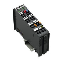
WAGO Inc. Encoder 24 VDC Diff 32Bit XTR Manual (54 pages)
Incremental Encoder Interface; 24 VDC; Differential Input; 32 Bits; Extreme For WAGO-I/O-SYSTEM 750 XTR
Brand:
WAGO
| Category:
Recording Equipment
| Size: 2.73 MB
Table of Contents
Table of Contents
3
1 Notes about this Documentation
5
Validity of this Documentation
5
Copyright
5
Symbols
6
Number Notation
7
Font Conventions
7
Table 1: Number Notation
7
Table 2: Font Conventions
7
2 Important Notes
8
Legal Bases
8
Subject to Changes
8
Personnel Qualifications
8
Use of the 750 Series in Compliance with Underlying Provisions
8
Technical Condition of Specified Devices
9
Disposal
9
2.1.4.1.1 Electrical and Electronic Equipment
9
2.1.4.1.2 Packaging
10
Safety Advice (Precautions)
11
3 Device Description
14
Table 3: Inputs/Outputs
14
View
16
Figure 1: View
16
Table 4: Legend for Figure "View
16
Connectors
17
Data Contacts/Local Bus
17
Power Jumper Contacts/Field Supply
17
Figure 2: Data Contacts
17
CAGE CLAMP ® Connectors
18
Figure 3: CAGE CLAMP ® Connectors
18
Table 5: Legend for Figure "CAGE CLAMP ® Connectors
18
Display Elements
19
Figure 4: Display Elements
19
Table 6: Legend for Figure "Display Elements
19
Operating Elements
20
Schematic Diagram
20
Figure 5: Schematic Diagram
20
Technical Data
21
Device Data
21
Supply
21
Table 7: Technical Data - Device
21
Table 8: Technical Data - Supply
21
In-/Outputs
22
Digital Outputs (N1, N2)
22
Digital Inputs (Latch, Gate, Ref)
22
Quadrature Inputs (A, /A, B, /B, C, /C)
22
Table 9: Technical Data - In-/Outputs
22
Table 10: Technical Data - Digital Outputs (N1, N2)
22
Table 11: Technical Data - Digital Inputs (Latch, Gate, Ref)
22
Table 12: Technical Data - Quadrature Inputs (A, /A, B, /B, C, /C)
22
Quadrature Decoder
23
Connection Technology
23
Mechanical Conditions
23
Climatic Environmental Conditions
23
Table 13: Technical Data - Quadrature Decoder
23
Table 14: Technical Data - Wiring Interface
23
Table 15: Technical Data - Data Contacts
23
Table 16: Technical Data - Mechanical Conditions
23
Table 17: Technical Data - Climatic Environmental Conditions
23
Approvals
24
Standards and Guidelines
25
Table 18: Standards and Rated Conditions for Explosion Protection Applications
25
Table 19: Climatic and Mechanical Environmental Conditions and
26
Table 20: EMC - Immunity to Interference
27
Table 21: EMC - Emission of Interference
29
Table 22: Standards and Rated Conditions for Rail Applications (en 50155)
30
4 Process Image
31
Table 23: Process Image
31
Table 24: Mappzd
31
Table 26: Status Byte S1
31
Table 27: Control Byte C0
31
Table 28: Control Byte C1
31
Control/Status Byte
32
Table 25: Status Byte S0
32
5 Function Description
36
Table 29: Function Description - Inputs
36
6 Mounting
37
Mounting Sequence
37
Inserting and Removing Devices
38
Inserting the I/O Module
38
Figure 6: Insert I/O Module (Example)
38
Removing the I/O Module
39
Figure 7: Snap the I/O Module into Place (Example)
39
Figure 8: Removing the I/O Module (Example)
39
7 Connect Devices
40
Connecting a Conductor to the CAGE CLAMP
40
Figure 9: Connecting a Conductor to a CAGE CLAMP
40
8 Use in Hazardous Environments
41
Marking Configuration Examples
42
Marking for Europe According to ATEX and Iecex
42
Figure 10: Marking Example According to ATEX and Iecex
42
Figure 11: Text Detail - Marking Example According to ATEX and Iecex
42
Table 30: Description of Marking Example According to ATEX and Iecex
43
Figure 12: Marking Example for Approved Ex I I/O Module According to ATEX
44
Figure 13: Text Detail - Marking Example for Approved Ex I I/O Module
44
Table 31: Description of Marking Example for Approved Ex I I/O Module According to ATEX and Iecex
45
Table 33: Description of Marking Example for Approved Ex I I/O Module
45
Marking for the United States of America (NEC) and Canada (CEC)
46
Figure 14: Marking Example According to NEC
46
Figure 15: Text Detail - Marking Example According to NEC 500
46
Table 32: Description of Marking Example According to NEC 500
46
Figure 16: Text Detail - Marking Example for Approved Ex I I/O Module
47
Figure 17: Text Detail - Marking Example for Approved Ex I I/O Module
47
Table 34: Description of Marking Example for Approved Ex I I/O Modules
47
Figure 18: Text Detail - Marking Example for Approved Ex I I/O Modules
48
Table 35: Description of Marking Example for Approved Ex I I/O Modules
48
Installation Regulations
49
Special Notes Regarding Explosion Protection
49
Special Notes Regarding ANSI/ISA Ex
51
List of Figures
52
List of Tables
53
Advertisement
Advertisement
Related Products
WAGO 750-468
WAGO 750-468/000-001
WAGO 750-468/000-200
WAGO 750-468/025-000
WAGO 750-630
WAGO 750-630/040-001
WAGO 750-637/000-003
WAGO 750-637/040-001
WAGO 750-652
WAGO 767-5204
WAGO Categories
I/O Systems
Control Unit
Power Supply
Switch
Controller
More WAGO Manuals
Login
Sign In
OR
Sign in with Facebook
Sign in with Google
Upload manual
Upload from disk
Upload from URL