Sign In
Upload
Manuals
Brands
WAGO Manuals
GPS
753-649
WAGO 753-649 Manuals
Manuals and User Guides for WAGO 753-649. We have
1
WAGO 753-649 manual available for free PDF download: Manual
WAGO 753-649 Manual (50 pages)
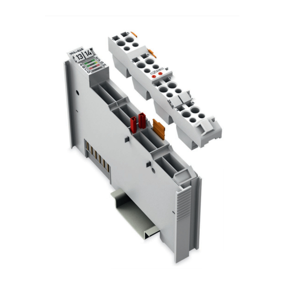
M-Bus Master Module for the Connection of M-Bus Devices For WAGO-I/O-SYSTEM 750
Brand:
WAGO
| Category:
GPS
| Size: 3 MB
Table of Contents
Table of Contents
3
1 Notes about this Documentation
5
Validity of this Documentation
5
Copyright
5
Symbols
6
Number Notation
8
Font Conventions
8
Table 1: Number Notation
8
Table 2: Font Conventions
8
2 Important Notes
9
Legal Bases
9
Subject to Changes
9
Personnel Qualifications
9
Use of the 750 Series in Compliance with Underlying Provisions
9
Technical Condition of Specified Devices
10
Safety Advice (Precautions)
11
3 Device Description
14
Table 3: Compatibility List 753-649
15
View
16
Figure 1: View of Device
16
Table 4: Legend for Figure "View
16
Connectors
17
Data Contacts/Local Bus
17
Figure 2: Data Contacts
17
Power Jumper Contacts/Field Supply
18
Figure 3: Power Jumper Contacts
18
Table 5: Legend for Figure "Power Jumper Contacts
18
CAGE CLAMP ® Connectors
19
Figure 4: CAGE CLAMP ® Connections
19
Table 6: Legend for Figure "CAGE CLAMP ® Connections
19
Display Elements
20
Figure 5: Display Elements
20
Table 7: Legend for the Figure "Display Elements
20
Operating Elements
21
Schematic Diagram
21
Figure 6: Schematic Circuit Diagram
21
Overcurrent Shutdown
22
Technical Data
23
Device Data
23
Power Supply
23
Table 8: Technical Data - Device
23
Table 9: Technical Data - Power Supply
23
Communication
24
Connection Type
24
Table 10: Technical Data - Communication
24
Table 11: Technical Data - Wiring Level
24
Table 12: Technical Data - Power Jumper Contacts
24
Table 13: Technical Data - Data Contacts
24
Climatic Environmental Conditions
25
Table 14: Technical Data - Climatic Environmental Conditions
25
Approvals
26
Standards and Guidelines
27
4 Process Image
28
5 Mounting
28
Mounting Sequence
28
Inserting and Removing Devices
29
Inserting the I/O Module
29
Figure 7: Insert I/O Module (Example)
29
Figure 8: Snap the I/O Module into Place (Example)
29
Removing the I/O Module
30
I/O Modules with Pluggable Wiring Level (Series 753)
30
Figure 9: Removing the I/O Module (Example)
30
Figure 10: Plug and I/O Module
30
Coding
31
Figure 11: Assignment of I/O Module to Plug Using Mini-WSB Tags
31
Figure 12: Attachment of Cable Binders
31
Figure 13: Assembling the Coding Fingers
31
Figure 14: Inserting the Coding Fingers
32
Figure 15: Plugging the Plug into Place
32
Figure 16: "Sure Match" Coding Fingers
32
Plug Removal
33
Figure 17: Pulling the Pull Tab
33
Figure 18: Removing the Plug Without Tools
33
Figure 19: Removing the Plug Using a Screwdriver
33
6 Connect Devices
34
Connecting a Conductor to the CAGE CLAMP
34
Figure 20: Connecting a Conductor to a CAGE CLAMP
34
Connection Example
35
Figure 21: Connection Example
35
Important Installation Notes
36
Field Supply
36
M-Bus Cable
37
M-Bus Network
37
7 Commissioning
38
Preparation
38
Table 15: Example of a Fieldbus Node Setup
38
Configuration and Data Access
39
Configuration and Access Via WAGO-I/O-PRO
39
Configuration and Access Via Mbsheet and MBCONF
40
Install Components
41
Figure 22: Windows Security Alert about the Eltima Software
41
Figure 23: Windows Prompt about Installation of the Mbsheet Software
42
Open Mbsheet
43
Figure24: Opening Mbsheet Via WAGO-I/O-CHECK
43
Figure 25: Graphical User Interface of Mbsheet
44
Open MBCONF
45
Use Mbsheet and MBCONF
45
Exit Mbsheet and MBCONF
46
Configuration and Access Via E!Cockpit
46
List of Figures
47
List of Tables
48
Advertisement
Advertisement
Related Products
WAGO 753-647
WAGO WAGO-I/O-SYSTEM 753-661/000-003
WAGO 753-668/000-004
WAGO 753-646
WAGO 753-661/000-004
WAGO 753-452
WAGO 753-1630
WAGO 753-513
WAGO 753-1631
WAGO 753-466
WAGO Categories
I/O Systems
Control Unit
Power Supply
Switch
Controller
More WAGO Manuals
Login
Sign In
OR
Sign in with Facebook
Sign in with Google
Upload manual
Upload from disk
Upload from URL