
Summary of Contents for WAGO 753-649
- Page 1 Manual WAGO-I/O-SYSTEM 750 753-649 M-Bus Master Module for the Connection of M-Bus Devices Version 1.1.2...
- Page 2 We wish to point out that the software and hardware terms as well as the trademarks of companies used and/or mentioned in the present manual are generally protected by trademark or patent. WAGO is a registered trademark of WAGO Verwaltungsgesellschaft mbH. Manual Version 1.1.2...
-
Page 3: Table Of Contents
WAGO-I/O-SYSTEM 750 Table of Contents 753-649 M-Bus Master Module Table of Contents Notes about this Documentation .............. 5 Validity of this Documentation ..............5 Copyright....................5 Symbols ....................6 Number Notation ..................8 Font Conventions ..................8 Important Notes ..................9 Legal Bases ..................... - Page 4 M-Bus Network .................. 37 Commissioning ..................38 Preparation .................... 38 Configuration and Data Access ............. 39 7.2.1 Configuration and Access via WAGO-I/O-PRO ........ 39 7.2.2 Configuration and Access via MBSheet and MBCONF ....40 7.2.2.1 Install Components ............... 41 7.2.2.2 Open MBSheet ................
-
Page 5: Notes About This Documentation
This documentation is only applicable to the I/O module 753-649 (M-Bus Master Module). The I/O module 753-649 shall only be installed and operated according to the instructions in this manual and in the manual for the used fieldbus coupler or controller. -
Page 6: Symbols
Notes about this Documentation WAGO-I/O-SYSTEM 750 753-649 M-Bus Master Module Symbols Personal Injury! Indicates a high-risk, imminently hazardous situation which, if not avoided, will result in death or serious injury. Personal Injury Caused by Electric Current! Indicates a high-risk, imminently hazardous situation which, if not avoided, will result in death or serious injury. - Page 7 WAGO-I/O-SYSTEM 750 Notes about this Documentation 753-649 M-Bus Master Module Additional Information: Refers to additional information which is not an integral part of this documentation (e.g., the Internet). Manual Version 1.1.2...
-
Page 8: Number Notation
Notes about this Documentation WAGO-I/O-SYSTEM 750 753-649 M-Bus Master Module Number Notation Table 1: Number Notation Number Code Example Note Decimal Normal notation Hexadecimal 0x64 C notation Binary '100' In quotation marks, nibble separated '0110.0100' with dots (.) Font Conventions... -
Page 9: Important Notes
2.1.1 Subject to Changes WAGO Kontakttechnik GmbH & Co. KG reserves the right to provide for any alterations or modifications. WAGO Kontakttechnik GmbH & Co. KG owns all rights arising from the granting of patents or from the legal protection of utility patents. -
Page 10: Technical Condition Of Specified Devices
These modules contain no parts that can be serviced or repaired by the user. The following actions will result in the exclusion of liability on the part of WAGO Kontakttechnik GmbH & Co. KG: •... -
Page 11: Safety Advice (Precautions)
WAGO-I/O-SYSTEM 750 Important Notes 753-649 M-Bus Master Module Safety Advice (Precautions) For installing and operating purposes of the relevant device to your system the following safety precautions shall be observed: Do not work on devices while energized! All power sources to the device shall be switched off prior to performing any installation, repair or maintenance work. - Page 12 Important Notes WAGO-I/O-SYSTEM 750 753-649 M-Bus Master Module Use SELV power source only! The fieldbus coupler/controller must only be powered from a SELV (Safety Extra Low Voltage) power source. Replace defective or damaged devices! Replace defective or damaged device/module (e.g., in the event of deformed contacts).
- Page 13 WAGO-I/O-SYSTEM 750 Important Notes 753-649 M-Bus Master Module Avoid electrostatic discharge! The devices are equipped with electronic components that may be destroyed by electrostatic discharge when touched. Please observe the safety precautions against electrostatic discharge per DIN EN 61340-5-1/-3. When handling the devices, please ensure that environmental factors (personnel, work space and packaging) are properly grounded.
-
Page 14: Device Description
WAGO-I/O-SYSTEM 750 753-649 M-Bus Master Module Device Description The M-Bus master 753-649 acts as a master in M-Bus communication systems, allowing M-Bus slaves to be directly connected to the WAGO-I/O-SYSTEM 750 with a two-wire interface per EN 13757. The M-Bus master communicates with the M-Bus slaves via the M-Bus protocol and forms the interface between the M-Bus network and the processing software. -
Page 15: Table 3: Compatibility List 753-649
WAGO-I/O-SYSTEM 750 Device Description 753-649 M-Bus Master Module The I/O module 753-649 can be operated on the following fieldbus controllers of the WAGO-I/O-SYSTEM 750 from the specified firmware revision level: Table 3: Compatibility List 753-649 Fieldbus Firmware Revision Bus System... -
Page 16: View
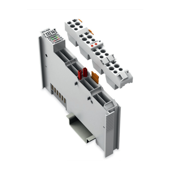
Device Description WAGO-I/O-SYSTEM 750 753-649 M-Bus Master Module View Figure 1: View of Device Table 4: Legend for Figure “View” Pos. Description Details See Section Marking possibility with Mini- Status-LEDs “Device Description” > “Display Elements” Data contacts “Device Description” > “Connectors”... -
Page 17: Connectors
WAGO-I/O-SYSTEM 750 Device Description 753-649 M-Bus Master Module Connectors 3.2.1 Data Contacts/Local Bus Communication between the fieldbus coupler/controller and the I/O modules as well as the system supply of the I/O modules is carried out via the local bus. The contacting for the local bus consists of 6 data contacts, which are available as self-cleaning gold spring contacts. -
Page 18: Power Jumper Contacts/Field Supply
The blade contacts are sharp-edged. Handle the I/O module carefully to prevent injury. Do not touch the blade contacts. The I/O module 753-649 has 2 self-cleaning power jumper contacts that supply and transmit power for the field side. The contacts on the left side of the I/O module are designed as blade contacts and those on the right side as spring contacts. -
Page 19: Cage Clamp ® Connectors
WAGO-I/O-SYSTEM 750 Device Description 753-649 M-Bus Master Module ® 3.2.3 CAGE CLAMP Connectors ® Figure 4: CAGE CLAMP Connections ® Table 6: Legend for Figure “CAGE CLAMP Connections” Connection Function Connection for M-Bus cable (positive), +M-Bus M-Bus power supply Connection for M-Bus cable (negative), −M-Bus... -
Page 20: Display Elements
Device Description WAGO-I/O-SYSTEM 750 753-649 M-Bus Master Module Display Elements Figure 5: Display Elements Table 7: Legend for the Figure “Display Elements” LED Designation State Function Not ready for operation, or no/faulty local Local bus bus communication communication Ready for operation and uninterrupted... -
Page 21: Operating Elements
WAGO-I/O-SYSTEM 750 Device Description 753-649 M-Bus Master Module Operating Elements The I/O module 753-649 does not have any electro-mechanical operating elements. Changes to the configuration and parameters are made via the higher-order control. Schematic Diagram Figure 6: Schematic Circuit Diagram Manual Version 1.1.2... -
Page 22: Overcurrent Shutdown
Device Description WAGO-I/O-SYSTEM 750 753-649 M-Bus Master Module Overcurrent Shutdown Active current monitoring ensures short circuit resistance of the M-Bus master interface. If the M-Bus current exceeds the threshold (see section “Technical Data” > … > “Communication”), the M-Bus master shuts down the M-Bus power to the CAGE ®... -
Page 23: Technical Data
WAGO-I/O-SYSTEM 750 Device Description 753-649 M-Bus Master Module Technical Data 3.7.1 Device Data Table 8: Technical Data – Device Width 12 mm Height (from upper edge of DIN-rail) 64 mm Depth 100 mm Weight 54 g 3.7.2 Power Supply Table 9: Technical Data – Power Supply... -
Page 24: Communication
Device Description WAGO-I/O-SYSTEM 750 753-649 M-Bus Master Module 3.7.3 Communication Table 10: Technical Data – Communication Transmission channels 1, bidirectional Internal data width 24 bytes (Mailbox 2.0 with 22-byte length) Startup and configuration WAGO-I/O-PRO V. 2.3, e!COCKPIT Baud rates •... -
Page 25: Climatic Environmental Conditions
WAGO-I/O-SYSTEM 750 Device Description 753-649 M-Bus Master Module 3.7.5 Climatic Environmental Conditions Table 14: Technical Data ‒ Climatic Environmental Conditions Surrounding air temperature, operation 0 °C … 50 °C Altitude above sea level 2000 m Surrounding air temperature, storage −20 °C … +85 °C... -
Page 26: Approvals
Approvals More information about approvals. Detailed references to the approvals are listed in the document “Overview Approvals WAGO-I/O-SYSTEM 750”, which you can find via the internet under: www.wago.com DOWNLOADS Documentation System Description. The following approvals have been granted to 753-649 I/O modules:... -
Page 27: Standards And Guidelines
WAGO-I/O-SYSTEM 750 Device Description 753-649 M-Bus Master Module Standards and Guidelines 753-649 I/O modules meet the following requirements on emission and immunity of interference: EMC CE-Immunity to interference EN 61000-6-2 EMC CE-Emission of interference EN 61000-6-3 Note Use recommended power supplies for reliable CE immunity to... -
Page 28: Process Image
753-649 M-Bus Master Module Process Image The M-Bus master 753-649 has a cyclic 24 byte process image for the local bus. An acyclic channel that occupies 22 bytes of data is embedded in the process image for the process communication. The input and output data exchange is event-driven. -
Page 29: Inserting And Removing Devices
WAGO-I/O-SYSTEM 750 Mounting 753-649 M-Bus Master Module Inserting and Removing Devices Do not work when devices are energized! High voltage can cause electric shock or burns. Switch off all power to the device prior to performing any installation, repair or maintenance work. -
Page 30: Removing The I/O Module
Mounting WAGO-I/O-SYSTEM 750 753-649 M-Bus Master Module 5.2.2 Removing the I/O Module Note Remove pluggable wiring! Before removing a 753 Series I/O Module from the node, you must first remove the plug (pluggable wiring) from the I/O module (see section “Plug Removal”)! -
Page 31: Coding
WAGO-I/O-SYSTEM 750 Mounting 753-649 M-Bus Master Module Figure 11: Assignment of I/O Module to Plug Using Mini-WSB Tags This plug provides an option for attaching cable binders. Figure 12: Attachment of Cable Binders 5.3.1 Coding Coding using small plastic pins and sockets facilitates mating of the I/O module with the appropriate plug. -
Page 32: Figure 14: Inserting The Coding Fingers
Mounting WAGO-I/O-SYSTEM 750 753-649 M-Bus Master Module Figure 14: Inserting the Coding Fingers Place the plug onto the I/O module. Figure 15: Plugging the Plug into Place When the plug is removed the sockets remain in the I/O module. The coded plug can only fit in the corresponding coded I/O module (see figures below). -
Page 33: Plug Removal
WAGO-I/O-SYSTEM 750 Mounting 753-649 M-Bus Master Module 5.3.2 Plug Removal Remove the plug from the I/O module by pulling the orange pull tab on the plug toward the top of the I/O module. Figure 17: Pulling the Pull Tab The plug detaches from the I/O module. -
Page 34: Connect Devices
Only one conductor may be connected to each CAGE CLAMP Do not connect more than one conductor at one single connection! If more than one conductor must be routed to one connection, these must be connected in an up-circuit wiring assembly, for example using WAGO feed- through terminals. ®... -
Page 35: Connection Example
WAGO-I/O-SYSTEM 750 Connect Devices 753-649 M-Bus Master Module Connection Example Figure 21: Connection Example Manual Version 1.1.2... -
Page 36: Important Installation Notes
Connect Devices WAGO-I/O-SYSTEM 750 753-649 M-Bus Master Module Important Installation Notes Do not work when devices are energized! High voltage can cause electric shock or burns. Switch off all power to the device prior to performing any installation, repair or maintenance work. -
Page 37: M-Bus Cable
WAGO-I/O-SYSTEM 750 Connect Devices 753-649 M-Bus Master Module 6.3.2 M-Bus Cable If shielded cables are used, the cable shielding should be placed on the FE connection of the M-Bus master. The cabling of an M-Bus segment must meet the general requirements of standard EN 13757-2. -
Page 38: Commissioning
753-649 M-Bus Master Module Commissioning Preparation The 753-649 I/O module in the fieldbus node is powered via the power jumper contact. Use of an appropriate WAGO power supply is recommended for this purpose (see section “Technical Data” > “Power Supply”). -
Page 39: Configuration And Data Access
7.2.1 Configuration and Access via WAGO-I/O-PRO For initial startup of the M-Bus master and configuration of the M-Bus network connected to it, you need the WAGO-I/O-PRO development environment (Item No.: 759-333). Download the M-Bus library free of charge To create and use your own IEC application (CODESYS 2.3) you can download the “MBUS_649_01.lib”... -
Page 40: Configuration And Access Via Mbsheet And Mbconf
WAGO eShop at: www.wago.com If you need an update for an earlier version of WAGO-I/O-CHECK, you can get it from WAGO customer support. M-Bus Connector is software that provides a virtual COM port through which MBSheet is connected to WAGO-I/O-CHECK. -
Page 41: Install Components
WAGO-I/O-SYSTEM 750 Commissioning 753-649 M-Bus Master Module 7.2.2.1 Install Components Install the software applications in the following order: WAGO-I/O-CHECK Version 3.15 or higher is necessary. MBCONF Installation is optional. M-Bus Connector with MBSheet The first time you install M-Bus Connector, you receive a Windows security alert about the ELTIMA software during the installation process (see following figure). -
Page 42: Figure 23: Windows Prompt About Installation Of The Mbsheet Software
Commissioning WAGO-I/O-SYSTEM 750 753-649 M-Bus Master Module Figure 23: Windows Prompt about Installation of the MBSheet Software Once all applications are installed, you can use MBSheet and MBCONF. Manual Version 1.1.2... -
Page 43: Open Mbsheet
Open MBSheet Proceed as follows in order to access MBSheet: Open WAGO-I/O-CHECK. If the Monitor or Control mode is activated in WAGO-I/O-CHECK, deactivate it. Click the corresponding button in the toolbar, so that it is no longer highlighted. This step is unnecessary if configuring for the first time. -
Page 44: Figure 25: Graphical User Interface Of Mbsheet
Commissioning WAGO-I/O-SYSTEM 750 753-649 M-Bus Master Module The MBSheet user interface then opens: Figure 25: Graphical User Interface of MBSheet While MBSheet is open, the WAGO-I/O-CHECK user interface is locked. Manual Version 1.1.2... -
Page 45: Open Mbconf
WAGO-I/O-SYSTEM 750 Commissioning 753-649 M-Bus Master Module 7.2.2.3 Open MBCONF For using MBCONF, M-Bus Connector and MBSheet are required to be installed. Proceed as follows in order to access MBCONF: Open MBSheet (see section “Start-Up” > … > “Open MBSheet”). -
Page 46: Exit Mbsheet And Mbconf
Download e!COCKPIT manual You can find information on using the e!COCKPIT development environment (Item No.: 2759-101/-1101) in the “ e!COCKPIT ” software manual, which you can download free of charge from the WAGO website at: www.wago.com Manual Version 1.1.2... -
Page 47: List Of Figures
Figure 21: Connection Example ................35 Figure 22: Windows Security Alert about the Eltima Software......41 Figure 23: Windows Prompt about Installation of the MBSheet Software ... 42 Figure24: Opening MBSheet via WAGO-I/O-CHECK ......... 43 Figure 25: Graphical User Interface of MBSheet ..........44 Manual... -
Page 48: List Of Tables
List of Tables Table 1: Number Notation ..................8 Table 2: Font Conventions ..................8 Table 3: Compatibility List 753-649 ..............15 Table 4: Legend for Figure “View” ............... 16 Table 5: Legend for Figure “Power Jumper Contacts” ......... 18 ®... - Page 49 WAGO-I/O-SYSTEM 750 List of Tables 753-649 M-Bus Master Module Manual Version 1.1.2...
- Page 50 WAGO Kontakttechnik GmbH & Co. KG Postfach 2880 • D - 32385 Minden Hansastraße 27 • D - 32423 Minden Phone: +49 571 887 – 0 Fax: +49 571 887 – 844169 E-Mail: info@wago.com Internet: www.wago.com...
Need help?
Do you have a question about the 753-649 and is the answer not in the manual?
Questions and answers