Sign In
Upload
Manuals
Brands
Vertiv Manuals
UPS
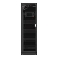
APM Plus 0500kMK16FN02000
Vertiv APM Plus 0500kMK16FN02000 Manuals
Manuals and User Guides for Vertiv APM Plus 0500kMK16FN02000. We have
2
Vertiv APM Plus 0500kMK16FN02000 manuals available for free PDF download: User Manual
Vertiv APM Plus 0500kMK16FN02000 User Manual (200 pages)
50-500 kVA UPS
Brand:
Vertiv
| Category:
UPS
| Size: 5 MB
Table of Contents
Table of Contents
3
1 Important Safety Instructions
9
2 Overview
15
Features
15
Design Concept
15
System Design
15
Bypass
19
System Control Principle
19
UPS Power Supply Switch Configuration
21
Battery Circuit Breaker (BCB)
23
Parallel System
24
Parallel System Features
24
Parallel System Requirements
24
Operation Modes
24
Battery Management
31
Normal Function
31
Advanced Function
32
Battery Temperature Compensation
33
Battery Protection
33
3 Mechanical Installation
35
Precautions
35
Transportation
36
Tools
36
Unpacking
38
Initial Inspection
40
Environmental Requirement
40
UPS Location Selection
40
Battery Location Selection
40
Storage
41
Mechanical Requirement
41
Composition
41
Moving Cabinet
41
Clearance
41
Cable Access Mode
41
Installation Drawings
42
4 Electrical Installation
45
Wiring of Power Cable
45
System Configuration
45
Maximum Steady State AC and DC Currents
45
Recommended CSA of UPS Cable
46
Selection of UPS I/O Switch and Battery Switch
47
Distance between the UPS Connection Point and Floor
48
Notes
48
Power Cable Connecting Terminal
48
Protection Ground
48
External Protective Device
49
Power Cable Connection Steps
51
Wiring of Signal Cable
57
Overview
57
Dry Contact Port J6
58
Dry Contact Port J7
59
Dry Contact Port J8
62
REPO Port
63
Host Communication Port
63
Parallel and LBS Communication Ports
63
Intellislot Port
64
Signal Cable Connection Steps
64
5 Operator Control and Display Panel
67
Introduction
67
Navigating through the Liebert APM Plus Touchscreen Control Panel
68
Access Level Log-In
68
Liebert APM Plus Touchscreen Control Panel Components
69
Operation
75
Log in to the Liebert APM Plus Touchscreen Control Panel
75
Customizing the Display
75
Operator Controls
83
Viewing UPS Status
90
Viewing UPS Data with the Status Gauge
90
Viewing UPS Data with the Status Panel
94
Logs-Alarms and Events
99
Viewing UPS Component Status
101
Status Bar Component
104
Status Bar Messages
104
Alarm List
108
6 Single UPS Operation Introduction
113
Brief Introduction
113
Precautions
113
Power Switch
114
UPS Startup Procedures
117
Startup Procedures in Normal Mode
117
Startup Procedures in ECO Mode
122
Startup Procedures in Battery Mode (Battery Cold Start)
123
Procedures for Transfer between Operation Modes
124
Transfer from Normal Mode to Battery Mode
124
Transfer from Normal Mode to Bypass Mode
124
Transfer from Bypass Mode to Normal Mode
124
Transfer from Normal Mode to Maintenance Mode
125
Transfer from Maintenance Mode to Normal Mode
126
Battery Test Procedures
127
UPS Shutdown Procedures
129
Procedures for Completely Powering down UPS
129
Procedures for Completely Powering down UPS While Maintaining Power to Load
129
EPO Procedures
130
UPS Reset Procedures after EPO
130
Automatic Restart
130
Selecting Language
131
Changing Current Date and Time
132
Control Password
133
7 Battery
135
Introduction
135
Safety
135
UPS Battery
137
Precautions for Installation Design
137
Battery Installation Environment and Number of Batteries
138
Installation Environment
138
Number of Batteries
139
Battery Protection
139
Battery Installation and Connection
139
Battery Installation
140
Battery Connection
140
Design of Battery Room
142
Common Battery String
143
BCB Cabinet (Option 1)-Applicable for APAC Region
144
BCB Cabinet (Option 2)-Applicable for APAC Region
149
Battery Temperature Sensor (Optional)
153
Battery Ground Fault Detector (Optional)- Applicable for APAC Region
154
BCB Reference Current and Connection
155
Battery Maintenance
156
Disposal of Used Battery
156
8 Parallel System and LBS System
157
General
157
System Installation Procedures
157
Preliminary Checks
157
Cabinet Installation
157
External Protective Device
159
Power Cable
159
Parallel Cable
160
Remote EPO
161
Operation Procedures for Parallel System
162
Startup Procedures in Normal Mode
162
Maintenance Bypass Procedures
163
Procedures for Isolating One UPS Module from Parallel System
164
Procedures for Inserting One Isolated UPS Module in Parallel System
164
Procedures for Completely Powering down UPS
164
LBS System
165
Cabinet Installation
165
External Protective Device
167
Power Cable
167
LBS Cable
168
9 Options
171
Option List
171
Option Introduction
172
Battery Temperature Sensor Kit
172
Battery Ground Fault Kit- Applicable for APAC Region
172
Seismic Anchor Kit
173
SIC Card- Applicable for APAC Region
176
UF-RS485 Card- Applicable for APAC Region
177
IS-Relay Card
179
BCB Cabinet- Applicable for APAC Region
180
Parallel Cable
180
LBS Cable
180
Shorting Copper Bar Kit
180
10 Communication
181
SNMP Protocol Communication
181
Modbus Protocol Communication
181
Dry Contact Communication
182
Communication through IS-Relay Card
182
Communication through Dry Contact Port of Central Control Module
182
11 Service and Maintenance
183
Safety
183
Service Procedures of Power Module and Bypass Power Module
183
Notes
183
Service Procedures of Power Module
184
Replacement Procedures of Bypass Power Module
184
Key Components and Service Life of UPS
185
Life Parameters and the Proposed Replacement Time of Key Components
185
Replacement of Air Filter
186
Maintenance of UPS and Options
187
12 Specifications
189
Conformance and Standards
189
Environmental Characteristics
189
Mechanical Characteristics
190
Electrical Characteristics (Input Rectifier)
190
Electrical Characteristics (Intermediate DC Circuit)
191
Electrical Characteristics (Inverter Output)
192
Electrical Characteristics (Bypass Input)
193
Efficiency and Loss
193
Appendices
195
Appendix A: Glossary
195
Appendix B: Hazardous Substances and Content
196
Appendix C: Disposal after End of Product (Applicable for India)
197
Advertisement
Vertiv APM Plus 0500kMK16FN02000 User Manual (188 pages)
Brand:
Vertiv
| Category:
UPS
| Size: 32 MB
Table of Contents
Table of Contents
3
Important Safety Instructions I
9
Verview
17
Features
17
Design Concept
17
System Design
17
Bypass
21
System Control Principle
21
UPS Power Supply Switch Configuration
23
Battery Circuit Breaker (BCB)
25
Parallel System
26
Parallel System Features
26
Parallel System Requirements
26
Operation Modes
26
Battery Management
31
Normal Function
31
Advanced Function
32
Battery Temperature Compensation
33
Battery Protection
33
Echanical Installation
35
Precautions
35
Transportation
35
Tools
36
Unpacking
38
Initial Inspection
40
Environmental Requirement
40
UPS Location Selection
40
Battery Location Selection
41
Storage
41
Mechanical Requirement
42
Composition
42
Moving Cabinet
42
Clearance
42
Cable Access Mode
42
Installation Drawings
43
Electrical Installation
47
Wiring of Power Cable
47
System Configuration
47
Maximum Steady State AC and DC Currents
47
Recommended CSA of UPS Cable
48
Selection of UPS I/O Switch and Battery Switch
48
Distance between the UPS Connection Point and Floor
48
Notes
49
Power Cable Connecting Terminal
49
Protection Ground
49
External Protective Device
49
Power Cable Connection Steps
51
Wiring of Signal Cable
56
Overview
56
Dry Contact Port J6
57
Dry Contact Port J7
58
Dry Contact Port J8
61
REPO Port
62
Host Communication Port
62
Parallel and LBS Communication Ports
62
Intellislot Port
63
Signal Cable Connection Steps
63
Ouch Screen
65
Introduction
65
Navigating through the Liebert APM Plus Touchscreen Control Panel
67
Access Level Log-In
67
Liebert APM Plus Touchscreen Control Panel Components
68
Operation
74
Log in to the Liebert APM Plus Touchscreen Control Panel
74
Customizing the Display
75
Operator Controls
82
Viewing UPS Status
88
Viewing UPS Data with the Status Gauge
89
Viewing UPS Data with the Status Panel
93
Logs-Alarms and Events
99
Viewing UPS Component Status
101
Status Bar Component
104
Status Bar Messages
104
Alarm List
108
Single UPS Operation Introduction
113
Brief Introduction
113
Precautions
113
Power Switch
114
UPS Startup Procedures
117
Startup Procedures in Normal Mode
117
Startup Procedures in ECO Mode
120
Startup Procedures in Battery Mode (Battery Cold Start)
121
Procedures for Transfer between Operation Modes
122
Transfer from Normal Mode to Battery Mode
122
Transfer from Normal Mode to Bypass Mode
122
Transfer from Bypass Mode to Normal Mode
123
Transfer from Normal Mode to Maintenance Mode
123
Transfer from Maintenance Mode to Normal Mode
124
Battery Test Procedures
125
UPS Shutdown Procedures
127
Procedures for Completely Powering down UPS
127
EPO Procedures
127
UPS Reset Procedures after EPO
128
Automatic Restart
128
Selecting Language
129
Changing Current Date and Time
130
Control Password
131
Battery
133
Introduction
133
Safety
134
UPS Battery
136
Precautions for Installation Design
136
Battery Installation Environment and Number of Batteries
137
Installation Environment
137
Number of Batteries
138
Battery Protection
138
Battery Installation and Connection
138
Battery Installation
139
Design of Battery Room
139
Common Battery String
140
BCB Cabinet (Optional)
141
Battery Ground Fault Detector (Optional)
146
BCB Reference Current and Connection
147
Battery Maintenance
148
Disposal of Used Battery
148
Parallel System and LBS System
149
General
149
System Installation Procedures
149
Preliminary Checks
149
Cabinet Installation
149
External Protective Device
151
Power Cable
151
Parallel Cable
151
Remote EPO
152
Operation Procedures for Parallel System
153
Startup Procedures in Normal Mode
153
Maintenance Bypass Procedures
154
Procedures for Isolating One UPS Module from Parallel System
155
Procedures for Inserting One Isolated UPS Module in Parallel System
156
Procedures for Completely Powering down UPS
156
LBS System
157
Cabinet Installation
157
External Protective Device
159
Power Cable
159
LBS Cable
159
P Tions
161
Option List
161
Option Introduction
162
Battery Temperature Sensor Kit
162
Battery Ground Fault Kit
163
Seismic Anchor Kit
163
SIC Card
166
IS-Relay Card
167
UF-RS485 Card
169
BCB Cabinet
170
Parallel Cable
170
LBS Cable
170
Shorting Copper Bar Kit
170
Communication
171
SNMP Protocol Communication
171
Modbus Protocol Communication
171
Dry Contact Communication
172
Communication through IS-Relay Card
172
Communication through Dry Contact Port of Central Control Module
172
Service and M Aintenance 16
173
Safety
173
Service Procedures of Power Module and Bypass Power Module
173
Notes
173
Service Procedures of Power Module
174
Replacement Procedures of Bypass Power Module
174
Key Components and Service Life of UPS
175
Life Parameters and the Proposed Replacement Time of Key Components
175
Replacement of Air Filter
176
Maintenance of UPS and Options
177
Specifications
179
Conformance and Standards
179
Environmental Characteristics
179
Mechanical Characteristics
180
Electrical Characteristics (Input Rectifier)
180
Electrical Characteristics (Battery Bus)
181
Electrical Characteristics (Inverter Output)
182
Electrical Characteristics (Bypass Input)
183
Efficiency and Loss
183
Appendices
185
Appendix A: Glossary
185
Appendix B: Hazardous Substances and Content
186
Advertisement
Related Products
Vertiv LIEBERT PSI5 MINI-TOWER PSI5-1500MT120
Vertiv Liebert PSI5-750MT120
Vertiv Liebert PSI5-2200RT120
Vertiv Liebert PST4-660MT120
Vertiv Liebert PSA5-1500MT120
Vertiv Liebert MicroPOD PD5-20AC20
Vertiv PSI5-3000SRT120LI
Vertiv PSA4-1000MT120
Vertiv Liebert PSI5-800RT120N
Vertiv Liebert PSI5-1100MT120
Vertiv Categories
UPS
Power Supply
Switch
Power distribution unit
Air Conditioner
More Vertiv Manuals
Login
Sign In
OR
Sign in with Facebook
Sign in with Google
Upload manual
Upload from disk
Upload from URL