Sign In
Upload
Manuals
Brands
VersaLogic Manuals
Recording Equipment
VL-EPU-3311
VersaLogic VL-EPU-3311 Manuals
Manuals and User Guides for VersaLogic VL-EPU-3311. We have
2
VersaLogic VL-EPU-3311 manuals available for free PDF download: Hardware Reference Manual, Programmer's Reference Manual
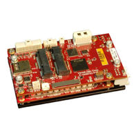
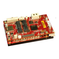
VersaLogic VL-EPU-3311 Hardware Reference Manual (68 pages)
Intel Atom E38xx-based Embedded Processing Unit with SATA, Ethernet, USB, Serial, Video, Mini PCIe Sockets, and microSD
Brand:
VersaLogic
| Category:
Midi processing unit
| Size: 3 MB
Table of Contents
Table of Contents
6
Introduction
10
Figure 1. the Osprey (VL-EPU-3311)
10
Features
11
Technical Specifications
11
Block Diagram
12
Figure 2. Osprey (VL-EPU-3311) Block Diagram
12
Dimensions and Mounting
13
Osprey Dimensions
13
Figure 3. Osprey Dimensions and Mounting Holes
13
VL-HDW-405 Mounting Plate Dimensions
14
Figure 4. Mounting Plate Dimensions
14
Configuration and Setup
15
Initial Configuration
15
Basic Setup
15
Figure 5. Typical Development Configuration
16
BIOS Setup
17
Default BIOS Setup Values
17
Operating System Installation
17
Jumper Blocks
18
Jumper As-Shipped Configuration
18
Jumper Configuration Summary
18
Table 1: Jumper Block V1 - Endpoint Termination
18
Figure 6. Jumpers As-Shipped Configuration
18
Board Features
19
Cpu
19
CPU die Temperature
19
System RAM
19
Flash Storage
19
Table 2: Osprey Memory Characteristics
19
I/O Interfaces
20
Real-Time Clock (RTC)
20
Watchdog Timer
20
External Connectors
21
Baseboard Connector Locations
21
Table 3: Links to Sections Describing Connectors
21
Figure 7. Baseboard Connector Locations
21
Power Delivery
22
Main Power Connector
22
Figure 8. Main Power Connector Pin Orientation
22
Cabling
23
Power Requirements
23
Power Delivery Considerations
23
Table 4: Main Power Connector Pinout
23
Power Button
24
Supported Power States
24
Table 5: Supported Power States
24
Battery Power Options
25
Figure 9. Location and Pin Orientation of the Battery Connector
25
External Speaker
26
Push-Button Reset
26
Figure 10. VL-CBR-0203 Latching Battery Module
26
Leds
27
Figure 11. Location of Status Indicator Leds
27
Figure 12. Location of the Power-Good/Fault Indicator LED
28
Power-Good/Fault Indicator Leds
28
Mass Storage Interfaces
29
SATA Interface
29
Figure 13. Location of the SATA Connector
29
Microsd Socket
30
Emmc Flash
30
Figure 14. Location of the Microsd Socket
30
Multi-Purpose I/O
31
USB Interface
31
Figure 15. Location of the USB Ports
31
Mini Pcie / Msata Sockets
32
Figure 16. Mini Pcie/Msata Sockets
32
Table 6: Mini Pcie / Msata Socket Pinout
33
W_Disable# Signal
34
Figure 17. Mini Pcie Wireless Status Leds
35
Mini Pcie Card Wireless Status Leds
35
Table 7: Mini Pcie Card Wireless Status Leds
35
Figure 18. Location of the Sata/Msata Activity LED
36
Msata Activity LED
36
User I/O Connector
37
Figure 19. Location and Pin Orientation of the User I/O Connector
37
Cabling
38
Table 8: User I/O Connector Pinout and Pin Orientation
38
Serial I/O
39
Serial Ports
39
Figure 20. Location and Pin Orientation of the Serial I/O Connector
39
Cabling
40
COM Port Configuration
40
Serial Port Connector Pinout
40
Console Redirection
40
Table 9: COM1/COM2 Connector Pinout
40
Video Interfaces
41
Mini Displayport++ Connector
41
Figure 21. Location of the Mini Displayport++ Connector
42
Table 10: Mini Displayport++ Connector Pinout
42
Figure 22. VL-CBR-2032 Mini Displayport to VGA Adapter
43
Mini Displayport Cable Options
43
VGA Output
43
LVDS Interface
44
LVDS Flat Panel Display Connector
44
Figure 23. Location of the LVDS Connectors
44
Table 11: LVDS Flat Panel Display Connector Pinout
45
LVDS Backlight Connector
46
Table 12: LVDS Backlight Connector Pinout
46
Network Interfaces
47
Ethernet Connector
47
Figure 24. Location and Pin Orientation of the Ethernet Connector
47
Cabling
48
Table 13: Ethernet Connector Pinout
48
Ethernet Status Leds
49
Figure 25. Onboard Ethernet Status Leds
49
VL-CBR-4005B Paddleboard
50
VL-CBR-4005B Connectors and Indicators
50
Figure 26. VL-CBR-4005B Connectors, Switches, and Leds
50
User I/O Connector
51
Table 14: User I/O Connector Pinout
51
Figure 27. Location and Pin Orientation of the User I/O Connector
51
Cabling
52
On-Board Battery
52
Auxiliary I/O Connector
53
Table 15: Auxiliary I/O Connector Pinout
53
Figure 28. Location and Pin Orientation of Auxiliary I/O Connector
53
Dimensions and Mounting Holes
54
Figure 29. VL-CBR-4005B Dimensions and Mounting Holes
54
Thermal Considerations
55
Selecting the Correct Thermal Solution for Your Application
55
Heat Plate
55
System-Level Considerations
55
CPU Thermal Trip Points
56
Table 16: CPU Thermal Trip Points
56
Table 17: Temperature Monitoring Programs
57
Thermal Specifications, Restrictions, and Conditions
58
Overall Restrictions and Conditions
58
Heat Plate Only Restrictions and Conditions
58
Heat Sink Only Considerations
58
Heat Sink with Fan Considerations
58
Table 18: Absolute Minimum and Maximum Air Temperatures
58
EPU-3311 Thermal Characterization
59
Table 19: EPU-3311 Thermal Testing Setup
59
Figure 30. EPU-3311-EAP Single Core Temperature Relative to Ambient Temperature
60
Test Results
60
Figure 31. EPU-3311-EBP Dual Core Temperature Relative to Ambient Temperature
61
Figure 32. EPU-3311-EDP Quad Core Temperature Relative to Ambient Temperature
62
Figure 33. EPU-3311-EDP Quad Core with Heat Pipe - Temperature Relative to Ambient
63
Table 20: Heat Pipe Additional Configuration Details
63
Installing Versalogic Thermal Solutions
64
Hardware Assembly
64
Figure 34. Hardware Assembly with Heat Plate down
64
Figure 35. Hardware Assembly with Heat Plate up
65
Installing the VL-HDW-406 Passive Heat Sink
66
Figure 36. Installing the Passive Heat Sink
66
Installing the VL-HDW-411 Heat Sink Fan
67
Figure 37. Installing the Heat Sink Fan
67
Installing the VL-HDW-408 Heat Pipe Block
68
Figure 38. Installing the Heat Pipe Block
68
Advertisement
VersaLogic VL-EPU-3311 Programmer's Reference Manual (30 pages)
Brand:
VersaLogic
| Category:
Motherboard
| Size: 0 MB
Table of Contents
Table of Contents
4
Introduction
6
Related Documents
6
System Resources
7
Interrupts
7
FPGA I/O Space
7
Table 1: FPGA I/O Map
7
FPGA Registers
8
Register Access Key
8
Reset Status Key
8
FPGA Register Map
9
Table 2: FPGA Register Map
9
Identifier
10
Address
10
I/O Offset Reset Type
10
Reserved N/A
10
FPGA Register Descriptions
12
Product Information Registers
12
Table 3: PCR - Product Code and LED Register
12
Table 4: PSR - Product Status Register
12
Pled
12
Rev_Level
12
Product_Code
12
Extemp
12
BIOS and Jumper Status Register
13
Timer Registers
13
Table 5: SCR -Status/Control Register
13
Table 6: TICR - 8254 Timer Interrupt Control Register
13
Led_Debug
13
Workver
13
Imask_Tc3
13
Table 7: TISR - 8254 Timer Interrupt Status Register
14
Istat_Tc4
14
Istat_Tc3
14
Table 8: TCR - 8254 Timer Control Register
15
Miscellaneous FPGA Registers
16
Table 9: MISCSR1 - Misc. Control Register #1
16
Aux_Psen
16
Mini1_Psdis
16
Table 10: MISCSR2 - Misc. Control Register #2
17
Usb_Pb1Dis
17
Usb_Obdis
17
Table 11: MISCSR3 - Misc. Control Register #3
18
Table 12: AUXDIR - AUX GPIO Direction Control Register
19
Table 13: AUXPOL - AUX GPIO Polarity Control Register
19
Table 14: AUXOUT - AUX GPIO Output Control Register
19
Dir_Gpio8
19
Dir_Gpio7
19
Pol_Gpio8
19
Pol_Gpio7
19
Out_Gpio8
19
Out_Gpio7
19
Table 15: AUXIN - AUX GPIO Input Status Register
20
Table 16: AUXICR - AUX GPIO Interrupt Mask Register
20
Imask_Gpio8
20
Imask_Gpio7
20
Istat_Gpio8
20
Istat_Gpio7
20
Mode_Gpio8
21
Mode_Gpio7
21
Mode_Gpio6
21
Mode_Gpio5
21
Mode_Gpio4
21
Mode_Gpio3
21
Table 18: AUXMODE1 – AUX I/O Mode Register
21
Wdt_En
22
Wdt_Stat
22
Table 19: WDT_CTL – Watchdog Control Register
22
Com2_Mode
23
Com1_Mode
23
Table 20: WDT_VAL – Watchdog Control Register
23
Table 22: AUXMODE2 - AUX I/O Mode Register #2
24
Table 23: UART1CR – UART1 Control Register (COM1)
25
Table 24: UART2CR – UART2 Control Register (COM2)
26
Uart2_485Adc
27
Uart1_485Adc
27
Uart2_En
27
Uart1_En
27
Table 25: UARTMODE1 – UART MODE Register #1
27
Fast_Mode
28
Table 26: UARTMODE2 – UART MODE Register #2
28
Programming Information for Hardware Interfaces
29
Watchdog Timer
29
Programmable LED
29
Processor WAKE# Capabilities
30
Advertisement
Related Products
VersaLogic VL-EPU-3312
VersaLogic VL-EPU-4012
VersaLogic VL-EPU-3310
VersaLogic Raven VL-EPU-3312-EAP
VersaLogic Raven VL-EPU-3312-EDP
VersaLogic Raven VL-EPU-3312-EBP
VersaLogic VL-EPU-4460
VersaLogic Blackbird VL-EPU4562
VersaLogic Blackbird VL-EPU4462
VersaLogic VL-EPU-4011
VersaLogic Categories
Motherboard
Single board computers
Computer Hardware
Control Unit
PCI Card
More VersaLogic Manuals
Login
Sign In
OR
Sign in with Facebook
Sign in with Google
Upload manual
Upload from disk
Upload from URL