
Related Manuals for VersaLogic VL-EPU-3311

Summary of Contents for VersaLogic VL-EPU-3311
- Page 1 Hardware Reference Manual REV. November 2020 Osprey (VL-EPU-3311) Intel Atom™ E38xx-based ® Embedded Processing Unit with SATA, Ethernet, USB, Serial, Video, Mini PCIe Sockets, and microSD.
- Page 2 Copyright © 2016-2020 VersaLogic Corp. All rights reserved. Notice: Although every effort has been made to ensure this document is error-free, VersaLogic makes no representations or warranties with respect to this product and specifically disclaims any implied warranties of merchantability or fitness for any particular purpose.
- Page 3 Customer Support If you are unable to solve a problem after reading this manual, visiting the product support page, or searching the KnowledgeBase, contact VersaLogic Technical Support at (503) 747-2261. VersaLogic support engineers are also available via e-mail at Support@VersaLogic.com.
- Page 4 CMOS resetting to factory defaults. Ground Requirement CAUTION: All mounting standoffs are signal ground. For example, if metal standoffs are used to mount to an earth-grounded chassis, it is highly recommended to isolate the standoffs from the chassis. VL-EPU-3311 Reference Manual...
- Page 5 In the USB Configuration menu, disabling the xHCI controller without enabling the EHCI controller prevents the use of all USB devices, including the keyboard. Without a keyboard to navigate BIOS Setup utility, the board may need to be returned to VersaLogic for repair. VL-EPU-3311 Reference Manual...
-
Page 6: Table Of Contents
Contents Introduction ......................... 10 Features ..........................11 Technical Specifications ....................11 Block Diagram ........................12 Dimensions and Mounting ....................13 Osprey Dimensions ....................13 VL-HDW-405 Mounting Plate Dimensions ............14 Configuration and Setup ..................... 15 Initial Configuration ......................15 Basic Setup ........................15 BIOS Setup ........................ - Page 7 Thermal Specifications, Restrictions, and Conditions ........58 Overall Restrictions and Conditions: ..............58 Heat Plate Only Restrictions and Conditions: ............. 58 Heat Sink Only Considerations: ................58 Heat Sink with Fan Considerations: ..............58 EPU-3311 Thermal Characterization ................59 VL-EPU-3311 Reference Manual...
- Page 8 Test Results......................60 Installing VersaLogic Thermal Solutions ................. 64 Hardware Assembly ..................... 64 Installing the VL-HDW-406 Passive Heat Sink ..........66 Installing the VL-HDW-411 Heat Sink Fan ............67 Installing the VL-HDW-408 Heat Pipe Block ............. 68 Tables Table 1: Jumper Block V1 – Endpoint Termination ..................18 Table 2: Osprey Memory Characteristics .....................
- Page 9 Figures Figure 1. The Osprey (VL-EPU-3311) ......................10 Figure 2. Osprey (VL-EPU-3311) Block Diagram ..................12 Figure 3. Osprey Dimensions and Mounting Holes ..................13 Figure 4. Mounting Plate Dimensions ......................14 Figure 5. Typical Development Configuration ..................... 16 Figure 6. Jumpers As-Shipped Configuration....................18 Figure 7.
-
Page 10: Introduction
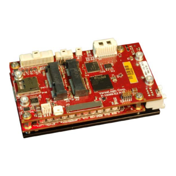
Introduction Figure 1. The Osprey (VL-EPU-3311) VL-EPU-3311 Reference Manual... -
Page 11: Features
Introduction Features The Osprey (VL-EPU-3311) is a feature-packed Embedded Processing Unit (EPU) engineered and tested to meet the embedded industry’s evolving requirements to develop smaller, lighter, and lower power embedded systems while adhering to stringent regulatory standards. † † This embedded computer, equipped with an Intel... -
Page 12: Block Diagram
Introduction Block Diagram Figure 2. Osprey (VL-EPU-3311) Block Diagram VL-EPU-3311 Reference Manual... -
Page 13: Dimensions And Mounting
Introduction Dimensions and Mounting Osprey Dimensions Figure 3 provides the board’s dimensions. Figure 3. Osprey Dimensions and Mounting Holes (Not to scale. All dimensions in millimeters.) VL-EPU-3311 Reference Manual... -
Page 14: Vl-Hdw-405 Mounting Plate Dimensions
Introduction VL-HDW-405 Mounting Plate Dimensions Figure 4. Mounting Plate Dimensions (Not to scale. All dimensions in millimeters.) VL-EPU-3311 Reference Manual... -
Page 15: Configuration And Setup
VGA monitor and a VL-CBR-2032 Mini DisplayPort-to-VGA adapter A thermal solution (using either VersaLogic accessories or a customer-designed solution) You will also need an operating system (OS) installation CD-ROM. Basic Setup The following steps outline the procedure for setting up a typical development system. The Osprey should be handled at an ESD workstation or while wearing a grounded antistatic wrist strap. -
Page 16: Figure 5. Typical Development Configuration
Attach a SATA hard disk to the baseboard’s SATA connector using a VL-CBR-0701 or VL- CBR-0702 cable. Attach a VL-CBR-4005B paddleboard to the baseboard’s User I/O connector. Connect a USB keyboard and USB mouse to the USB Type-A connectors on the VL-CBR- 4005B paddleboard. VL-EPU-3311 Reference Manual... -
Page 17: Bios Setup
VersaLogic Software Support page use the standard installation procedures provided by the maker of the operating system. Special optimized hardware drivers for a particular operating system, or a link to the drivers, are available on the Osprey Product Page6. VL-EPU-3311 Reference Manual... -
Page 18: Jumper Blocks
Pins Function Description Jumper In: Endpoint termination (for RS-485 or RS-422) COM2 termination Jumper Out: Not terminated (RS-232) Jumper In: Endpoint termination (for RS-485 or RS-422) COM1 termination Jumper Out: Not terminated (RS-232) VL-EPU-3311 Reference Manual... -
Page 19: Board Features
The Intel Atom E38xx SoC features integrated 3D graphics, video encode and decode, and memory and display controllers in one package. The following CPU configurations are available: VL-EPU-3311-EAP: Intel Atom 3815 – 1.46 GHz, Single Core VL-EPU-3311-EBP: Intel Atom 3827 – 1.75 GHz, Dual Core ... -
Page 20: I/O Interfaces
Battery Power Options on page 25 for more information. The RTC can be set using the BIOS Setup utility. Watchdog Timer The Osprey has a watchdog timer that contains a selectable prescaler approximately 1 μs to 10 minutes. The watchdog timer can be configured in the BIOS Setup utility. VL-EPU-3311 Reference Manual... -
Page 21: External Connectors
Serial I/O – page 39 Battery – page 25 Ethernet – page 47 Mini DisplayPort++ – page 41 SATA – page 29 Main Power – page 22 LVDS Display – page 44 LVDS Backlight – page 46 VL-EPU-3311 Reference Manual... -
Page 22: Power Delivery
Main input power is applied to the Osprey through an 8-pin power connector. Figure 8 shows the location and the pin orientation of the main power connector. Table 4 lists the pinout of the main power connector. Figure 8. Main Power Connector Pin Orientation VL-EPU-3311 Reference Manual... -
Page 23: Cabling
For example, driving long RS-232 lines at high speed can increase power demand. The VersaLogic VL-PS-ATX12-300A is a 1U size ATX power supply suitable for use with the Osprey. Use the VL-CBR-0809 adapter cable to attach the power supply to the main power connector. -
Page 24: Power Button
S5 (G2) is required. No previous content is retained. Other components may remain powered so the computer can "wake" on input from the keyboard, clock, modem, LAN, or USB device. Mechanical off (ATX supply switch turned off). VL-EPU-3311 Reference Manual... -
Page 25: Battery Power Options
Figure 9 shows the location and pin orientation of the battery connector. Figure 9. Location and Pin Orientation of the Battery Connector Cabling If your application requires a custom cable, the following information will be useful: VL-EPU-3311 Board Connector Mating Connector Molex 501331-0207 Molex 501330-0200 VL-CBR-0203 External Battery Module The VL-CBR-0203 external battery module is compatible with the Osprey. -
Page 26: External Speaker
1 mA. There must be no pull-up resistor on this signal. This connector uses IEC 61000-4-2-rated TVS components to help protect against ESD damage. A reset button is provided on the VL-CBR-4005B paddleboard. Refer to Chapter 6, VL-CBR- 4005B Paddleboard, beginning on page 50 for more information. VL-EPU-3311 Reference Manual... -
Page 27: Leds
Wireless WAN/LAN activity for module installed in half-length Mini PCIe Table 7, page 35 card socket dual-LED Status of power and wireless PAN activity for module installed in half- Table 7, page 35 length Mini PCIe card socket dual-LED Figure 11. Location of Status Indicator LEDs VL-EPU-3311 Reference Manual... -
Page 28: Power-Good/Fault Indicator Leds
Green – indicates power good when the Osprey in an S0 state. When in sleep modes, the LED pulses with a very low duty cycle. Yellow – indicates a software fault. If this LED remains lit after power-cycling the Osprey, contact VersaLogic Customer Support. Figure 12. Location of the Power-good/Fault Indicator LED VL-EPU-3311 Reference Manual... -
Page 29: Mass Storage Interfaces
IDE drives. Most current ATX power supplies provide SATA connectors, and many SATA drives provide both types of power connectors. If the power supply you are using does not provide SATA connectors, adapters are available. Figure 13. Location of the SATA Connector VL-EPU-3311 Reference Manual... -
Page 30: Microsd Socket
32 GB of storage capacity. Figure 14. Location of the microSD Socket eMMC Flash The Osprey provides on-board eMMC Flash storage on certain models of the product. Specifically: VL-EPU-3311-EAP: none VL-EPU-3311-EBP: 4 GB VL-EPU-3311-EDP: 8 GB VL-EPU-3311 Reference Manual... -
Page 31: Multi-Purpose I/O
Multi-purpose I/O USB Interface As shown in Figure 15, the Osprey provides access to seven USB ports. Figure 15. Location of the USB Ports VL-EPU-3311 Reference Manual... -
Page 32: Mini Pcie / Msata Sockets
The socket is compatible with plug-in Wi-Fi modems, GPS receivers, MIL-STD-1553, flash data storage, and other cards for added flexibility. For information on Mini PCIe modules available from VersaLogic, contact Sales@VersaLogic.com. The VL-MPEs-F1E series of mSATA modules provide flash storage of 4 GB, 16 GB, or 32 GB. -
Page 33: Table 6: Mini Pcie / Msata Socket Pinout
PCIe transmit + Host transmitter diff. pair + Ground Ground Ground Ground USB_D- USB data – Reserved Not connected Ground Ground USB_D+ USB data + Reserved Not connected 3.3VAUX 3.3V auxiliary source +3.3V 3.3 V source Ground Ground VL-EPU-3311 Reference Manual... -
Page 34: W_Disable# Signal
Some Mini PCIe cards use this signal as a second Mini PCIe card wireless disable input. On the Osprey, this signal is available for use for mSATA versus Mini PCIe card detection. There is an option on the VersaLogic Features BIOS Setup utility screen for setting the mSATA detection method. -
Page 35: Mini Pcie Card Wireless Status Leds
Wireless PAN active Green • Wireless PAN inactive D13 (Socket for full- length modules)/ • Minicard power is ON D15 (Socket for half- length modules) Yellow Minicard power is OFF Figure 17. Mini PCIe Wireless Status LEDs VL-EPU-3311 Reference Manual... -
Page 36: Msata Activity Led
Figure 18 shows the location of the SATA/mSATA activity blue LED. This LED indicates activity on either the SATA or the mSATA interface. Not all mSATA drives provide this disk activity signal. Figure 18. Location of the SATA/mSATA Activity LED VL-EPU-3311 Reference Manual... -
Page 37: User I/O Connector
This connector uses IEC 61000-4-2-rated TVS components to help protect against ESD damage. Figure 19 shows the location and pin orientation of the user I/O connector. Figure 19. Location and Pin Orientation of the User I/O Connector VL-EPU-3311 Reference Manual... -
Page 38: Cabling
Cabling An adapter cable, part number VL-CBR-4005A, is available for connecting the CBR-4005B paddleboard to the VL-EPU-3311. This is a 12-inch, Pico-Clasp 40-pin to 40-pin cable. If your application requires a custom cable, the following information will be useful: EPU-3311 Board Connector... -
Page 39: Serial I/O
IRQ lines are chosen in the BIOS Setup utility. The UARTs are 16550-based serial ports and are implemented in the FPGA. Figure 20 shows the location and pin orientation of the serial I/O connector. Figure 20. Location and Pin Orientation of the Serial I/O Connector VL-EPU-3311 Reference Manual... -
Page 40: Serial Port Connector Pinout
The default settings for the redirected console are as follows: 115,200 baud rate 8 data bits, no parity 1 stop bit) No parity No flow control VL-EPU-3311 Reference Manual... -
Page 41: Video Interfaces
(because it uses the DP port’s 3.3 V power) and it does not require software drivers. Figure 21 shows the location of the 20-pin Mini DisplayPort++connector. Table 10 lists the pinout of the Mini DisplayPort++ connector. VL-EPU-3311 Reference Manual... -
Page 42: Table 10: Mini Displayport++ Connector Pinout
Video Interfaces Figure 21. Location of the Mini DisplayPort++ Connector Table 10: Mini DisplayPort++ Connector Pinout Signal Signal HOT PLUG DETECT ML_LANE0_P CONFIG 1 ML_LANE0_N CONFIG 2 ML_LANE1_P ML_LANE3_P ML_LANE1_N ML_LANE3_N ML_LANE2_P AUX_CH_P ML_LANE2_N AUX_CH_N DP_POWER (3.3V) VL-EPU-3311 Reference Manual... -
Page 43: Vga Output
There is a 36 inch Mini DisplayPort to Mini DisplayPort cabling option available. (VL-CBR- 2031) There is also a Mini DisplayPort to HDMI 6 inch cable available (VL-CBR-2033). There is a Mini DisplayPort to VGA cable kit as well. (VL-CBR-2032) VL-EPU-3311 Reference Manual... -
Page 44: Lvds Interface
The BIOS Setup utility provides several options for standard LVDS flat panel types. If these options do not match the requirements of the panel you are using, contact Support@VersaLogic.com for a custom video BIOS. Figure 23. Location of the LVDS Connectors VL-EPU-3311 Reference Manual... -
Page 45: Table 11: Lvds Flat Panel Display Connector Pinout
VL-CBR-2017 – a 20-inch 24-bit 1.25 mm Hirose cable If your application requires a custom cable, the following information will be useful: EPU-3311 Board Connector Mating Connector • Hirose DF19G-20S-1C (housing) Hirose DF19G-20P-1H(54) • Hirose DF19-2830SCFA x19 (crimp socket) VL-EPU-3311 Reference Manual... -
Page 46: Lvds Backlight Connector
An adapter cable, part number CBR-0404, is available for powering the LVDS backlight from the Osprey board. If your application requires a custom cable, the following information will be useful: EPU-3311 Board Connector Mating Connector Molex 501568-0407 Molex 501330-0400 VL-EPU-3311 Reference Manual... -
Page 47: Network Interfaces
The Ethernet connector provides access to the Ethernet ports 0 and 1. The connector uses IEC 61000-4-2-rated TVS components to help protect against ESD damage. Figure 24 shows the location and pin orientation of the Ethernet connector. Figure 24. Location and Pin Orientation of the Ethernet Connector VL-EPU-3311 Reference Manual... -
Page 48: Cabling
An adapter cable, part number CBR-1604, is available. This is a 12-inch, 16-pin Click-Mate to two RJ-45 connector cables. If your application requires a custom cable, the following information will be useful: EPU-3311 Board Connector Mating Connector Molex 503148-1690 Molex 503149-1600 VL-EPU-3311 Reference Manual... -
Page 49: Ethernet Status Leds
Figure 25 shows the location of the Ethernet status LEDs. LED D10 – indicates link activity on Ethernet port 0 LED D11 – indicates link activity on Ethernet port 1 Figure 25. Onboard Ethernet Status LEDs VL-EPU-3311 Reference Manual... -
Page 50: Vl-Cbr-4005B Paddleboard
VL-CBR-4005B Paddleboard VL-CBR-4005B Connectors and Indicators Figure 26 shows the locations of the connectors, switches, and LEDs on the VL-CBR-4005B paddleboard. Figure 26. VL-CBR-4005B Connectors, Switches, and LEDs VL-EPU-3311 Reference Manual... -
Page 51: User I/O Connector
USB2_P USB1_N USB2_N USB3_P USB4_P USB3_N USB4_N +3.3 V (Note 1) SPKR# PLED# PWR_BTN# RST_BTN# I2C Clock V_BATT I2C Data V_BATT_RETURN GPIO1 GPIO2 GPIO3 GPIO4 GPIO5 GPIO6 GPIO7 GPIO8 +3.3 V (Note 2) ETH0 LED ETH1 LED VL-EPU-3311 Reference Manual... -
Page 52: Cabling
Dispose of used batteries promptly. Nominal battery voltage is 3.0 V. If the voltage drops below 2.7 V, contact the factory for a replacement. The life expectancy under normal use is approximately five years. VL-EPU-3311 Reference Manual... -
Page 53: Auxiliary I/O Connector
GPIO2 GPIO3 GPIO4 GPIO5 GPIO6 GPIO7 GPIO8 +3.3 V Ethernet Port 0 LED Ethernet Port 1 LED Part Number and mating connector information for this I/O connector: • Part number: Amphenol 98414-F06-20ULF • Mating connector: Amphenol 90311-020LF VL-EPU-3311 Reference Manual... -
Page 54: Dimensions And Mounting Holes
VL-CBR-4005B Paddleboard Dimensions and Mounting Holes Figure 29. VL-CBR-4005B Dimensions and Mounting Holes VL-EPU-3311 Reference Manual... -
Page 55: Thermal Considerations
90 ºC by controlling the mounting surface temperature. The EPU-3311 thermal solutions available from VersaLogic – the HDW-406 heat sink with or without the HDW-411 fan, or the HDW-408 heat pipe block – can be used in the user’s final system or only used during product development as a temporary bench-top solution. -
Page 56: Cpu Thermal Trip Points
Ideally, the CPU core temperatures will be kept well below 100 ºC with only brief excursions above. CPU temperature monitoring programs are available to run under both Windows and Linux. Table 17 lists some of these hardware monitoring programs. VL-EPU-3311 Reference Manual... -
Page 57: Table 17: Temperature Monitoring Programs
Thermal Considerations Table 17: Temperature Monitoring Programs Program Type Operating System Description Core Temperature http://www.alcpu.com/CoreTemp/ Windows Hardware Monitor http://www.cpuid.com/softwares/hwmonitor.html Open Hardware Monitor http://openhardwaremonitor.org/ Linux lm-sensors http://en.wikipedia.org/wiki/Lm_sensors VL-EPU-3311 Reference Manual... -
Page 58: Thermal Specifications, Restrictions, And Conditions
Due to the unknown nature of the entire thermal system, or the performance requirement of the application, VersaLogic cannot recommend a particular thermal solution. This information is intended to provide guidance in the design of an overall thermal system solution. -
Page 59: Epu-3311 Thermal Characterization
Test environment Thermal chamber Note: This device is connected through a VersaLogic VL-CBR-4005B paddleboard. The test results reflect the test environment within the temperature chamber used. This particular chamber has an airflow of about 0.5 linear meters per second (~100 linear feet per minute). -
Page 60: Test Results
At 90% CPU utilization this single core unit operates within the CPU’s core temperature safe operating range all the way up to +85 ºC using only a heat sink. Figure 30. EPU-3311-EAP Single Core Temperature Relative to Ambient Temperature VL-EPU-3311 Reference Manual... -
Page 61: Figure 31. Epu-3311-Ebp Dual Core Temperature Relative To Ambient Temperature
90% CPU utilization. Adding the fan provides an additional 5-6 ºC of margin. For long-term reliability, ensure the CPU cores are predominately running with their temperatures below 100 ºC. Figure 31. EPU-3311-EBP Dual Core Temperature Relative to Ambient Temperature VL-EPU-3311 Reference Manual... -
Page 62: Figure 32. Epu-3311-Edp Quad Core Temperature Relative To Ambient Temperature
As shown below, the quad core version of the Osprey will typically require a heat sink + fan for operation above 80 ºC, at >90% CPU utilization. Figure 32. EPU-3311-EDP Quad Core Temperature Relative to Ambient Temperature VL-EPU-3311 Reference Manual... -
Page 63: Table 20: Heat Pipe Additional Configuration Details
25 ºC Same as above with an added HDW-411 fan on the HDW-406 Active Configuration heat sink Figure 33. EPU-3311-EDP Quad Core with Heat Pipe - Temperature Relative to Ambient VL-EPU-3311 Reference Manual... -
Page 64: Installing Versalogic Thermal Solutions
VL-HDW-405, can be used with either method. Heat Plate Down Figure 34 (a representative image of a similar VersaLogic product) shows the assembly including the mounting plate. Use this assembly method if you are attaching the Osprey to a larger thermal solution such as a metal chassis/enclosure. -
Page 65: Figure 35. Hardware Assembly With Heat Plate Up
Heat Plate Up Use this assembly method if you are adding a heatsink to the standard Osprey heat plate. Figure 35 (a representative image of a similar VersaLogic product) shows the assembly including the optional HDW-405 mounting plate and optional HDW-406 heatsink. -
Page 66: Installing The Vl-Hdw-406 Passive Heat Sink
3. Secure the passive heat sink to the heat plate Affix the passive heat sink to the heat plate using six M2.5 pan head screws. Using a torque screwdriver, tighten the screws to 4.0 inch-pounds. Figure 36. Installing the Passive Heat Sink VL-EPU-3311 Reference Manual... -
Page 67: Installing The Vl-Hdw-411 Heat Sink Fan
Using a torque screwdriver, tighten the screws to 4.0 inch-pounds. 3. Connect power to the fan Connect the fan’s power cable to a four-pin ATX style +12 V IDE drive power connector. Figure 37. Installing the Heat Sink Fan VL-EPU-3311 Reference Manual... -
Page 68: Installing The Vl-Hdw-408 Heat Pipe Block
Affix the heat pipe block to the heat plate using six M2.5-0.45 x 10mm, Phillips, pan head screws. Using a torque screwdriver, tighten the screws to 4.0 inch-pounds. Figure 38. Installing the Heat Pipe Block *** End of document *** VL-EPU-3311 Reference Manual...
Need help?
Do you have a question about the VL-EPU-3311 and is the answer not in the manual?
Questions and answers