Sign In
Upload
Manuals
Brands
VersaLogic Manuals
Motherboard
VL-EPU-4460
VersaLogic VL-EPU-4460 Manuals
Manuals and User Guides for VersaLogic VL-EPU-4460. We have
1
VersaLogic VL-EPU-4460 manual available for free PDF download: Hardware Reference Manual
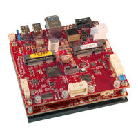
VersaLogic VL-EPU-4460 Hardware Reference Manual (63 pages)
Condor family. Intel Core 6xxx-based Embedded Processing Unit with SATA, Dual Ethernet, USB, Digital I/O, Serial, Video, Mini PCIe Sockets, SPX, Trusted Platform Module.
Brand:
VersaLogic
| Category:
Motherboard
| Size: 2 MB
Table of Contents
Cautions
4
Handling Care
4
Earth Ground Requirement
4
Table of Contents
5
Introduction
9
Figure 1. the Condor (VL-EPU-4460)
9
Features
10
Technical Specifications
10
Block Diagram
11
Figure 2. Condor (VL-EPU-4460) Block Diagram
11
Dimensions and Mounting
12
Condor Dimensions
12
Figure 3. Condor Dimensions and Mounting Holes
12
Configuration and Setup
13
Initial Configuration
13
Basic Setup
13
BIOS Setup Utility
14
Default BIOS Setup Values
14
Operating System Installation
14
Jumper Blocks
15
Jumper Configuration Summary
15
Figure 4. Jumpers As-Shipped Configuration
15
Table 1. Jumper Block Configurations
15
Board Features
16
Cpu
16
CPU die Temperature
16
System RAM
16
Real-Time Clock (RTC)
16
Table 2. Condor Memory Characteristics
16
External Connectors
17
Figure 5. Top Baseboard Connector Locations
17
Power Delivery
18
Main Power Connector
18
Figure 6. Main Power Connector Pin Orientation
18
Cabling
19
Power Requirements
19
Power Delivery Considerations
19
Table 3. Main Power Connector Pinout
19
Power Button
20
Supported Power States
20
Table 4. Supported Power States
20
Battery Power Options
21
Figure 7. Location and Pin Orientation of the Battery Connector
21
External Speaker
22
Push-Button Reset
22
Figure 8. VL-CBR-0203 Latching Battery Module
22
CPU Fan Connector
23
Figure 9. Location and Pin Orientation of the CPU Fan Connector
23
Table 5. CPU Fan Connector Pinout
23
Cabling
24
Mass Storage Interfaces
25
SATA Interface
25
Figure 10. Location of the SATA Connector
25
Multi-Purpose I/O
26
USB Interfaces
26
Figure 11. Location of the USB Ports
26
Mini Pcie Sockets
27
Figure 12. Location of Mini Pcie Sockets
27
Table 6. Mini Pcie Socket 1 / Msata Socket Pinout
28
W_DISABLE# Signal
29
Figure 13. Mini Pcie Wireless Status Leds
30
Mini Pcie Card Wireless Status Leds
30
Table 7. Mini Pcie Card Wireless Status Leds
30
Figure 14. Location of the Sata/Msata Activity LED
31
SATA Activity LED
31
User I/O Connector
32
Figure 15. Location and Pin Orientation of the User I/O Connector
32
Cabling
33
Table 8. User I/O Connector Pinout and Pin Orientation
33
SPX* Expansion Bus
34
Figure 16. SPX Connector Location and Pin Configuration
34
Cabling
35
Table 9. SPX Connector Pinout
35
Serial I/O
36
Serial Ports
36
Figure 17. Location and Pin Orientation of the Serial I/O Connectors
36
Cabling
37
COM Port Configuration
37
Serial Port Connector Pinout
37
Console Redirection
37
Table 10 COM1/COM2 Connector Pinout
37
Video Interfaces
38
Mini Displayport++ Connectors
38
Figure 18. Location of the Mini Displayport++ Connectors
39
Table 11. Mini Displayport++ Connector Pinout
39
Figure 19. VL-CBR-2032 Mini Displayport to VGA Adapter
40
VGA Output
40
LVDS Interface
41
LVDS Flat Panel Display Connectors
41
Figure 20. Location of the LVDS Connectors
41
Table 12. LVDS Flat Panel Display Connector Pinout
42
LVDS Backlight Connector
44
Table 13. LVDS Backlight Connector Pinout
44
Network Interfaces
45
Ethernet Connector
45
Figure 21. Location and Pin Orientation of the Ethernet Connector
45
Cabling
46
Table 14. Ethernet Connector Pinout
46
Ethernet Status LED
47
Figure 22. Onboard Ethernet Status Leds
47
VL-CBR-4005B Paddleboard
48
VL-CBR-4005B Connectors and Indicators
48
Figure 23. VL-CBR-4005B Connectors, Switches, and Leds
48
User I/O Connector
49
Figure 24. Location and Pin Orientation of the User I/O Connector
49
Table 15. User I/O Connector Pinout
49
Cabling
50
On-Board Battery
50
Auxiliary I/O Connector
51
Figure 25. Location and Pin Orientation of Auxiliary I/O Connector
51
Table 16. Auxiliary I/O Connector Pinout
51
Dimensions and Mounting Holes
52
Figure 26. VL-CBR-4005B Dimensions and Mounting Holes
52
Thermal Considerations
53
Selecting the Correct Thermal Solution for Your Application
53
Heat Plate
53
System-Level Considerations
53
CPU Thermal Trip Points
54
Table 17. CPU Thermal Trip Points
54
Thermal Specifications, Restrictions, and Conditions
55
Overall Restrictions and Conditions
55
Heat Plate Only Restrictions and Conditions
55
Heat Sink Only Considerations
55
Table 18. Temperature Monitoring Programs
55
Table 19. Absolute Minimum and Maximum Air Temperatures
55
Heat Sink with Fan Considerations
56
EPU-4460 Thermal Characterization
56
Table 20. EPU-4460 Thermal Testing Setup
56
Figure 27. EPU-4460-EAP Dual Core Temperature Relative to Ambient Temperature
57
Test Results
57
Figure 28. EPU-4460-EBP Dual Core Temperature Relative to Ambient Temperature
58
Installing Versalogic Thermal Solutions
59
Hardware Assembly
59
Figure 29. EPU-4460-ECP Dual Core Temperature Relative to Ambient Temperature
59
Figure 30. Heat Plate down
60
Installing the VL-HDW-416 Passive Heat Sink
61
Figure 31. Example of Heat Plate up with a Heat Sink
61
Figure 32. Installing the Passive Heat Sink
62
Installing the VL-HDW-415 Heat Sink Fan
63
Figure 33. Installing the Heat Sink Fan
63
Advertisement
Advertisement
Related Products
VersaLogic Iguana VL-EPIC-25
VersaLogic Bengal VL-EPMe-30
VersaLogic VL-EPM-31
Versalogic Lion VL-EPMe-42
VersaLogic Blackbird VL-EPU4562
VersaLogic Zebra VL-EPC-2701
VersaLogic Copperhead VL-EBX-41
VersaLogic VL-EBX-18
VersaLogic VL-EBX-38
VersaLogic VL-EBX-37
VersaLogic Categories
Motherboard
Single board computers
Computer Hardware
Control Unit
PCI Card
More VersaLogic Manuals
Login
Sign In
OR
Sign in with Facebook
Sign in with Google
Upload manual
Upload from disk
Upload from URL