Sign In
Upload
Manuals
Brands
UTC Fire and Security Manuals
Control Unit
FenwalNET 8000-ML
UTC Fire and Security FenwalNET 8000-ML Manuals
Manuals and User Guides for UTC Fire and Security FenwalNET 8000-ML. We have
1
UTC Fire and Security FenwalNET 8000-ML manual available for free PDF download: Installation, Operation And Maintenance Manual
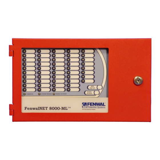
UTC Fire and Security FenwalNET 8000-ML Installation, Operation And Maintenance Manual (242 pages)
Intelligent Fire Alarm-Suppression Control Unit
Brand:
UTC Fire and Security
| Category:
Control Unit
| Size: 3 MB
Table of Contents
Foreword
3
Terms and Abbreviations
4
Safety Summary
5
Table of Contents
9
Table of Contents
10
List of Figures
13
List of Tables
17
Codes and Standards
19
General Information
19
Introduction
19
Listings and Approvals
19
Other Standards
20
Suppression System Standards
20
System Description
21
Optional Components
22
System Components
22
System Enclosure Types
22
1-7.1 Enclosure Features
23
1-8.1 Keypad/Display Features
27
Keypad and Display
27
Main Controller Board (MCB)
28
Main Controller Board Features
29
Power Supply/Pmu Assembly
29
1-10.1 Power Supply Units
30
1-10.2 Power Management Unit (PMU) Board
30
Batteries
31
1-12.1 Expansion Backplane
32
Expansion Card Cage
32
1-13.1 General Guidelines for the Use of Expansion Cards
34
1-13.2 Expansion Card Slot Addresses
34
Optional Expansion Cards
34
Optional Remote Devices
37
Remote Devices Using RS485 Bus to MCB
37
1-14.2 Remote Devices Using RS232 or USB Ports
38
1-15.1 Smartone Devices
39
Signaling Line Circuit (SLC) Devices and Modules
39
High Sensitivity Smoke Detectors
40
Smartone Addressable Modules
41
1-18.1 Remote Configuration Software
44
Optional Software
44
System Specifications
45
Chapter 2 Installation
49
Introduction
49
Preparing for Installation
49
Unpacking the System
49
2-2.2 Materials/Tools Required
50
2-2.3 Determining Wall Location
50
2-2.4 Removing Knockouts from Enclosure
50
Installing Conduit
51
Installing Electrical Boxes
51
Overview of Installation Steps
51
Step One: Shut off AC Power
51
Step Two: Prepare the Enclosure and Electrical Wiring
51
Step Three: Mount the Enclosure
51
Step Four: Install the Top Tier Power Supply/Pmu Assembly and MCB
51
Step Five: Install Expansion Card Cage and Included Cards (if Applicable)
51
2-3.6 Step Six: Install Batteries
52
2-3.7 Step Seven: Install Expansion Enclosures And/Or Remote Modules (if Applicable)
52
2-3.8 Step Eight: Auto-Configuring the System
52
2-3.9 Step Nine: Uploading the Configuration File and Performing the Pre-Test
52
2-3.10 Step Ten: Performing Final System Test and Commissioning the System
52
2-3.11 Step Eleven: Installing the Actuation Devices and Extinguishing System
52
2-3.12 Step Twelve: Performing Final Installation Procedures
52
Standard System Installation Procedure
53
2-4.1 Surface Mounting of Main or Expansion Enclosures
53
2-4.2 Semi-Flush Mounting of Main or Expansion Enclosures
54
Installing a Power Supply Unit into the Enclosure Top Tier
56
2-4.4 Installing the Power Management Unit (PMU) Board into Enclosure Top Tier
57
2-4.5 Installing the Audible PMU Trouble Sounder
61
2-4.6 Making AC Power Source and Earth Ground Connections
63
2-4.7 Installing the Main Controller Board into Enclosure Top Tier
65
Replacing Enclosure Door
67
Making Internal 24Vdc Power Connections
68
Making Internal Communication Connections
69
Optional Equipment Installation Procedure
70
Installing the Expansion Card Cage
70
2-7.2 Inserting and Securing an Expansion Card
72
2-7.3 Installing Add-On Power Supply/Pmu Assembly with Bracket
73
2-7.4 Installing the Battery Tray
74
2-7.5 Connecting Standby Batteries to PMU Board
75
Setting up Wiring to Field Devices
76
2-8.1 Installing Electrical Wiring and Making Connections
76
2-8.2 Overview of SLC Wiring Styles
76
2-8.3 Electrical Supervision
76
2-8.4 Wiring Auxiliary Power Outputs
77
2-8.5 Wiring Signaling Line Circuits
77
2-8.6 Wiring Notification Appliance Circuits
83
Wiring R-NAC (Combination) Circuits
85
2-8.8 Relay Outputs
90
2-8.9 City Tie Wiring
91
Setting up Communications
92
2-9.1 Setting up RS232 Communications Port
92
2-9.2 Setting up USB Communications Ports
93
2-9.3 Connecting a Laptop, Remote Computer or Printer
93
Setting up Peripheral Devices and Enclosures
94
Installing the Remote Enclosure
95
Installing the Large Capacity Battery Cabinet
100
Configuration and Programming
101
Introduction
101
Initial Signaling-Line Circuit Configuration
101
3-1.2 Site-Specific Programming
103
Menu Operation
104
Overview of Main Menu Functions
104
3-3.1 Isolate Menu Functions
106
3-3.2 List Menu Functions
110
3-3.3 Set Menu Functions
115
Test Menu Functions
138
Chapter 4 Operation
147
Introduction
147
Operating States
147
4-2.1 the Event Output Control (EOC) Program
148
User Interface Keys and Functions
148
Operator Control Keys
149
Alphanumeric Keypad
149
Status-Indicating Leds
150
LCD Panel System Status Messages
151
Using Passwords for System Security
151
4-8.1 Levels of Security
151
4-8.2 Default Passwords
152
4-8.3 Entering Passwords
152
System Startup Procedure
152
4-9.1 Preliminary Procedures
152
Initial Power-Up
153
Fenwalnet 8000-ML System Operation Overview
156
4-10.1 Normal Operation
156
4-10.2 Trouble State
156
4-10.3 Alarm State
158
Supervisory State
163
4-10.5 Pre-Alarm State
164
4-10.6 Concurrent States
166
Testing and Maintenance
173
Introduction
173
Semi-Annual and Annual Testing
173
Lamp Test
173
Battery Test
173
5-2.3 Initiating-Devices Test
174
5-2.4 Walk Test
174
MCB Clock Battery Replacement
174
Testing Frequency
175
Fuse Replacement
175
Chapter 6 Troubleshooting
177
Introduction
177
Available Parts
199
Appendix Abattery and Power Supply Calculations
203
APPENDIX B- Wiring Requirements for Fenwalnet 8000-ML Signaling Line Circuit
211
Appendix Clist of Agency Listed Compatible Devices
213
Appendix Dfm Rules for Preaction/Deluge Systems
217
Appendix Eroutings for Power-Limited and Non-Power- Limited Wiring
219
Appendix Ffenwalnet 8000-Ml for Canadian Applications
227
Canadian Application-Style Enclosures
227
Installation
228
Appendix Gfenwalnet 8000-Ml for City of Chicago Applications
229
Introduction
229
Overview of the Stand-Alone Control Box
230
Fire Alarm Trouble
230
G-2.2 City Tie Trouble
231
G-2.3 City Disconnect Switch
231
Installation and Connections
231
Appendix Hconversion Instructions for Fenwalnet 2000
233
Introduction
233
Fenwalnet 2000 Control Unit Retrofit Kit
233
Conversion Parts
233
H-2.2 Operational Parts
234
Optional Parts (Not Included in Retrofit Kit
234
Tools Required
234
Preparation
234
Procedure
235
Index
237
Advertisement
Advertisement
Related Products
UTC Fire and Security Interlogix NX-535N
UTC Fire and Security Interlogix NX-535N-V3
UTC Fire and Security interlogix TR3010
UTC Fire and Security interlogix TR3010-R3
UTC Fire and Security interlogix TR3020WDM
UTC Fire and Security interlogix TR3020WDM-R3
UTC Fire and Security interlogix TR3030
UTC Fire and Security interlogix TR3030-R3
UTC Fire and Security Categories
Control Unit
Security Sensors
Controller
Security System
Smoke Alarm
More UTC Fire and Security Manuals
Login
Sign In
OR
Sign in with Facebook
Sign in with Google
Upload manual
Upload from disk
Upload from URL