Sign In
Upload
Manuals
Brands
TOYOTA Manuals
Automobile
ZZT230 series
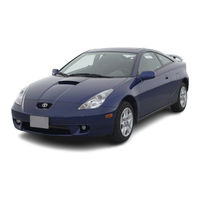
TOYOTA ZZT230 series Manuals
Manuals and User Guides for TOYOTA ZZT230 series. We have
3
TOYOTA ZZT230 series manuals available for free PDF download: Repair Manual, Wiring Diagram, Manual
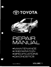
Toyota ZZT230 series Repair Manual (821 pages)
Brand:
Toyota
| Category:
Automobile
| Size: 18 MB
Table of Contents
Introduction M
5
Table of Contents
5
How to Use this Manual
6
Identifi C Ati O N Informati O N
8
Vehicle Identification and
8
Engine Serial Number
8
Repair Instructions
9
Vehicle Lift and Support Locations
13
Controlled Systems
24
How to Proceed Troubleshooting
25
And Inspection Procedure
35
How to Use the Diagnostic Chart
35
Abbreviations Used in this Manual
40
Glossary of Sae and Toyota Terms
45
Outside Vehicle
50
Inside Vehicle
51
Under Hood
53
Brake
55
Chassis
56
Preparation
58
Maintenance
60
Engine Mechanical
61
Emission Control
66
Sfi
67
Cooling
70
Lubrication
74
Ignition
78
Starting
80
Charging
83
Clutch
86
Manual Transaxle (C56
94
Manual Transaxle (C60
97
Automati C Transaxle (U240E
105
Automati C Transaxle (U341E
110
Suspension and Axle
115
Brake
121
Steering
126
Supplemental R Estraint System
133
Body Electrical
136
Body
139
Air Conditioning
144
Air Conditioning
208
Diagnostics -
210
Engine
212
How to Proceed with Troubleshooting
212
Customer Problem Analysis Check
213
Pre-Check
214
Diagnostic Trouble Code Chart
225
Parts Location
230
Terminals of Ecm
231
Problem Symptoms Table
233
Automatic Transaxle (U240E)
366
How to Proceed with
366
Troubleshooting
366
Customer Problem Analysis Check
367
Pre-Check
368
Diagnostic Trouble Code Chart
379
Parts Location
380
Terminals of Ecm
381
Problem Symptoms Table
383
Circuit Inspection
386
Indicator Light
428
Automatic Transaxle (U341 E)
429
How to Proceed with Troubleshooting
429
Customer Problem Analysis Check
430
Pre-Check
431
Diagnostic Trouble Code Chart
442
Parts Location
443
Terminals of Ecm
444
Problem Symptoms Table
445
Electronic Brake Force Distribution (Ebd
485
How to Proceed with Troubleshooting
485
Customer Problem Anal Y$1$ Check
486
Pre-Check
487
Diagnostic Trouble Code Chart
491
Parts Location
492
Terminals of Ecu
493
Circuit Inspection
496
Supplemental Restraint Systemd
535
Troubleshooting
693
Cruise Control System
694
Customer Problem Analysis Check
695
Pre-Check
696
Diagnostic Trouble Code Chart
701
Parts Location
702
Terminals of Ecu
703
Body Control
747
Parts Location
748
Problem Symptoms Table
753
Illuminated Entry
753
Circuit Inspection
755
Multiplex Communication Circuit
811
Advertisement
TOYOTA ZZT230 series Wiring Diagram (232 pages)
ZZT 230, 231 Series
Brand:
TOYOTA
| Category:
Automobile
| Size: 3 MB
Table of Contents
How to Use this Manual
3
Stop Light
4
Ground Points Circuit Diagrams
8
Currtnt Flow Chart Intended Use
9
K Connector List
10
Part Number of Connectors
11
Troubleshooting
12
Voltage Check
12
Continuity and Resistance Check
12
Finding a Short Circuit
13
Disconnection of Male and Female Connectors
13
How to Replace Terminal (with Terminal Retainer or Secondary Locking Device)
14
Terminal Retainer
15
Abbreviations
17
Glossary of Terms and Symbols
18
Relay Locations - Engine Compartment/Instrument Panel
20
Relay Locations - Body
21
Relay Locations - Engine Room J/B
22
Relay Locations - Instument Panel J/B
24
Relay Locations - Engine Room R/B #1
26
Relay Locations - Engine Room R/B #2
27
Relay Locations - Engine Room J/B Inner Circuit
28
Relay Locations - Instrument Panel J/B Inner Circuit
30
Electrical Wiring Routing - Position of Parts in Engine Compartment [1ZZ-FE]
32
Starter S
33
Electrical Wiring Routing - Position of Parts in Engine Compartment [2ZZ-GE]
34
Position of Parts in Instrument Panel
36
Position of Parts in Body
38
Location of Connector Joining Wire Harness and Wire Harness [1ZZ-FE]
40
Location of Ground Points/Splice Points [1ZZ-FE]
40
Connector Joining Wire Harness and Wire Harness
41
Location of Connector Joining Wire Harness and Wire Harness [2ZZ-FE]
42
Location of Ground Points/Splice Points [2ZZ-FE]
42
Connector Joining Wire Harness and Wire Harness [2ZZ-FE]
43
Location of Connector Joining Wire Harness and Wire Harness
44
Location of Ground Points
44
Power Source
50
Power Source - Service Hints
52
Starting and Ignition
54
Starting and Ignition
56
Service Hints
56
Parts Location/Relay Blocks
56
Junction Block and Wire Harness Connector/Connector Joining Wire Harness and Wire Harness
56
Starting and Ignition - Ground Points
57
Charging
58
Charging - Service Hints
59
Engine Control Diagram
60
Engine Control/System Outlineinput Signals
66
Control/Diagnosis/Fail-Safe System
67
Engine Control - Service Hints
68
Engine Control - Parts Location
69
Headlight Diagram
72
Headlight - System Outline/Service Hints/Parts Location
74
Fog Light Diagram
76
Fog Light - Service Hints/Parts Location
77
Taillight Diagram
78
Taillight - Service Hints/Parts Locations
80
Illumination
82
Illumination - Service Hints/Parts Location
84
Interior Light Diagram
86
Interior Light - System Outline/Service Hints/Parts Location
87
Back-Up Light Diagram
88
Back-Up Service Hints/Parts Locations
89
Stop Light Diagram
90
Stop Light - Service Hints/Parts Location
91
Turn Signal and Hazard Warning Light Diagram
92
Turn Signal and Hazard Warning Light - Service Hints/Parts Location
93
Light Reminder Buzzer Diagram
94
Light Reminder Buzzer - System Outline/Service Hints/Parts Location
95
Multiplex Communication System (Communication Bus) Diagram
96
Multiplex Communication System - Systems List
97
Multiplex Communication System Diagram
98
Multiplex Communication System - Service Hints/Parts Location
106
Wireless Door Lock Control Diagram
108
Wireless Door Lock Control - System Outline/Service Hints/Parts Location
110
Door Lock Control Diagram
112
Door Lock Control - System Outline/Service Hints/Parts Location
114
Power Window Diagram
116
Power Window - System Outline/Service Hints/Parts Location
118
Moon Roof Diagram
120
Moon Roof System Outline/Service Hints/Parts Location
121
Electric Tension Reducer Diagram
122
Electric Tension Reducer - Service Hints/Parts Location
123
Key Reminder and Seat Belt Warning Diagram
124
Key Reminder and Seat Belt Warning - System Outline/Service Hints/Parts Location
126
SRS Diagram
128
SRS - System Outline/Parts Location
130
ABS Diagram
132
ABS - System Outline/Service Hints/Parts Location
134
Cruise Control Diagram
136
Cruise Control - System Outline
138
Cruise Control - Service Hints/Parts Location
139
Electronically Controlled Transmission and A/T Indicator Diagram
140
Electronically Controlled Transmission and A/T Indicator - System Outline/Service Hints/Parts Location
144
Shift Lock Diagram
146
Shift Lock - Service Hints/Parts Location
147
Horn Diagram
148
Horn - Service Hints/Parts Location
149
Cigarette Lighter and Clock Diagram
150
Cigarette Lighter and Clock - Service Hints/Parts Location
151
Remote Control Mirror Diagram
152
Remote Control Mirror - Service Hints/Parts Location
153
Front Wipe and Washer Diagram
154
Front Wiper and Washer - System Outline/Service Hints/Parts Location
156
Rear Wiper and Washer Diagram
158
Rear Wiper and Washer - System Outline/Service Hints/Parts Location
159
Rear Window Defogger Diagram
160
Rear Window Defogger - Service Hints/Parts Location
161
Radio and Player (Separate Type Amplifier) Diagram
162
Radio and Player (Separate Type Amplifier) - Service Hints/Parts Location
164
Radio and Player (Built-In Type Amplifer) Diagram
166
Radio and Player (Built-In Type Amplifer) - Service Hints/Parts Location
167
Combinatin Meter Diagram
168
Combination Meter - Service Hints/Parts Location
172
Radiator Fan and Condenser Fan Diagram
174
Radiator Fan and Condenser Fan - System Outline/Service Hints/Parts Location
175
Air Conditioning Diagram
176
Air Conditioning - System Outline/Service Hints/Parts Location
178
I Ground Point Diagram
180
I Ground Point - Parts Location
184
Power Source (Current Flow Chart)
186
Power Source (Current Flow Chart) - Table
188
Electronically Controlled Transmission and A/T Indicator
188
Instrument Panel J/B Table
189
Cigarette Lighter and Clock
189
Connector List - Diagrams
192
Celica (Ewd432U)
194
Part Number of Connectors - Table
200
Overall Electrical Wiring Diagram
202
Overall Electrical Wiring Diagram - System Index
204
1 Celica Electrical Wiring Diagram
205
2 Celica Electric Wiring Diagram
209
3 Celica Electric Wiring Diagram
212
4 Celica Electric Wiring Diagram
214
5 Celica Electric Wiring Diagram
215
6 Celica Electric Wiring Diagram
216
7 Celica Electric Wiring Diagram
217
8 Celica Electric Wiring Diagram
218
9 Celica Electric Wiring Diagram
219
10 Celica Electric Wiring Diagram
220
11 Celica Electric Wiring Diagram
221
12 Celica Electric Wiring Diagram
222
13 Celica Electric Wiring Diagram
223
14 Celica Electric Wiring Diagram
224
15 Celica Electric Wiring Diagram
225
16 Celica Electric Wiring Diagram
226
17 Celica Electric Wiring Diagram
227
18 Celica Electric Wiring Diagram
228
19 Celica Electric Wiring Diagram
230
20 Celica Electric Wiring Diagram
231
Toyota ZZT230 series Manual (106 pages)
Brand:
Toyota
| Category:
Automobile
| Size: 7 MB
Table of Contents
General Repair Instructions
3
Work Precautions
3
How to Use this Manual
7
Preparation for Installation
12
Installation
13
Abbreviations Used in this Manual
19
Radiator Support (Assy)
20
Front Crossmember (Assy)
25
Front Fender Front Apron (Assy)
31
Cowl Top Side Panel (Assy)
33
Front Fender Apron (Assy)
35
Front Side Member (Cut-P)
38
Front Side Member (Assy)
41
Front Body Pillar (Cut)
46
Front Door Outer Panel (Assy)
50
General Information
91
Engine Compartment
98
Rear Luggage Compartment
100
Door Parts
101
Advertisement
Advertisement
Related Products
Toyota ZZT231 series
Toyota Avensis ZZT251 2003
Toyota Avensis ZZT250 2003
Toyota Avensis ZZT250 2004
Toyota Avensis ZZT251 2004
Toyota Avensis ZZT251 2005
Toyota Avensis ZZT250 2006
Toyota Avensis ZZT251 2007
Toyota Avensis ZZT250 2007
Toyota Avensis ZZT250 2008
TOYOTA Categories
Automobile
Automobile Accessories
Car Navigation system
Sewing Machine
Engine
More TOYOTA Manuals
Login
Sign In
OR
Sign in with Facebook
Sign in with Google
Upload manual
Upload from disk
Upload from URL