Sign In
Upload
Manuals
Brands
Tektronix Manuals
Monitor
WFM 601E
Tektronix WFM 601E Manuals
Manuals and User Guides for Tektronix WFM 601E. We have
2
Tektronix WFM 601E manuals available for free PDF download: Service Manual, User Manual
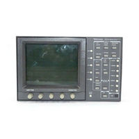
Tektronix WFM 601E Service Manual (368 pages)
Serial Digital Component Waveform Monitor
Brand:
Tektronix
| Category:
Monitor
| Size: 4 MB
Table of Contents
Table of Contents
7
Table 1-1: Electrical Specifications
24
Table 1-2: CRT Display
31
Table 1-3: AC Power Source
31
Table 1-4: Environmental Characteristics
32
Table 1-5: Physical Characteristics
32
Table 1-6: Safety Standards
32
Table 1-7: Safety Certification Compliance
33
Table 1-8: Certifications and Compliances
34
Figure 2-1: Dimensions of the 1700F00 Cabinet
38
Figure 2-2: 1700F02 Portable Cabinet
39
Figure 2-3: Rear View of the Waveform Monitor in a 1700F00
40
Figure 2-4: the 1700F05 Rack Cabinet Holds Two Instruments
41
Figure 2-5: 1700F05 Cabinet Showing Utility Drawer and Blank Panel
42
Figure 2-6: the WFM 601M Waveform Monitor Front Panel
45
Figure 2-7: Elements of the Waveform Monitor Menu Controls
49
Figure 2-8: Rear Panel of the Waveform Monitor
50
Figure 2-9: Pin Assignments for the RS-232 Connector
51
Table 2-1: Remote Connector Pin Assignments and Functions
52
Figure 2-10: Pin Assignments for the REMOTE Connector
52
Figure 3-1: Power Supply Block Diagram
61
Figure 4-1: Audio Cable Adapter
67
Figure 4-2: Timing Cursors
75
Figure 4-3: HF Bowtie Magnified to Measure Null Offset
82
Figure 4-4: Arrowhead Gamut Check
83
Table 4-1: Audio Values
88
Figure 5-1: Jumper Cable Adapter
94
Figure 5-2: Minimum Configurations for Remote Communications
95
Table 5-1: List of Special Equipment and Where It Is Used
96
Figure 5-3: Typical Display of the Adjustment Procedures
98
Table 5-2: Signals Required for Adjustment Procedure
101
Figure 5-4: Location of Circuit Boards
106
Figure 5-5: A1 Power Supply Board
106
Figure 5-6: A3 Main Board
107
Figure 5-7: A5 Serial Board
107
Figure 5-8: A7 Component Board
108
Figure 5-9: Trace Rotation, y Alignment, and Geometry - Horizontal Center Marks
108
Figure 5-10: Post Readout, Offset, and Gain
109
Figure 5-11: Monitor out Yoffset
109
Figure 5-12: Gamut Limit - Strobe Pulses
110
Figure 5-13: On-Screen Frequency Response
110
Figure 5-14: Bowtie Timing
111
Figure 5-15: Electronic Graticule Adjustment
111
Figure 5-16: Diamond Eye Opening
112
Table 6-1: Static Susceptibility
122
Table 6-2: Circuit Board Functional Names
145
Table 6-3: Power Supply Fault Symptoms
147
Table 6-4: Low Volts Supply Voltages
148
Table 6-5: Control Circuit Test Points
149
Table 6-6: Shut down Logic Levels
151
Table 6-7: High Volts Supply Fault Symptoms
151
Table 6-8: High-Voltage Oscillator Test Points
152
Table 6-9: Adjustment Required after Repairing Circuit Boards
155
Table 6-10: Remote Communication Parameters
158
Table 6-11: Adjustment and Verification Required after an Upgrade or Configuration
166
Table 9-1: A4 Input Board Component Locator
276
Table 9-2: A4A1 BNC Board Component Locator
276
Table 9-3: WFM 601M A5 Serial Board (Front) Component Locator
278
Advertisement
Tektronix WFM 601E User Manual (218 pages)
Serial Digital Component Waveform Monitors
Brand:
Tektronix
| Category:
Microphone
| Size: 4 MB
Table of Contents
Table of Contents
7
Figure 1-1: Dimensions of the 1700F00 Plain Cabinet
25
Figure 1-2: 1700F02 Portable Cabinet
26
Figure 1-3: Rear View of the Waveform Monitor in a 1700F02 Cabinet
27
Figure 1-4: the 1700F05 Rack Cabinet Holds Two Instruments
28
Figure 1-5: 1700F05 Cabinet Showing Utility Drawer and Blank Panel
29
Figure 1-6: Monitoring the Video Bit Stream of a Serial Receiver
31
Figure 1-7: Monitoring Serial Digital Signals Around a Routing Switcher
32
Figure 1-8: Eye Pattern Display of a Termination with Good Return Loss
33
Figure 1-9: Eye Pattern Display of a Termination with Poor Return Loss
33
Figure 1-10: Initial Equipment Connections
35
Figure 1-11: Initial Display in the Waveform Display Mode
37
Figure 1-13: Eye Pattern Display Mode
39
Figure 1-14: Jitter Display Mode
40
Figure 1-17: Arrowhead Gamut Display
42
Figure 1-18: Diamond Gamut Display
43
Figure 1-19: Video Digital Waveform
44
Figure 1-20: Data Digital Waveform
45
Figure 1-21: Typical Audio Display with Small Phase Error
45
Figure 2-1: WFM 601M Front Panel
48
Figure 2-2: WFM 601A and WFM 601E Front Panels
49
Figure 2-3: Elements of the Waveform Monitor Menu Controls
52
Figure 2-4: Rear Panel of the Waveform Monitor
53
Figure 3-1: a Signal from One Channel Only
58
Figure 3-2: X and y Signal in Phase with Equal Amplitudes
59
Figure 3-3: Signals out of Phase with Equal Amplitudes
59
Figure 3-4: Signals out of Phase with Unequal Amplitudes
60
Figure 3-5: Signals with Reverse Polarity and Equal Amplitudes
60
Figure 3-6: Signals with a Phase Error of 90 Degrees and
60
Figure 3-7: Typical Audio Display Pattern with Small Phase Error
61
Table 3-1: List of Measured and Actual Rise Times for the Waveform Monitor
82
Serial Status
101
Sweep
109
Vector Display Modes
110
Video in
115
Waveform Display
115
Appendices
116
Appendix A: Specifications
118
Table A-1: Electrical Specifications
118
Table A-2: CRT Display
125
Table A-3: AC Power Source
126
Table A-4: Environmental Characteristics
126
Table A-5: Physical Characteristics
126
Table A-6: Safety Standards
127
Table A-7: Safety Certification Compliance
127
Table A-8: Certifications and Compliances
128
Appendix B: Remote Operation
130
RS-232 Connector
130
Remote Connector
130
Table B-1: Remote Connector Pin Assignments and Functions
131
Appendix C: Remote Command Set
134
Table C-1: Symbols Used in this Section
134
Cable Measurement Commands
136
Slm:cable <B8281 | B1694 | B1505> (WFM 601E and WFM 601M Only
136
SLM:SOURCE? (WFM 601E and WFM 601M Only
137
SLM:RCVR? (WFM 601E and WFM 601M Only
137
SLM:LEVEL? (WFM 601E and WFM 601M Only
138
SLM:LENGTH? (WFM 601E and WFM 601M Only
138
Configuration Commands
139
Reference: MODE <INT | EXT
139
Arrowhead:limit:pal <MV_700 | MV_950
140
Arrowhead:format <NTSC | PAL | AUTO
141
Gamut:graticule <Arrowhead | Diamond
141
Gamut:alarm:trigger <NONE | CMPST | RGB | both
142
Gamut:alarm:display <SCRN | PICT | both
142
Standard <LINES_525 | LINES_625 | AUTO
143
Vector:bars <B100 | B75
143
Vector:graticule <LTNG | Vector
144
Serial:menu <STATUS | FORM | CABLE
144
Serial:display <RGB | Ypbpr
145
Serial:monitor <GBR | Ypbpr
145
Serial:eavsav <PASS | STRIP
146
Serial:alarm:<Error Type> <Alarm Setting
146
Uimenu:<Command> <Options
147
Table C-2: Serial:alarm: Commands and Options
147
Table C-3: UIMENU: Commands and Options
148
Cursor Commands
149
Cursor:select <VOLT | TIME | VOLT_TIME | MARK | NONE
149
Cursor:control <VOLT | TIME
150
MC:<ONE | TWO | THREE> <Marker Position
150
VC | TC>:<ONE | TWO> <Voltage Level | Timing Range
151
Table C-4: Voltage and Timing Cursor Positioning Commands and Options
151
Tc | VC>:Track <On | off
152
Table C-5: Voltage and Timing Cursor Tracking Commands and Options
152
Digital Waveform and Digital List Commands
153
DGTL? (WFM 601M Only
153
Dgtl:region? (WFM 601M Only
154
DGTL:DATA? (WFM 601M Only) DGTL:DATA:V
154
DGTL:VDATA? (WFM 601M Only
155
Dgtl:vidmode <VIDEO | DATA> (WFM 601M Only
156
Dgtl:freeze <ON | OFF> (WFM 601M Only
156
DGTL:BASE <HEX | DECIMAL | BINARY> (WFM 601M Only
157
Table C-6: Display:single Commands
158
Table C-7: Display:intensity Command Options
160
Table C-8: Display:focus Command Options
163
Table C-9: Typical ALLEV? Responses to Detected System Errors
165
Table C-10: Lineselect: Commands and Options
175
Table C-11: Position:vertical Commands and Options
178
Table C-12: Position:horz Commands and Options
178
Table C-13: Filter Command Options
184
Advertisement
Related Products
Tektronix WFM601
Tektronix WFM6120
Tektronix WFM6100 Opt. MB
Tektronix WFM 601i
Tektronix WFM61UP FP
Tektronix WFM 601A
Tektronix WFM91D
Tektronix WFM71UP FP
Tektronix WFM820UP
Tektronix WFM700 Series
Tektronix Categories
Test Equipment
Measuring Instruments
Amplifier
Portable Generator
Printer
More Tektronix Manuals
Login
Sign In
OR
Sign in with Facebook
Sign in with Google
Upload manual
Upload from disk
Upload from URL