Sign In
Upload
Manuals
Brands
Tektronix Manuals
Measuring Instruments
RFM150
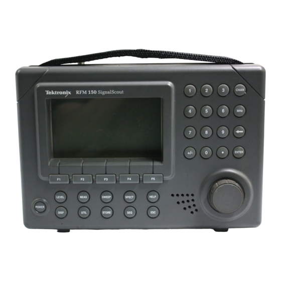
Tektronix RFM150 Manuals
Manuals and User Guides for Tektronix RFM150. We have
2
Tektronix RFM150 manuals available for free PDF download: Instruction Manual, User Manual
Tektronix RFM150 Instruction Manual (278 pages)
SignalScout
Brand:
Tektronix
| Category:
Measuring Instruments
| Size: 1 MB
Table of Contents
Table of Contents
5
Figure 1-1: the Sweep Display
10
General Safety Summary
15
Service Safety Summary
18
Preface
19
Documentation Conventions
20
Getting Started
21
Product Description
23
Compatibility
23
Level Measurement Modes
23
Other Operating Modes
24
User Interface
24
Automated Test Sequences
24
Results Storage / Printing
25
Options
25
Rugged Construction
25
Accessories
26
Tutorial
27
Figure 1-2: Spectrum Display with Knob Assigned to Reference Level
37
Figure 1-3: RS232 Menu Showing Factory Settings
42
Figure 1-4: PRINTER Menu Showing Factory Settings
43
Figure 1-5: Printout of 1 Channel Measurement
44
Operating Basics
45
Functional Overview
47
Connectors
47
Figure 2-1: Top View of the RFM 150, Showing Connector
47
Controls and Indicators
48
Figure 2-2: the RFM 150 Front Panel, Showing Controls
48
Menu Hierarchy
51
Figure 2-3: Menu Hierarchy
51
Figure 2-3: Menu Hierarchy (Cont.)
52
Figure 2-3: Menu Hierarchy (Cont.)
53
Explanation of Readouts
54
Figure 2-4: Display Readouts and Labels
55
Tuning
56
Editing Methods
57
Figure 2-5: Sample Menu Screen Showing Use of the Outline
57
Figure 2-6: Sample Menu Screen Showing Text Editing
58
Making Measurements
61
Channel Mode
62
Table 2-1: Functions of Active Keys in 1 Channel Mode
62
Figure 2–7: the 1 Channel Mode (Analog Channel)
63
Figure 2–8: the 1 Channel Mode (Digital Channel)
65
Pilots Mode
66
Figure 2-9: the Pilots Mode Display
66
Table 2-3: Functions of Active Keys in Pilots Mode
66
Channel Mode
68
Figure 2-10: the 5 Channel Mode Display
68
Table 2-4: Functions of Active Keys in 5 Channel Mode
68
All Channel Mode
70
Figure 2-11: the All Channel Mode Display
70
Table 2-5: Functions of Active Keys in All Channel Mode
71
Meter Mode
73
Table 2-6: Functions of Active Keys in Meter Mode
73
Figure 2-12: the Meter Mode Display
74
Carrier-To-Noise Ratio
76
Table 2-7: Functions of Active Keys in C/N Measurement
76
Figure 2-13: the Carrier-To-Noise Measurement Screen (Analog Channel)
77
Figure 2-14: the Carrier-To-Noise Measurement Screen (Digital Channel)
78
Hum
79
Figure 2-15: the Hum Measurement Mode Display
79
Table 2-8: Functions of Active Keys in Hum Measurement
79
FM Deviation
81
Table 2-9: Functions of Active Keys in FM Deviation
81
Figure 2-16: the FM Deviation Measurement Mode Display
82
Executing Sequences
83
Table 2-2
83
Figure 2–18: Execute Sequence Menu
84
Spectrum Mode
85
Table 2-10: Functions of Active Keys in Spectrum Mode
85
Sweep Mode
88
Table 2-11: Functions of Active Keys in Sweep Display
88
Figure 2–21: the Sweep LVL/REF Submenu Display
90
Figure 2–22: Reference Menu
91
Reference
93
Channel Tables
95
Figure 3–1: Channel Tables Menu
96
Table 3-1: Channel Table Fields for Editing
97
Clock
100
Clone Configuration
101
Display Adjustment
102
Help
103
Power Mode
105
Table 3-2: POWER Key Modes
105
Figure 3–4: the Sleep State Query Screen
106
Power up / Power down Modes
107
Powering up from an AC Source
108
Presets
108
Figure 3–6: Assign Preset Menu
109
Figure 3–7: Editing Preset F1
110
Printing Stored Measurement Results
111
Probe Loss
113
Sequences (Adding and Deleting)
114
Site Name
116
Stored Measurement Results
118
Figure 3–11: Additional Information Screen for 5 Channel Measurement Type
119
Figure 3–12: the Print in Progress Message
120
Temperature
121
Units
122
Specifications
123
Table 4-1: Input Signal Requirements
126
Table 4-2: Measurement Accuracy
126
Table 4-3: Measurement Repeatability
128
Table 4-4: Spectral Display Mode
129
Table 4-5: RF Input
129
Table 4-6: DC Jack Input
130
Table 4-7: AC Power Source
130
Table 4-8: Internal Nicad Battery
130
Table 4-9: Environmental Characteristics
131
Table 4-10: Physical Characteristics
132
Table 4-11: Certification
132
Performance Check
137
Required Equipment
141
Signal Characterization
142
Performance Check Procedure
144
Front Panel / Backlight / Clock Operation Check
146
Figure 5–4: Level Menu Function Key Assignments
147
Figure 5–7: Store Menu Function Key Assignments
148
Communications Port Function Check
149
Maintenance
151
Instrument Disassembly
153
Replacement Procedures
153
Figure 6–1: Separating the Instrument into Two Parts
155
Replacing the Calibrated Board Set
156
Figure 6–2: Removing the LCD Display Module
157
Encoder, or Keypads
158
Replacing the Front Panel Circuit Board Assembly, Speaker
158
Figure 6-3: the Front of the RFM150 as Seen from the
159
Figure 6-5: Removing the Back Board Circuit Board
168
Figure 6–6: Positioning the Ribbon Cable
168
Figure 6–7: Installing the RF Connector
169
Recharging the Battery
171
Cleaning the Instrument
173
Exterior Cleaning
173
Interior Cleaning
174
Replaceable Electrical Parts
177
Parts Ordering Information
179
Using the Replaceable Parts List
180
Replaceable Mechanical Parts
185
Parts Ordering Information
187
Using the Replaceable Parts List
188
Inside
159
Replacing the LCD Display Module
161
Figure 6–4: Removing the LCD Display Module
162
Replacing the Back Board Circuit Board Assembly
163
Figure 6–5: Removing the Back Board Circuit Board Assembly
164
Replacing the Battery
165
Instrument Assembly
167
Appendices
197
Appendix A: Channel Tables
199
Table 5-1: Test Record for RFM150
201
Table A–1: Catv–Standard
201
Table A–2: CATV–500 Channel Table
207
Table A–3: Broadcast Channel Table
211
Table A–4: CATV–HRC Channel Table
215
Table A–5: CATV–IRC Channel Table
219
Table A–6: China–Dk Channel Table
223
Table A–7: Europe–Bg Channel Table
225
Table A–8: Europe–Dk Channel Table
229
Table A–9: Europe–I Channel Table
233
Table A–10: France–L Channel Table
235
Table A–11: Japan–M Channel Table
239
Table A–12: Custom Channel Table Worksheet
243
Appendix B: Remote Communications
245
Communicating with Another RFM150
245
Figure 8-1: Exploded View of the RFM150
246
Figure B-3: UTIL Menu
250
Figure B–4: RS232 Menu Showing Factory Settings
250
Figure B–1: RS232 Menu Showing Factory Settings
246
Figure B–2: Top View of RFM 150, Showing the Interface Port
247
Communicating with a Computer (Using the CSS150
248
Communicating with a Printer
249
Appendix C: Printed Report Formats
251
Line Length
251
Channel Measurement
253
Pilots Measurement
255
Channel Measurement
256
Meter Measurement
257
All Channel Measurement
258
Figure C–5: Partial Printed Report of All Channel Measurement
259
Carrier-To-Noise Measurement
260
Figure C–6: Printed Report of Carrier-To-Noise Measurement
261
Hum Measurement
262
FM Deviation Measurement
263
Off-Channel Stored Measurement
264
Spectrum Measurement
265
Sweep Measurement
266
Figure C–11: Partial Printed Report of Sweep Measurement
267
Sequence Measurements
268
Advertisement
Tektronix RFM150 User Manual (190 pages)
Brand:
Tektronix
| Category:
Measuring Instruments
| Size: 24 MB
Table of Contents
Table of Contents
11
Eee Eee
51
Ee Eee
51
Figure 2-3: Menu Hierarchy for Measurement Modes
52
Figure 2-4: Commonly-Used Display Readouts and Labels
54
Figure 2-6: the Pilots Mode Display
59
Table 2-2: Key Actions in Pilots Mode
59
Figure 2-7: the 5 Channel Mode Display
61
Table 2-3: Key Actions in 5-Channel Mode
61
Figure 2-8: the All Channel Mode Display
63
Table 2-4: Key Actions in All-Channel Mode
64
Table 2-5: Key Actions in Meter Mode
67
Figure 2-10: the Carrier-To-Noise Measurement Screen
69
Table 2-6: Key Actions in Carrier-To-Noise Measurement Mode
69
Figure 2-11: the Hum Measurement Mode Display
71
Table 2-7: Key Actions in Hum Measurement Mode
71
Figure 2-12: the FM Deviation Measurement Mode Display
73
Table 2-8: Key Actions in FM Deviation Measurement Mode
73
Figure 2-14: Execute Sequence Menu
75
Table 2-9: Key Actions in Spectrum Mode
77
Figure 2-17: the Sweep LVL/REF Submenu Display
80
Table 2-10: Key Actions in Sweep Display Mode
81
Table 3-1: Channel Table Fields for Editing
92
Table A-1: Input Signal Requirements
118
Table A-2: Measurement Accuracy
118
Table A-3: Measurement Repeatability
120
Table A-4: Spectral Display Mode
121
Table A-8: Internal Nicad Battery
122
Table A-9: Environmental Characteristics
123
Table A-11: Physical Characteristics
124
Table C-1: Pin Assignments for Interface Port
167
Advertisement
Related Products
Tektronix SignalScout RFM151
Tektronix RF Scout
Tektronix RSA3308A
Tektronix RSA5103B
Tektronix RSA5106B
Tektronix RSA5126B
Tektronix RSA5115A
Tektronix RSA7100 Series
Tektronix RSA3408
Tektronix RSA3000A Series
Tektronix Categories
Test Equipment
Measuring Instruments
Amplifier
Portable Generator
Printer
More Tektronix Manuals
Login
Sign In
OR
Sign in with Facebook
Sign in with Google
Upload manual
Upload from disk
Upload from URL