Table of Contents
Advertisement
Quick Links
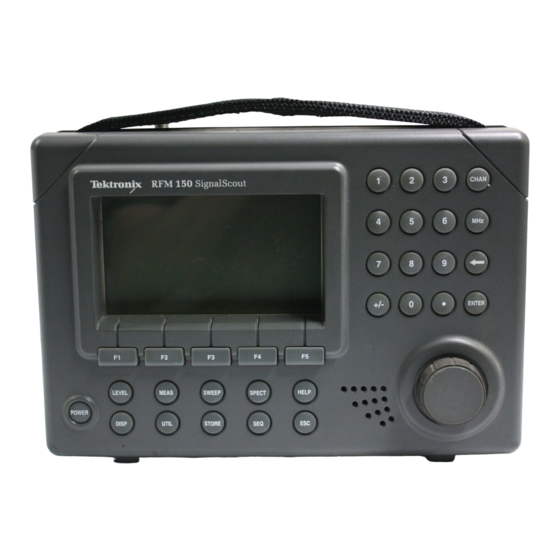
RFM150
SignalScout
Instruction Manual
Firmware Ver. 1.9 and Up
070-9006-04
This document supports firmware version 1.9 and
above.
Warning
The servicing instructions are for use by qualified
personnel only. To avoid personal injury, do not
perform any servicing unless you are qualified to
do so. Refer to the Safety Summary prior to
performing service.
Advertisement
Table of Contents

Related Manuals for Tektronix RFM150


Summary of Contents for Tektronix RFM150
- Page 1 RFM150 SignalScout Instruction Manual Firmware Ver. 1.9 and Up 070-9006-04 This document supports firmware version 1.9 and above. Warning The servicing instructions are for use by qualified personnel only. To avoid personal injury, do not perform any servicing unless you are qualified to do so.
- Page 2 Copyright Tektronix, Inc. All rights reserved. Tektronix products are covered by U.S. and foreign patents, issued and pending. Information in this publication supercedes that in all previously published material. Specifications and price change privileges reserved. Printed in the U.S.A. Tektronix, Inc., P.O. Box 1000, Wilsonville, OR 97070–1000 TEKTRONIX and TEK are registered trademarks of Tektronix, Inc.
- Page 3 Tektronix, with shipping charges prepaid. Tektronix shall pay for the return of the product to Customer if the shipment is to a location within the country in which the Tektronix service center is located. Customer shall be responsible for paying all shipping charges, duties, taxes, and any other charges for products returned to any other locations.
-
Page 5: Table Of Contents
........2–35 RFM150 Instruction Manual... - Page 6 ..... 6–9 Replacing the Back Board Circuit Board Assembly ..6–11 RFM150 Instruction Manual...
- Page 7 ........C–1 RFM150 Instruction Manual...
- Page 8 ....... . . C–16 Sequence Measurements ......C–18 Index RFM150 Instruction Manual...
- Page 9 ......... 2–36 RFM150 Instruction Manual...
-
Page 10: Figure 1-1: The Sweep Display
..5–10 Figure 6–1: Separating the instrument into two parts ..6–3 Figure 6–2: Removing the LCD Display module ..6–5 RFM150 Instruction Manual... - Page 11 ........C–17 Figure C–12: Printed report of Sequence measurement . . . C–18 RFM150 Instruction Manual...
- Page 12 ....4–8 Table 4–11: Certification ......4–8 RFM150 Instruction Manual viii...
- Page 13 Table A–12: Custom channel table worksheet ... A–45 Table B–1: Pin assignments for interface port ... B–2 RFM150 Instruction Manual...
- Page 14 Table of Contents RFM150 Instruction Manual...
-
Page 15: General Safety Summary
Danger indicates an injury hazard immediately accessible as you read the marking. Warning indicates an injury hazard not immediately accessible as you read the marking. Caution indicates a hazard to property including the product. Symbols on the Product The following symbols may appear on the product: RFM150 Instruction Manual... - Page 16 This instrument uses a smart charge system, which prolongs battery life. If the operating time from a full charge seems significantly shortened during the warranty period, contact a Tektronix Service Center to have the battery replaced. After the warranty period, the battery may be replaced by qualified service personnel who have read the service instructions in this manual.
- Page 17 Damage to the seals or failure to replace the weather- proofing plugs could allow rain to enter and possibly damage the product. This product is not designed for use in an explosive atmosphere. RFM150 Instruction Manual xiii...
-
Page 18: Service Safety Summary
Opening the RFM 150 case while an RF signal is applied can expose the operator to hazardous voltages. Always disconnect the RF INPUT connector from the RFM 150 before opening the case. To avoid electric shock, do not touch exposed connections. RFM150 Instruction Manual... -
Page 19: Preface
Preface This manual contains operating and service information for the RFM150; information following the Service Safety Warning page is for qualified service technicians only. Operators should be familiar with basic television terms and measurements, and qualified service technicians should have moderate experience repairing analog and logic circuits. -
Page 20: Documentation Conventions
Key names and labels are shown in uppercase letters when instructions are active, but are spelled out in lowercase during general discussions. For example, “Press SEQ,” but “The sequence menu is used to activate measurement routines.” RFM150 Instruction Manual... -
Page 21: Getting Started
Getting Started... -
Page 23: Product Description
5 Channel Mode. This mode simultaneously displays the levels of five channels. Meter Mode. This is a general purpose level measurement mode which you can use for peaking and/or nulling adjustments. The results are displayed on a simulated analog meter. RFM150 Instruction Manual 1–1... -
Page 24: Other Operating Modes
The 24 Hour test is already loaded in the RFM 150. You can load additional test sequences from a PC (using the companion CSS150 software), or from another RFM 150. You can set these test sequences RFM150 Instruction Manual 1–2... -
Page 25: Results Storage / Printing
Option A3: Australian 220 VAC Power Pack (119-4858-00) Option A6: Japan 100 VAC Power Pack (119-4859-00) Rugged Construction The rugged mechanical construction, high-impact material, and internal shock system provide excellent resistance to damage. Weather-tight construction guarantees operation in varying weather RFM150 Instruction Manual 1–3... -
Page 26: Accessories
RS-232-C DC-9 female-female cable assembly (174-3269-00) Precision female-female type F adapter (103-0301-00) The following optional accessories can be ordered for use with the RFM150. Optional Accessories CSS150 software package with CSS150 User Manual (063-2225-00) Adapter, BNC to F Series (103-0310-00) RFM150 Instruction Manual 1–4... -
Page 27: Tutorial
ON or OFF, as desired. It is usually best to turn the backlight on under low lighting conditions. 3. Using the same method as for backlight, change the CONTRAST MODE setting if desired, based on the type of use and operator preference. RFM150 Instruction Manual 1–5... - Page 28 1 channel display (Mode Help), and ends with a description of the preset keys (Function Keys Help). 3. Press ESC to exit the help screen. RFM150 Instruction Manual 1–6...
- Page 29 SPECT has a tunable marker and readout of the marker fre- quency and signal amplitude. SWEEP provides system-referenced sweep measurements, with a peak-to-valley readout between two tunable marker frequencies. SEQ allows execution of automated test sequences. RFM150 Instruction Manual 1–7...
- Page 30 The offset below it represents the probe loss value. You can change the probe loss value and the high and low pilot frequencies through the Measure Setup Menu, which is accessed RFM150 Instruction Manual 1–8...
- Page 31 3. You can set the REF LVL (in the upper left corner of the screen) by pressing F1, then turning the knob. Since the reference level represents the value at the top of the measurement screen, changing it will effectively move the graph vertically with respect to the screen. RFM150 Instruction Manual 1–9...
- Page 32 Press F3, and note that the RBW (resolution bandwidth) toggles between 30 kHz and 300 kHz. d. Press F4 and note that the detector toggles between peak and average. RFM150 Instruction Manual 1–10...
- Page 33 2. Press CHAN. This ensures that the knob is assigned to tune the instrument by channel. It also outlines the channel number (in the RFM150 Instruction Manual 1–11...
- Page 34 ENTER. Repeat until the desired reference name is entered. Numbers can also be entered; just press the desired number(s). To correct a mistake, press the backspace key (left arrow), then enter the RFM150 Instruction Manual 1–12...
- Page 35 5. Use the markers to read amplitude as follows: a. Press F2 until MKR1 is displayed on-screen above the F2 key. This selects MKR1 as the active marker, and assigns the knob to tune the marker frequency. RFM150 Instruction Manual 1–13...
- Page 36 One of the applications for this display is spotting signals which should not be present. 1. Press the front-panel SPECT key to access the spectrum mode display, as shown in Figure 1–2. RFM150 Instruction Manual 1–14...
-
Page 37: Figure 1-2: Spectrum Display With Knob Assigned To Reference Level
Press F1 until REF is selected (the REF label is outlined). b. Turn the knob to adjust the reference level, and note that the reference value readout near the upper left corner of the screen changes. Adjusting the reference level moves the trace RFM150 Instruction Manual 1–15... - Page 38 CSS150 software. 1. Press STORE, then press F3 to select SITE NAME. Check the ACTIVE SITE NAME near the upper left corner of the screen. If this is correct, proceed to step 2. RFM150 Instruction Manual 1–16...
- Page 39 7. Press the STORE key, then press F2 to select RSLTS MENU. Use the knob to select the result of the test you just executed. You can recognize it by the date and time, and because the TYPE will be SEQUENCE. RFM150 Instruction Manual 1–17...
- Page 40 Set the probe loss and power units as follows: a. Press UTIL. The function key labels across the bottom of the screen will indicate the utility menu actions, without changing the measurement portion of the screen. RFM150 Instruction Manual 1–18...
- Page 41 Press UTIL, then press F4 (RS232). Five editable fields will be displayed, with the present setting for each field indicated by an outline cursor. Figure 1–3 shows the RS232 menu with the factory default settings. RFM150 Instruction Manual 1–19...
-
Page 42: Figure 1-3: Rs232 Menu Showing Factory Settings
RS232 menu (in step 5). The RFM 150 will automatically use these printer settings when a print job is active. (If no print job is active, the RFM150 communication mode is determined by the RS232 menu settings.) RFM150 Instruction Manual... -
Page 43: Figure 1-4: Printer Menu Showing Factory Settings
Press F5 (YEAR), then turn the knob until the current year is displayed. A beep will sound if you exceed the range (1994 through 2025). g. Press ESC until you return to the UTIL menu. RFM150 Instruction Manual 1–21... -
Page 44: Figure 1-5: Printout Of 1 Channel Measurement
6. Press F2 (PRINT). You should see a message screen stating that the print job is in process. To stop the print job, press F5 (ABORT). 7. The printed report should resemble Figure 1–5. Figure 1–5: Printout of 1 Channel measurement RFM150 Instruction Manual 1–22... -
Page 45: Operating Basics
Operating Basics... -
Page 47: Functional Overview
NiCad batteries and operation of the instrument with an external AC/DC adapter. If AC power is connected, and the instrument is turned off or in sleep mode, the battery is charging. Use only the Tektronix adapter supplied with this product. RFM150 Instruction Manual 2–1... -
Page 48: Controls And Indicators
3–8. 2. Use the numeric keypad to enter a channel number or frequency value. Terminate such an entry with CHAN, MHz, or ENTER. You can also use the keypad to enter numbers in alphanumeric text strings. RFM150 Instruction Manual 2–2... - Page 49 The following is a general description of menu functions: LEVEL accesses the signal level measurements submenu. In LEVEL mode, the five function keys are assigned to: 1 CHAN, PILOTS, 5 CHAN, ALL CHAN, and METER. RFM150 Instruction Manual 2–3...
- Page 50 AC adapter into the RFM 150 before connecting to the AC power source. 11. POWER turns the instrument power on and off. Important information about instrument power up and the power switch appears on pages 1–5, 1–18, and 3–11. RFM150 Instruction Manual 2–4...
-
Page 51: Menu Hierarchy
EDIT DEL ALL ACTIVE NAME YES/NO YES/NO DISP SPECT BACKLIGHT CONTRAST CONTRAST MODE KNOB KNOB KNOB DETECT Knob or ON/OFF AUTO/MANUAL SPAN 30 kHz / AVG / keypad entry 300 kHz PEAK Figure 2–3: Menu hierarchy RFM150 Instruction Manual 2–5... -
Page 52: Figure 2-3: Menu Hierarchy (Cont.)
SELECT SELECT CHAN CHAN CHAN FIELD Knob or keypad entry CLOCK TIME DAY OF MONTH YEAR WEEK RS232 BAUD PARITY FLOW TERM ECHO RATE CNTRL PRINTER BAUD PARITY FLOW RATE CNTRL Figure 2–3: Menu hierarchy (Cont.) RFM150 Instruction Manual 2–6... -
Page 53: Figure 2-3: Menu Hierarchy (Cont.)
TEMP ENTRY TEMP TEMP UNITS Knob or F / C keypad entry Use knob to select sequence to be acted upon. EXEC START REPEAT TIME TIMES CLONE YES/NO DEL ALL YES/NO Figure 2–3: Menu hierarchy (Cont.) RFM150 Instruction Manual 2–7... -
Page 54: Explanation Of Readouts
Figure 2–4, pressing a function key tunes the instrument to the programmed preset frequency. (Programming the Presets is described on page 3–14.) 7. When a function key is selected, its label is highlighted. When the function keys control the knob assignment, the highlighted RFM150 Instruction Manual 2–8... -
Page 55: Figure 2-4: Display Readouts And Labels
When a remote command for local lock-out is sent to the RFM150, the local lock-out indicator (an outlined L) will appear to the right of the frequency. There will be no action when a front-panel control is used, except for the POWER key. This condition will remain until the remote command is sent to remove the local lock-out. -
Page 56: Tuning
If you tune to a frequency that does not correspond to a channel in the active channel table, the channel readout is replaced with ‘???’ and the secondary measurement is not displayed. RFM150 Instruction Manual 2–10... -
Page 57: Editing Methods
The function keys select the field to edit. In some menus, each field is assigned to a corresponding function key. In other menus, one key is pressed repeatedly to sequence through the fields. The function key labels along the bottom of the screen will guide you. RFM150 Instruction Manual 2–11... -
Page 58: Figure 2-6: Sample Menu Screen Showing Text Editing
As additional letters are entered, they will appear at the cursor. Entering numbers. Use the keypad (ENTER is not used for numbers in text strings). When a field has been correctly entered, select ACCEPT ENTRY. RFM150 Instruction Manual 2–12... - Page 59 Editing Fields With On-Screen Choices Some fields have on-screen choices, with the current setting indicated by an outline cursor. These fields are edited by turning the knob to the left or right until the desired setting is outlined. RFM150 Instruction Manual 2–13...
- Page 60 Functional Overview RFM150 Instruction Manual 2–14...
-
Page 61: Making Measurements
If a key has no action in that mode, it will not be listed in the table. The measurement discussions are organized in alphabetical order by measurement name. RFM150 Instruction Manual 2–15... -
Page 62: Channel Mode
Tuning. The signal being measured is determined by instrument tuning. Use the knob, numeric keypad, or presets to tune by channel or frequency. (Refer to Tuning on page 2–10.) The tuned channel number and frequency appear on the top line of the display. RFM150 Instruction Manual 2–16... -
Page 63: Figure 2–7: The 1 Channel Mode (Analog Channel)
(channel table editing) and loading channel tables into the RFM 150. To measure a digital channel, proceed as follows. 1. Use the CSS150 software to create a custom channel table with the following information: RFM150 Instruction Manual 2–17... - Page 64 User Action Visual Freq (MHz) Enter the measurement frequency (the frequency at the center of the modulation envelope) RFM150 Channel Type Select DIGITAL C/N Bandwidth (MHz) Enter the symbol rate in mega-symbols per sec. ). (Refer to your encoder/modulator equipment documentation for this information.)
-
Page 65: Figure 2–8: The 1 Channel Mode (Digital Channel)
(for example, pressing STORE to store a measurement result). Press ESC to exit the other menu and restore the 1 channel mode function keys. To change to another level measurement mode, press LEVEL. RFM150 Instruction Manual 2–19... -
Page 66: Pilots Mode
Table 2–3: Functions of active keys in pilots mode Action Menu keys Enters selected menu. (Aborts a partial keypad entry.) HELP Displays context-sensitive help screen; aborts a partial keypad entry. Aborts a partial keypad entry without changing the instrument setup. RFM150 Instruction Manual 2–20... - Page 67 (for example, pressing STORE to store a measurement result). Press ESC to exit the other menu and restore the pilots mode function keys. To change to another level measure- ment mode, press the corresponding function key. RFM150 Instruction Manual 2–21...
-
Page 68: Channel Mode
The function keys and tuning are inactive in this mode. Table 2–4 defines the key actions. Table 2–4: Functions of active keys in 5 channel mode Action Menu keys Enters selected menu. HELP Displays context-sensitive help screen. RFM150 Instruction Manual 2–22... - Page 69 Reference level. This is the level at the top of the screen, and is displayed in the upper left corner of the screen (REF LVL). The RFM150 automatically selects the optimum reference level, based on the five channel level measurements.
-
Page 70: All Channel Mode
Level MKR1 reading Outline indicates knob is assigned Difference between level at marker 1 to control reference level. and level at marker 2 Figure 2–11: The all channel mode display Table 2–5 defines the key actions. RFM150 Instruction Manual 2–24... -
Page 71: Table 2-5: Functions Of Active Keys In All Channel Mode
The companion CSS150 software can be used to create a custom channel table that does not contain unused frequencies. After making this custom channel table active, screen utilization will be significantly improved for most systems. RFM150 Instruction Manual 2–25... - Page 72 To change to another level measurement mode, press LEVEL. If 1 channel or meter mode is entered following all channel mode, the instrument will be tuned to the same frequency as the active marker. RFM150 Instruction Manual 2–26...
-
Page 73: Meter Mode
Pressing backspace during a keypad entry erases the character preceding the cursor. Backspacing 1 click after field is empty aborts partial entry. HELP Displays context-sensitive help screen; aborts a partial keypad entry. Aborts a partial keypad entry without changing the instrument setup. RFM150 Instruction Manual 2–27... -
Page 74: Figure 2-12: The Meter Mode Display
Reference level. Press F1 to assign the knob to REF (the label should be outlined). Use the knob to set the reference level so that the level readout (dark line) is within the central area of the meter scale, not off either end of the scale. RFM150 Instruction Manual 2–28... - Page 75 (for example, pressing STORE to store a measurement result). Press ESC to exit the other menu and restore the meter mode function keys. To change to another level measure- ment mode, press LEVEL. RFM150 Instruction Manual 2–29...
-
Page 76: Carrier-To-Noise Ratio
If the noise at the RFM 150 input is so low that the noise proximity correction can no longer be accurately applied, then a “>” will precede the C/N readout. RFM150 Instruction Manual 2–30... -
Page 77: Figure 2-13: The Carrier-To-Noise Measurement Screen (Analog Channel)
2–17. A sample digital channel measurement is shown in Figure 2–14. The top measurement is the average signal power, and the bottom measurement is the ratio of desired to undesired signal. RFM150 Instruction Manual 2–31... -
Page 78: Figure 2-14: The Carrier-To-Noise Measurement Screen (Digital Channel)
(for example, pressing STORE to store a measurement result). Press ESC to exit the other menu and restore the C/N mode function keys. To change to the hum or FM deviation menus, press MEAS again. RFM150 Instruction Manual 2–32... -
Page 79: Hum
Tunes instrument according to entry mode. Overrides partial keypad entry. Numeric keypad Keying either channel or frequency, followed by CHAN, MHz, or ENTER, tunes the instrument – if chan. or freq. is in the active channel table. RFM150 Instruction Manual 2–33... - Page 80 (for example, pressing STORE to store a measurement result). Press ESC to exit the other menu and restore the C/N mode function keys. To change to the C/N or FM deviation menus, press MEAS again. RFM150 Instruction Manual 2–34...
-
Page 81: Fm Deviation
HUM, C/N, and FM DEV. Select FM DEV. The FM deviation measurement screen, illustrated in Figure 2–16, will be displayed. The top line of the display shows the channel number and frequency of the channel being measured, along with the instrument RFM150 Instruction Manual 2–35... -
Page 82: Figure 2-16: The Fm Deviation Measurement Mode Display
(for example, pressing STORE to store a measurement result). Press ESC to exit the other menu and restore the C/N mode function keys. To change to the C/N or hum menus, press MEAS again. RFM150 Instruction Manual 2–36... -
Page 83: Executing Sequences
Displayed on this screen are the current site name and temperature values with which stored measurement results will be tagged. If these values are not correct, go to the STORE menu and enter the correct values now. RFM150 Instruction Manual 2–37... -
Page 84: Figure 2–18: Execute Sequence Menu
VIEW. To archive using the CSS 150 software and a computer, refer to the CSS150 SignalScout Software User Manual. Exit. To exit the menu or submenu, including the viewed result, one level at a time, press ESC. RFM150 Instruction Manual 2–38... -
Page 85: Spectrum Mode
Overrides partial keypad entry. Numeric keypad Keying either channel or frequency, followed by CHAN, MHz, or ENTER, tunes the instrument – if chan. or freq. is in the active channel table. RFM150 Instruction Manual 2–39... - Page 86 Reference level. The REF level is the level at the top of the screen. The present setting is displayed in the upper left corner of the screen. It can be changed by selecting KNOB REF and turning the knob. Detection. Pressing F5 toggles between peak and average detection. RFM150 Instruction Manual 2–40...
- Page 87 Digital Channel. You can use the Spectrum mode to view a digital signal graphically. To measure the average power of a digital channel, use the 1 Channel mode. (Refer to the instructions on page 2–17). RFM150 Instruction Manual 2–41...
-
Page 88: Sweep Mode
Tunes the active marker or changes the center level. Overrides partial keypad entry. Numeric keypad Keying either channel or frequency, followed by CHAN, MHz, or ENTER, tunes the instrument – if the chan. or freq. is in the active channel table. RFM150 Instruction Manual 2–42... - Page 89 Entering other frequencies will cause an error message, leaving the marker frequency unchanged. The inactive marker is the boundary for tuning the active marker; the active marker cannot cross the inactive marker. RFM150 Instruction Manual 2–43...
-
Page 90: Figure 2–21: The Sweep Lvl/Ref Submenu Display
Store a sweep reference. The results of ‘all channel’ measurements are used for the sweep references. For example, you can store an all channel mode record at the head end, and use it as a reference for field measurements. RFM150 Instruction Manual 2–44... -
Page 91: Figure 2–22: Reference Menu
Now the sweep menu is displayed, and the reference that you have just selected will appear as the active reference in the upper left corner of the screen. Exit. Press ESC to exit the menu or submenus, one level at a time. RFM150 Instruction Manual 2–45... - Page 92 Making Measurements RFM150 Instruction Manual 2–46...
-
Page 93: Reference
Reference... -
Page 95: Channel Tables
Editing Channel Tables To edit channel tables, press the front-panel UTIL key, then select CHAN TABLE. A list of all channel tables that are loaded in the instrument will appear (Figure 3–1). RFM150 Instruction Manual 3–1... -
Page 96: Figure 3–1: Channel Tables Menu
Figure 3–2: Editing channel tables RFM150 Instruction Manual 3–2... -
Page 97: Table 3-1: Channel Table Fields For Editing
Allows tracking of which RFM 150 channels are scrambled. Amplitude Offset –12.5 to +12.5 CSS150 or Value added to absolute RFM 150 visual carrier level measure- ments. Usually used to cor- rect for scrambled channel levels. RFM150 Instruction Manual 3–3... - Page 98 Only custom channel tables can be deleted. If you attempt to delete a fixed channel table, an error message will be displayed and the table will not be deleted. Stored measurement results are dependent on the channel table that was active when they were stored. When you RFM150 Instruction Manual 3–4...
- Page 99 UTIL, then select CHAN TABLE. Use the knob if needed to scroll. To edit or delete the table, select EDIT CHAN or DEL. Exit. Press ESC to exit the menu, one level at a time. RFM150 Instruction Manual 3–5...
-
Page 100: Clock
DAY OF WEEK: SUN MON TUE WED Cursor arrow FRI SAT indicates selected Outline indicates field. DAY–MONTH: 23–AUG selected field. YEAR: 1994 YEAR HOUR MINUTE DAY OF DAY– Function keys select WEEK MONTH field to be edited. Figure 3–3: The Clock menu RFM150 Instruction Manual 3–6... -
Page 101: Clone Configuration
Probe loss Reference for all channels, meter, and spectrum modes Resolution bandwidth (RBW) for meter and spectrum modes Screen contrast level Screen contrast mode (manual/auto) Span for spectrum mode Speaker volume in meter mode Temperature units RFM150 Instruction Manual 3–7... -
Page 102: Display Adjustment
The manual mode is used by selecting CONTRAST, then using either the knob or keypad to select a contrast value between 0% and 100%. If the instrument is set to auto mode when a contrast value is selected, it will automatically switch to manual mode. RFM150 Instruction Manual 3–8... -
Page 103: Help
Turning off the instrument power will also exit the help screen. In the upper right of every Mode Help screen is a battery charge indicator. This is the percent of charge remaining in the battery, with 100% indicating a full charge. RFM150 Instruction Manual 3–9... - Page 104 (F1 through F5). When you are instructed to press a function key, press the ESC key first. Exit. When you are finished with the help screen, press the ESC key to exit. Turning off the instrument power will also exit the help screen. RFM150 Instruction Manual 3–10...
-
Page 105: Power Mode
If the instrument is in a sleep state, pressing POWER will provide a query screen. The query screen (shown in Figure 3–4) identifies the sequence and its scheduled start time, and provides an opportunity to abort the sequence. RFM150 Instruction Manual 3–11... -
Page 106: Figure 3–4: The Sleep State Query Screen
Figure 3–4: The sleep state query screen After performing a scheduled measurement sequence, the instrument will either power down or return to the sleep state to wait for the next sequence. RFM150 Instruction Manual 3–12... -
Page 107: Power Up / Power Down Modes
Press F1 or F2 to select the field, then turn the knob to change the setting. The outline cursor moves to the new setting. Exit. Press ESC to exit the menu, one level at a time. The new settings will be saved. RFM150 Instruction Manual 3–13... -
Page 108: Powering Up From An Ac Source
You can also set the preset to auto, allowing its preset channel and frequency to be programmed by the press-and-hold method. When auto is used, the on-screen labels will be controlled by the RFM 150. RFM150 Instruction Manual 3–14... -
Page 109: Figure 3–6: Assign Preset Menu
TOP LABEL (the top line of the on-screen label), BOTTOM LABEL (the bottom line of the label), or FREQ (frequency to which the preset will tune the instrument). Edit the fields as desired, using the standard editing techniques. Refer to Editing Methods on page 2–11. RFM150 Instruction Manual 3–15... -
Page 110: Figure 3–7: Editing Preset F1
3. When the preset is programmed, the on-screen channel / frequency label will change automatically. If you release the key in under 3 seconds, it will not be programmed; it will tune the instrument as usual. RFM150 Instruction Manual 3–16... -
Page 111: Printing Stored Measurement Results
Appendix C. Auto Power Down Auto power down will not occur while a direct print job is in process. If enabled, auto power down will occur after 10 minutes of no instrument activity, including printing. RFM150 Instruction Manual 3–17... - Page 112 If the RFM 150 is not connected to a printer when PRINT or PRINT ALL is selected, and CTS/RTS handshaking is selected, the instrument will display the print message. To clear this message, select ABORT PRINT and YES. RFM150 Instruction Manual 3–18...
-
Page 113: Probe Loss
Using the knob. The knob changes the value in increments of 0.1 dB. A knob entry is not cancelled by pressing ESC. Exit. When edit is complete, press ESC to exit the menu, one level at a time. RFM150 Instruction Manual 3–19... -
Page 114: Sequences (Adding And Deleting)
SEQ. The sequence is sent to the destination RFM 150 and placed at the end of the list of sequences. To display this list on the destination monitor, press SEQ. Use the knob to scroll if needed. RFM150 Instruction Manual 3–20... - Page 115 Select DEL. A confirmation screen will appear; select YES to delete all sequences. Selecting NO or ESC will cancel the request. Exit. Press ESC to exit the menu, one level at a time. RFM150 Instruction Manual 3–21...
-
Page 116: Site Name
20 characters. New site names are added to the end of the list of site names. The number of site names that can be stored is limited only by the amount of available non-volatile memory. RFM150 Instruction Manual 3–22... - Page 117 Exit. Press ESC to exit the menu, one level at a time. RFM150 Instruction Manual 3–23...
-
Page 118: Stored Measurement Results
CSS150 software. Stored measurement results can also be sent directly from the RFM150 to a printer. Store a measurement result. After making a measurement, press STORE, then select STORE RSLT. This stores the most recent measurement result from the current measurement mode. -
Page 119: Figure 3–11: Additional Information Screen For 5 Channel Measurement Type
Press F2 (PRINT) to print the selected measurement result. While the result is printing, a print in progress message is displayed, as shown in Figure 3–12. To stop the print job, press ABORT PRINT and select YES. General reference information about printing appears on page 3–17. RFM150 Instruction Manual 3–25... -
Page 120: Figure 3–12: The Print In Progress Message
Select YES to delete. To cancel the request without deleting any records, select NO or press ESC. When a result is deleted, the list is automatically compacted and the records are renumbered. RFM150 Instruction Manual 3–26... -
Page 121: Temperature
ENTER. A partial keypad entry can be aborted by pressing ESC or by backspacing one click after the field is empty. Exit. When editing is complete, press ESC to exit the menu, one level at a time. The new settings will be saved. RFM150 Instruction Manual 3–27... -
Page 122: Units
Turning the knob back and forth toggles the setting between dBmV and dBuV. Exit. After editing the level units as desired, press ESC to exit the menu, one level at a time. The new setting will be saved. RFM150 Instruction Manual 3–28... -
Page 123: Specifications
Specifications... - Page 125 Required Equipment list on page 5–3. Installation Requirements This is a portable unit, and has no special installation requirements. RFM150 Instruction Manual 4–1...
-
Page 126: Table 4-1: Input Signal Requirements
10 dB over 300 MHz plus 1 dB for each additional 100 MHz up to 17 dB total. For input signals > 50 dBmV and > 500 MHz, the input must be disconnected during self calibration. RFM150 Instruction Manual 4–2... - Page 127 For channel video bandwidths greater than 4 MHz, carrier-to-noise range is decreased by 10 log (video bandwidth / 4 MHz). For system B/G, with the lower adjacent channel carrying NICAM, C/N measurement accuracy guaranteed for out-of-service measurements only. RFM150 Instruction Manual 4–3...
-
Page 128: Table 4-3: Measurement Repeatability
In-channel response must not vary by more than 0.5 dB. Measurement accuracy guaranteed from 10 to 50 C. Accuracy for deviations less than 12 kHz is typical. RFM150 Instruction Manual 4–4... -
Page 129: Table 4-4: Spectral Display Mode
Use precision F-style connector. To meet measurement accuracy specifications, the system visual carrier amplitude variation must be less than 10 dB over 300 MHz plus 1 dB for each additional 100 MHz up to 17 dB total. RFM150 Instruction Manual 4–5... -
Page 130: Table 4-6: Dc Jack Input
REQ: 3.5 hours REF: Backlight off, typical use Non-Operating REQ: 6 months Sleep State REQ: 36 hours REF: No connection to the Interface Port Charge Time REQ: 8 hours REF: Battery temp. between +10 and +45 C RFM150 Instruction Manual 4–6... -
Page 131: Table 4-9: Environmental Characteristics
Altitude (Operating) REQ: 15,000 feet (4572 meters) Altitude (Non-operating) REQ: 50,000 feet (15240 meters) Humidity REQ: Meets Tektronix Class 3 (062-2853-00) 5% to 95% over 0 to + 50 C Shock (Operating) REQ: Meets Tektronix Class 3 (062-2853-00) REF: Three drops on each face of 50 G, 11 m duration, half-sine pulse shape. -
Page 132: Table 4-10: Physical Characteristics
Specifications Table 4–9: Environmental characteristics (Cont.) Name Description Shock and Vibration REQ: Meets Tektronix 062-2858-00 (Non-operating) Repetitive Shock Test (Loose Load Vibration): Platform vibration frequency adjusted until package repeatedly leaves the platform about 1/8 in or until acceleration of platform is 1.1 G. - Page 133 CAT II Local-level mains (wall sockets). Equipment at this level includes appliances, portable tools, and similar products. Equipment is usually cord-connected CAT I Secondary (signal level) or battery operated circuits of electronic equipment RFM150 Instruction Manual 4–9...
- Page 134 Specifications RFM150 Instruction Manual 4–10...
- Page 135 WARNING The following servicing instructions are for use only by qualified personnel. To avoid injury, do not perform any servicing other than that stated in the operating instructions unless you are qualified to do so. Refer to all Safety Summaries before performing any service.
-
Page 137: Performance Check
Performance Check... - Page 139 5 dB, 10 dB, and first 20 dB attenuator steps IF1GAIN adjustment IF3GAIN adjustment Log Detector Resolution BW Filter Insertion Loss Lin Detector FM Detector Reference Oscillator Correction Other Instrument Functions Checked Battery Operation External Power Operation Communications Port Front Panel Operation RFM150 Instruction Manual 5–1...
- Page 140 12 kHz of deviation input Verify FM deviation measurement 25 kHz 4.5 kHz accuracy with 25 kHz of deviation input IF filter amplitude calibration Change between 30 kHz and 300 kHz. BW is 1 dB or less. RFM150 Instruction Manual 5–2...
-
Page 141: Required Equipment
AM Modulation (internal or external): Amplitude range 0 to 2.5% (corresponds to 0 to 5% RFM 150 reading). Rate 50, 60, 100 or 120 Hz. Example: Hewlett-Packard 8657A Signal Generator with a Tektronix CFG250 Function Generator The function generator is used when testing hum accuracy, to drive the external modulation input to generate the 50, 60, 100, or 120 Hz AM modulation rate. -
Page 142: Signal Characterization
1. Connect the test equipment as shown in Figure 5–1, 5–2, or 5–3. Power meter RF signal source with 50 output impedance 50 to 75 minimum loss pad sensor 5.7 dB loss) head coaxial cable Figure 5–1: Hookup for 50 source output RFM150 Instruction Manual 5–4... - Page 143 If your power meter does not display amplitude in dBmV, add +48.7 to the reading in dBm to convert to dBmV. 4. Repeat steps 2 and 3 for frequencies of 110, 210, 310, 410, 510, 610, 710, 810, 910 and 1000 MHz. RFM150 Instruction Manual 5–5...
-
Page 144: Performance Check Procedure
4. Use the following key sequence to select the 1 channel measurement mode: [LEVEL] [F1]. 5. Verify amplitude accuracy a. Use the following key sequence to tune the RFM 150 to 10 MHz: [1] [0] [MHz]. RFM150 Instruction Manual 5–6... - Page 145 Verify that the displayed hum reading is 5 1%. Record the RFM150 reading in your copy of Table 5–1. NOTE. The RFM 150 Hum reading is the ratio of peak-to-peak AM modulation to carrier level, per the NCTA standard. The displayed result will be twice the percent modulation setting on the generator.
-
Page 146: Front Panel / Backlight / Clock Operation Check
[MEAS] [F3]. c. Verify that the reading is 12 kHz 3.2 kHz. Record the RFM150 reading in your copy of Table 5–1. d. Increase the FM deviation of the input signal to 25 kHz. e. Verify that the reading is 25 kHz 4.5 kHz. Record the RFM150 reading in your copy of Table 5–1. -
Page 147: Figure 5–4: Level Menu Function Key Assignments
If the clock is incorrect, you can reset it after completing this procedure. See page 3–6 for instructions. 14. Press [SWEEP] to enter the Sweep mode. Check that the word “SWEEP” appears in the upper right corner of the screen. RFM150 Instruction Manual 5–9... -
Page 148: Figure 5–7: Store Menu Function Key Assignments
With the last site name still selected, press [F4] to delete it. A query screen will appear. Press [F1] to confirm. Check that the site name (A1234567890) has been removed from the list. RFM150 Instruction Manual 5–10... -
Page 149: Communications Port Function Check
(outline) the baud rate setting of 9600. Use this method to configure the RFM 150 communications port as follows: BAUD RATE 9600 PARITY NONE FLOW CONTROL XON/XOFF TERMINATOR CRLF ECHO b. Check that the parameters on your computer or terminal match those given above. RFM150 Instruction Manual 5–11... - Page 150 RFM 150 screen, indicating that the instrument is in the remote operating mode. 24. Connect the RS-232 cable from the RFM150 to a serial printer. 25. Press [UTIL] to enter the Utility menu, then press [F5] to select the Printer menu.
-
Page 151: Maintenance
Maintenance... -
Page 153: Replacement Procedures
CAUTION. The only service that you should perform during the warranty period is battery replacement. For board replacement during the warranty period, return the instrument to a Tektronix Service Center. When installing new circuit boards, or returning boards to Tektronix for exchange, be sure to use a clean, static-free work area, and follow anti-static handling methods. - Page 154 6. Disconnect the ribbon cable from the Back Board circuit board assembly. 7. Proceed to the instructions for replacing the desired module. RFM150 Instruction Manual 6–2...
-
Page 155: Figure 6–1: Separating The Instrument Into Two Parts
Replacement Procedures Check gasket Front part of instrument Rubber gasket RF connector Back part of instrument Figure 6–1: Separating the instrument into two parts RFM150 Instruction Manual 6–3... -
Page 156: Replacing The Calibrated Board Set
For questions regarding board exchange, contact your local Tektronix office, or call the Tektronix Beaverton Service Depot at 1-800-835-9433. 1. Perform Instrument Disassembly on page 6–1. This includes turning off the instrument and making sure there is no connection to AC power, RF input, or interface port. -
Page 157: Figure 6–2: Removing The Lcd Display Module
10. Perform Instrument Assembly on page 6–15. 11. Complete the Performance Check, beginning on page 5–1. 12. Return the exchange board set, using the packaging in which you received the replacement board set. RFM150 Instruction Manual 6–5... -
Page 158: Replacing The Front Panel Circuit Board Assembly, Speaker
Remove the spacer, if installed. b. Using a 9/16 in wrench, remove the nut and two washers from the encoder. c. Working from the inside of the front panel, lift out the encoder. Inspect the gasket and replace if necessary. RFM150 Instruction Manual 6–6... -
Page 159: Inside
Place the large knob spacer (if available) on the post, then replace the large knob. (If the spacer is not available, while installing the knob, hold it slightly above the instrument to prevent it from binding.) Tighten the set screw. RFM150 Instruction Manual 6–7... - Page 160 12. Perform Instrument Assembly on page 6–15. 13. Perform the following steps from the Performance Check, beginning on page 5–6: Step 1, Step 2, and Steps 9 through 20. RFM150 Instruction Manual 6–8...
-
Page 161: Replacing The Lcd Display Module
6. Position the replacement LCD Display module on the board set, inserting the pins into the Processor/Power Supply circuit board assembly. Install the four screws that secure the LCD Display module and tighten to 4 in-lbs. RFM150 Instruction Manual 6–9... -
Page 162: Figure 6–4: Removing The Lcd Display Module
9. Perform Instrument Assembly on page 6–15. 10. Perform the following steps from the Performance Check, beginning on page 5–6: Step 1, Step 2, and Steps 9 through 20. RFM150 Instruction Manual 6–10... -
Page 163: Replacing The Back Board Circuit Board Assembly
7. Partially install the two screws that attach the Back Board circuit board assembly to the instrument, but do not tighten. 8. Install and tighten the two screws on the communication port. 9. Tighten the two screws on the Back Board circuit board assembly to 4 in-lbs. RFM150 Instruction Manual 6–11... -
Page 164: Figure 6–5: Removing The Back Board Circuit Board Assembly
Check that the clip is locked on the pins. 11. Perform Instrument Assembly on page 6–15. 12. Perform the following steps from the Performance Check, beginning on page 5–6: Step 1, Step 2, and Steps 21 through 23. RFM150 Instruction Manual 6–12... -
Page 165: Replacing The Battery
Be sure that the battery lead is installed as shown in Figure 6–5, so that it will not be pinched during instrument assembly. Check that the clip is locked on the pins. CAUTION. A damaged battery lead can cause serious equipment damage. RFM150 Instruction Manual 6–13... - Page 166 7. Replace the battery cover, ensuring that the battery lead is not caught between the housing and the cover. Install and tighten the four screws. 8. Perform Instrument Assembly on page 6–15. 9. Perform the Performance Check on page 5–6. RFM150 Instruction Manual 6–14...
-
Page 167: Instrument Assembly
Processor/Power Supply circuit board assembly is extended so that it can be attached to the Back Board circuit board assembly in a later step. d. Align the Calibrated Board Set with the eight posts in the instrument front casing. RFM150 Instruction Manual 6–15... -
Page 168: Figure 6–6: Positioning The Ribbon Cable
4. Connect the ribbon cable from J10 on the Processor/Power Supply circuit board assembly to J500 on the Back Board circuit board assembly. 5. Slip the instrument carrying strap over the two posts on the back cover of the instrument. RFM150 Instruction Manual 6–16... -
Page 169: Figure 6–7: Installing The Rf Connector
8. Install the ten screws on the rear cover and tighten to 8 in-lbs. 9. If you are using an RF adapter, install it on the RF connector with the 7/16 in wrench. Tighten to 15 in-lbs. 10. This completes Instrument Assembly. RFM150 Instruction Manual 6–17... - Page 170 Replacement Procedures RFM150 Instruction Manual 6–18...
-
Page 171: Recharging The Battery
AC adapter into the RFM 150 before connecting to the AC power source. 1. Connect the supplied Tektronix AC adapter to the RFM 150 power input. Connect the adapter plug to an appropriate AC power source. The instrument will emit two short beeps, and the screen will remain blank. - Page 172 Recharging the Battery RFM150 Instruction Manual 6–20...
-
Page 173: Cleaning The Instrument
Do not use abrasive cleaners. 2. Clean the LCD display with a soft, lint-free cloth dampened in non-abrasive glass cleaner. Do not use tissue or paper products. Do not use abrasive cleaners. RFM150 Instruction Manual 6–21... -
Page 174: Interior Cleaning
Cleaning of rosin residue is not recommended for this product. Most cleaning solvents tend to reactivate the rosin and spread it under components where it may cause corrosion under humid conditions. The rosin residue, if left alone, does not exhibit these corrosive properties. RFM150 Instruction Manual 6–22... - Page 175 Hardened dirt or grease can be removed with a cotton swab dampened with isopropyl alcohol. Do not use abrasive cleaners. Do not clean rosin residue. 5. Clean the LCD display with a soft, lint-free cloth dampened with non-abrasive glass cleaner. RFM150 Instruction Manual 6–23...
- Page 176 WARNING. Do not assemble, apply power, or apply RF signal input to the instrument until the interior is thoroughly dry. 6. Allow the interior to dry thoroughly. 7. Perform Instrument Assembly on page 6–15. 8. Perform the Performance Check on page 5–6. RFM150 Instruction Manual 6–24...
-
Page 177: Replaceable Electrical Parts
Replaceable Electrical Parts... -
Page 179: Parts Ordering Information
Replaceable Electrical Parts This section contains a list of the components that are replaceable for the RFM150. Use this list to identify and order replacement parts. Parts Ordering Information Replacement parts are available through your local Tektronix field office or representative. -
Page 180: Using The Replaceable Parts List
Use the U.S. Federal Catalog handbook H6-1 for further item name identification. Mfr. Code This indicates the code of the actual manufacturer of the part. Mfr. Part Number This indicates the actual manufacturer’s or vendor’s part number. RFM150 Instruction Manual 7–2... - Page 181 Abbreviations conform to American National Standard ANSI Y1.1–1972. Mfr. Code to Manufacturer Cross Index The table titled Manufacturers Cross Index shows codes, names, and addresses of manufacturers or vendors of components listed in the parts list. RFM150 Instruction Manual 7–3...
- Page 182 Replaceable Electrical Parts RFM 150 Instruction Manual 7–4...
- Page 183 Replaceable Electrical Parts 7–5 RFM 150 Instruction Manual...
- Page 184 Replaceable Electrical Parts RFM 150 Instruction Manual 7–6...
-
Page 185: Replaceable Mechanical Parts
Replaceable Mechanical Parts... -
Page 187: Parts Ordering Information
Replaceable Mechanical Parts This section contains a list of the components that are replaceable for the RFM150. Use this list to identify and order replacement parts. Parts Ordering Information Replacement parts are available through your local Tektronix field office or representative. -
Page 188: Using The Replaceable Parts List
Use the U.S. Federal Catalog handbook H6-1 for further item name identification. Mfr. Code This indicates the code of the actual manufacturer of the part. Mfr. Part Number This indicates the actual manufacturer’s or vendor’s part number. RFM150 Instruction Manual 8–2... - Page 189 Abbreviations conform to American National Standard ANSI Y1.1–1972. Mfr. Code to Manufacturer Cross Index The table titled Manufacturers Cross Index shows codes, names, and addresses of manufacturers or vendors of components listed in the parts list. RFM150 Instruction Manual 8–3...
- Page 190 Replaceable Mechanical Parts RFM 150 Instruction Manual 8–4...
- Page 191 Replaceable Mechanical Parts 8–5 RFM 150 Instruction Manual...
- Page 192 Replaceable Mechanical Parts RFM 150 Instruction Manual 8–6...
- Page 193 Replaceable Mechanical Parts 8–7 RFM 150 Instruction Manual...
- Page 194 Replaceable Mechanical Parts RFM 150 Instruction Manual 8–8...
- Page 195 Replaceable Mechanical Parts 8–9 RFM 150 Instruction Manual...
- Page 196 Replaceable Mechanical Parts Figure 8–1: Exploded view of the RFM 150 RFM150 Instruction Manual 8–10...
-
Page 197: Appendices
Appendices... -
Page 199: Appendix A: Channel Tables
This includes the defaults for the four editable fields. Blanks are provided to fill in new values when the fields are edited. A blank table appears at the end of the section, to allow for custom channel tables. RFM150 Instruction Manual A–1... - Page 200 Appendix A: Channel Tables RFM150 Instruction Manual A–2...
-
Page 201: Table A–1: Catv–Standard
151.25 NTSC –1.25 157.25 NTSC –1.25 163.25 NTSC –1.25 169.25 NTSC –1.25 175.25 NTSC –1.25 181.25 NTSC –1.25 187.25 NTSC –1.25 193.25 NTSC –1.25 199.25 NTSC –1.25 205.25 NTSC –1.25 211.25 NTSC –1.25 217.25 NTSC –1.25 RFM150 Instruction Manual A–3... - Page 202 355.25 NTSC –1.25 361.25 NTSC –1.25 367.25 NTSC –1.25 373.25 NTSC –1.25 379.25 NTSC –1.25 385.25 NTSC –1.25 391.25 NTSC –1.25 397.25 NTSC –1.25 403.25 NTSC –1.25 409.25 NTSC –1.25 415.25 NTSC –1.25 421.25 NTSC –1.25 RFM150 Instruction Manual A–4...
- Page 203 559.25 NTSC –1.25 565.25 NTSC –1.25 571.25 NTSC –1.25 577.25 NTSC –1.25 583.25 NTSC –1.25 589.25 NTSC –1.25 595.25 NTSC –1.25 601.25 NTSC –1.25 607.25 NTSC –1.25 613.25 NTSC –1.25 619.25 NTSC –1.25 625.25 NTSC –1.25 RFM150 Instruction Manual A–5...
- Page 204 763.25 NTSC –1.25 769.25 NTSC –1.25 775.25 NTSC –1.25 781.25 NTSC –1.25 787.25 NTSC –1.25 793.25 NTSC –1.25 799.25 NTSC –1.25 805.25 NTSC –1.25 811.25 NTSC –1.25 817.25 NTSC –1.25 823.25 NTSC –1.25 829.25 NTSC –1.25 RFM150 Instruction Manual A–6...
- Page 205 967.25 NTSC –1.25 973.25 NTSC –1.25 979.25 NTSC –1.25 985.25 NTSC –1.25 991.25 NTSC –1.25 997.25 NTSC –1.25 1003.25 NTSC –1.25 1009.25 NTSC –1.25 1015.25 NTSC –1.25 1021.25 NTSC –1.25 1027.25 NTSC –1.25 1033.25 NTSC –1.25 RFM150 Instruction Manual A–7...
- Page 206 CATV–Standard channel table Channel Frequency Channel Channel Skip Scrambled Dwell Amplitude Time Offset Number (MHz) Type Edge (MHz) 1039.25 NTSC –1.25 1045.25 NTSC –1.25 1051.25 NTSC –1.25 1057.25 NTSC –1.25 1063.25 NTSC –1.25 1069.25 NTSC –1.25 RFM150 Instruction Manual A–8...
-
Page 207: Table A–2: Catv–500 Channel Table
133.25 NTSC –1.25 139.25 NTSC –1.25 145.25 NTSC –1.25 151.25 NTSC –1.25 157.25 NTSC –1.25 163.25 NTSC –1.25 169.25 NTSC –1.25 175.25 NTSC –1.25 181.25 NTSC –1.25 187.25 NTSC –1.25 193.25 NTSC –1.25 199.25 NTSC –1.25 RFM150 Instruction Manual A–9... - Page 208 337.25 NTSC –1.25 343.25 NTSC –1.25 349.25 NTSC –1.25 355.25 NTSC –1.25 361.25 NTSC –1.25 367.25 NTSC –1.25 373.25 NTSC –1.25 379.25 NTSC –1.25 385.25 NTSC –1.25 391.25 NTSC –1.25 397.25 NTSC –1.25 403.25 NTSC –1.25 RFM150 Instruction Manual A–10...
- Page 209 445.25 NTSC –1.25 451.25 NTSC –1.25 457.25 NTSC –1.25 463.25 NTSC –1.25 469.25 NTSC –1.25 475.25 NTSC –1.25 481.25 NTSC –1.25 487.25 NTSC –1.25 493.25 NTSC –1.25 499.25 NTSC –1.25 505.25 NTSC –1.25 511.25 NTSC –1.25 RFM150 Instruction Manual A–11...
- Page 210 Appendix A: Channel Tables RFM150 Instruction Manual A–12...
-
Page 211: Table A–3: Broadcast Channel Table
477.25 NTSC –1.25 483.25 NTSC –1.25 489.25 NTSC –1.25 495.25 NTSC –1.25 501.25 NTSC –1.25 507.25 NTSC –1.25 513.25 NTSC –1.25 519.25 NTSC –1.25 525.25 NTSC –1.25 531.25 NTSC –1.25 537.25 NTSC –1.25 543.25 NTSC –1.25 RFM150 Instruction Manual A–13... - Page 212 681.25 NTSC –1.25 687.25 NTSC –1.25 693.25 NTSC –1.25 699.25 NTSC –1.25 705.25 NTSC –1.25 711.25 NTSC –1.25 717.25 NTSC –1.25 723.25 NTSC –1.25 729.25 NTSC –1.25 735.25 NTSC –1.25 741.25 NTSC –1.25 747.25 NTSC –1.25 RFM150 Instruction Manual A–14...
- Page 213 819.25 NTSC –1.25 825.25 NTSC –1.25 831.25 NTSC –1.25 837.25 NTSC –1.25 843.25 NTSC –1.25 849.25 NTSC –1.25 855.25 NTSC –1.25 861.25 NTSC –1.25 867.25 NTSC –1.25 873.25 NTSC –1.25 879.25 NTSC –1.25 885.25 NTSC –1.25 RFM150 Instruction Manual A–15...
- Page 214 Appendix A: Channel Tables RFM150 Instruction Manual A–16...
-
Page 215: Table A–4: Catv–Hrc Channel Table
138.01 NTSC –1.25 144.01 NTSC –1.25 150.01 NTSC –1.25 156.01 NTSC –1.25 162.01 NTSC –1.25 168.01 NTSC –1.25 174.01 NTSC –1.25 180.01 NTSC –1.25 186.01 NTSC –1.25 192.01 NTSC –1.25 198.01 NTSC –1.25 204.01 NTSC –1.25 RFM150 Instruction Manual A–17... - Page 216 342.02 NTSC –1.25 348.02 NTSC –1.25 354.02 NTSC –1.25 360.02 NTSC –1.25 366.02 NTSC –1.25 372.02 NTSC –1.25 378.02 NTSC –1.25 384.02 NTSC –1.25 390.02 NTSC –1.25 396.02 NTSC –1.25 402.02 NTSC –1.25 408.02 NTSC –1.25 RFM150 Instruction Manual A–18...
- Page 217 546.03 NTSC –1.25 552.03 NTSC –1.25 558.03 NTSC –1.25 564.03 NTSC –1.25 570.03 NTSC –1.25 576.03 NTSC –1.25 582.03 NTSC –1.25 588.03 NTSC –1.25 594.03 NTSC –1.25 600.03 NTSC –1.25 606.03 NTSC –1.25 612.03 NTSC –1.25 RFM150 Instruction Manual A–19...
- Page 218 Appendix A: Channel Tables CATV–HRC channel table Channel Frequency Channel Channel Skip Scrambled Dwell Amplitude Time Offset Number (MHz) Type Edge (MHz) 618.03 NTSC –1.25 624.03 NTSC –1.25 630.03 NTSC –1.25 636.03 NTSC –1.25 642.03 NTSC –1.25 RFM150 Instruction Manual A–20...
-
Page 219: Table A–5: Catv–Irc Channel Table
145.25 NTSC –1.25 151.25 NTSC –1.25 157.25 NTSC –1.25 163.25 NTSC –1.25 169.25 NTSC –1.25 175.25 NTSC –1.25 181.25 NTSC –1.25 187.25 NTSC –1.25 193.25 NTSC –1.25 199.25 NTSC –1.25 205.25 NTSC –1.25 211.25 NTSC –1.25 RFM150 Instruction Manual A–21... - Page 220 349.25 NTSC –1.25 355.25 NTSC –1.25 361.25 NTSC –1.25 367.25 NTSC –1.25 373.25 NTSC –1.25 379.25 NTSC –1.25 385.25 NTSC –1.25 391.25 NTSC –1.25 397.25 NTSC –1.25 403.25 NTSC –1.25 409.25 NTSC –1.25 415.25 NTSC –1.25 RFM150 Instruction Manual A–22...
- Page 221 553.25 NTSC –1.25 559.25 NTSC –1.25 565.25 NTSC –1.25 571.25 NTSC –1.25 577.25 NTSC –1.25 583.25 NTSC –1.25 589.25 NTSC –1.25 595.25 NTSC –1.25 601.25 NTSC –1.25 607.25 NTSC –1.25 613.25 NTSC –1.25 619.25 NTSC –1.25 RFM150 Instruction Manual A–23...
- Page 222 Appendix A: Channel Tables CATV–IRC channel table Channel Frequency Channel Channel Skip Scrambled Dwell Amplitude Time Offset Number (MHz) Type Edge (MHz) 625.25 NTSC –1.25 631.25 NTSC –1.25 637.25 NTSC –1.25 643.25 NTSC –1.25 RFM150 Instruction Manual A–24...
-
Page 223: Table A–6: China–Dk Channel Table
136.25 –1.25 144.25 –1.25 152.25 –1.25 160.25 –1.25 168.25 –1.25 176.25 –1.25 184.25 –1.25 192.25 –1.25 200.25 –1.25 208.25 –1.25 216.25 –1.25 224.25 –1.25 232.25 –1.25 240.25 –1.25 248.25 –1.25 256.25 –1.25 264.25 –1.25 272.25 –1.25 RFM150 Instruction Manual A–25... - Page 224 304.25 –1.25 312.25 –1.25 320.25 –1.25 328.25 –1.25 336.25 –1.25 344.25 –1.25 352.25 –1.25 360.25 –1.25 368.25 –1.25 376.25 –1.25 384.25 –1.25 392.25 –1.25 400.25 –1.25 408.25 –1.25 416.25 –1.25 424.25 –1.25 432.25 –1.25 440.25 –1.25 RFM150 Instruction Manual A–26...
-
Page 225: Table A–7: Europe–Bg Channel Table
140.25 –1.25 147.25 –1.25 154.25 –1.25 161.25 –1.25 168.25 –1.25 175.25 –1.25 182.25 –1.25 189.25 –1.25 196.25 –1.25 203.25 –1.25 210.25 –1.25 217.25 –1.25 224.25 –1.25 231.25 –1.25 238.25 –1.25 245.25 –1.25 252.25 –1.25 259.25 –1.25 RFM150 Instruction Manual A–27... - Page 226 559.25 –1.25 567.25 –1.25 575.25 –1.25 583.25 –1.25 591.25 –1.25 599.25 –1.25 607.25 –1.25 615.25 –1.25 623.25 –1.25 631.25 –1.25 639.25 –1.25 647.25 –1.25 655.25 –1.25 663.25 –1.25 671.25 –1.25 679.25 –1.25 687.25 –1.25 695.25 –1.25 RFM150 Instruction Manual A–28...
- Page 227 711.25 –1.25 719.25 –1.25 727.25 –1.25 735.25 –1.25 743.25 –1.25 751.25 –1.25 759.25 –1.25 767.25 –1.25 775.25 –1.25 783.25 –1.25 791.25 –1.25 799.25 –1.25 807.25 –1.25 815.25 –1.25 823.25 –1.25 831.25 –1.25 839.25 –1.25 847.25 –1..25 RFM150 Instruction Manual A–29...
- Page 228 Appendix A: Channel Tables RFM150 Instruction Manual A–30...
-
Page 229: Table A–8: Europe–Dk Channel Table
135.25 –1.25 143.25 –1.25 151.25 –1.25 159.25 –1.25 167.25 –1.25 175.25 –1.25 183.25 –1.25 191.25 –1.25 199.25 –1.25 207.25 –1.25 215.25 –1.25 223.25 –1.25 231.25 –1.25 239.25 –1.25 247.25 –1.25 255.25 –1.25 263.25 –1.25 271.25 –1.25 RFM150 Instruction Manual A–31... - Page 230 407.25 –1.25 415.25 –1.25 423.25 –1.25 431.25 –1.25 439.25 –1.25 447.25 –1.25 455.25 –1.25 463.25 –1.25 471.25 –1.25 479.25 –1.25 487.25 –1.25 495.25 –1.25 503.25 –1.25 511.25 –1.25 519.25 –1.25 527.25 –1.25 535.25 –1.25 543.25 –1.25 RFM150 Instruction Manual A–32...
- Page 231 679.25 –1.25 687.25 –1.25 695.25 –1.25 703.25 –1.25 711.25 –1.25 719.25 –1.25 727.25 –1.25 735.25 –1.25 743.25 –1.25 751.25 –1.25 759.25 –1.25 767.25 –1.25 775.25 –1.25 783.25 –1.25 791.25 –1.25 799.25 –1.25 807.25 –1.25 815.25 –1.25 RFM150 Instruction Manual A–33...
- Page 232 Appendix A: Channel Tables Europe–DK channel table Channel Frequency Channel Channel Skip Scrambled Dwell Amplitude Time Offset Number (MHz) Type Edge (MHz) 823.25 –1.25 831.25 –1.25 839.25 –1.25 847.25 –1.25 855.25 –1.25 RFM150 Instruction Manual A–34...
-
Page 233: Table A–9: Europe–I Channel Table
535.25 –1.25 543.25 –1.25 551.25 –1.25 559.25 –1.25 567.25 –1.25 575.25 –1.25 583.25 –1.25 591.25 –1.25 599.25 –1.25 607.25 –1.25 615.25 –1.25 623.25 –1.25 631.25 –1.25 639.25 –1.25 647.25 –1.25 655.25 –1.25 663.25 –1.25 671.25 –1.25 RFM150 Instruction Manual A–35... - Page 234 711.25 –1.25 719.25 –1.25 727.25 –1.25 735.25 –1.25 743.25 –1.25 751.25 –1.25 759.25 –1.25 767.25 –1.25 775.25 –1.25 783.25 –1.25 791.25 –1.25 799.25 –1.25 807.25 –1.25 815.25 –1.25 823.25 –1.25 831.25 –1.25 839.25 –1.25 847.25 –1.25 RFM150 Instruction Manual A–36...
-
Page 235: Table A–10: France–L Channel Table
240.00 SECAM –1.25 248.00 DIGITAL –1.25 256.00 DIGITAL –1.25 264.00 DIGITAL –1.25 272.00 DIGITAL –1.25 280.00 DIGITAL –1.25 288.00 DIGITAL –1.25 303.00 DIGITAL –1.25 315.00 DIGITAL –1.25 327.00 DIGITAL –1.25 339.00 SECAM –1.25 351.00 SECAM –1.25 RFM150 Instruction Manual A–37... - Page 236 607.25 SECAM –1.25 615.25 SECAM –1.25 623.25 SECAM –1.25 631.25 SECAM –1.25 639.25 SECAM –1.25 647.25 SECAM –1.25 655.25 SECAM –1.25 663.25 SECAM –1.25 671.25 SECAM –1.25 679.25 SECAM –1.25 687.25 SECAM –1.25 695.25 SECAM –1.25 RFM150 Instruction Manual A–38...
- Page 237 767.25 SECAM –1.25 775.25 SECAM –1.25 783.25 SECAM –1.25 791.25 SECAM –1.25 799.25 SECAM –1.25 807.25 SECAM –1.25 815.25 SECAM –1.25 823.25 SECAM –1.25 831.25 SECAM –1.25 839.25 SECAM –1.25 847.25 SECAM –1.25 855.25 SECAM –1.25 RFM150 Instruction Manual A–39...
- Page 238 Appendix A: Channel Tables RFM150 Instruction Manual A–40...
-
Page 239: Table A–11: Japan–M Channel Table
489.25 NTSC –1.25 495.25 NTSC –1.25 501.25 NTSC –1.25 507.25 NTSC –1.25 513.25 NTSC –1.25 519.25 NTSC –1.25 525.25 NTSC –1.25 531.25 NTSC –1.25 537.25 NTSC –1.25 543.25 NTSC –1.25 549.25 NTSC –1.25 555.25 NTSC –1.25 RFM150 Instruction Manual A–41... - Page 240 687.25 NTSC –1.25 693.25 NTSC –1.25 699.25 NTSC –1.25 705.25 NTSC –1.25 711.25 NTSC –1.25 717.25 NTSC –1.25 723.25 NTSC –1.25 729.25 NTSC –1.25 735.25 NTSC –1.25 741.25 NTSC –1.25 747.25 NTSC –1.25 753.25 NTSC –1.25 RFM150 Instruction Manual A–42...
- Page 241 Appendix A: Channel Tables Japan–M Channel Table Channel Frequency Channel Channel Skip Scrambled Dwell Amplitude Time Offset Number (MHz) Type Edge (MHz) 759.25 NTSC –1.25 765.25 NTSC –1.25 RFM150 Instruction Manual A–43...
- Page 242 Appendix A: Channel Tables RFM150 Instruction Manual A–44...
-
Page 243: Table A–12: Custom Channel Table Worksheet
Table A–12: Custom channel table worksheet Skip: Scrambled: Dwell Time: Amplitude Offset: Aural Offset: Second Aural Offset: C/N Bandwidth: Custom Channel Table _________________________________________________________ Skip Scrambled Dwell Amplitude Channel Frequency Channel Channel Time Offset Number (MHz) Type Edge (MHz) RFM150 Instruction Manual A–45... - Page 244 Appendix A: Channel Tables Custom Channel Table _________________________________________________________ Channel Frequency Channel Channel Skip Scrambled Dwell Amplitude Time Offset Number (MHz) Type Edge (MHz) RFM150 Instruction Manual A–46...
-
Page 245: Appendix B: Remote Communications
RFM 150. The RFM 150 can communicate with another RFM 150, a printer, or a computer. Communicating with Another RFM150 Before communication can occur between two instruments, they must be configured and connected as follows: 1. -
Page 246: Figure B–1: Rs232 Menu Showing Factory Settings
Table B–1: Pin assignments for interface port Pin Number Signal Name RS-232C Name Not connected RX (Receive Data) TX (Transmit Data) DTR (Data Terminal Ready) GND (Signal Ground) DSR (Data Set Ready) RTS (Request to Send) CTS (Clear to Send) Reserved RFM150 Instruction Manual B–2... -
Page 247: Figure B–2: Top View Of Rfm 150, Showing The Interface Port
Channel Tables (refer to page 3–1), Sequences (refer to page 3–20), and Clone Configuration (refer to page 3–20). Enlarged view of connector Interface port with weather-resistant cover closed Figure B–2: Top view of RFM 150, showing the interface port RFM150 Instruction Manual B–3... -
Page 248: Communicating With A Computer (Using The Css150
Download measurement results to a computer for archival or use with another application, such as a spreadsheet Print stored measurement results NOTE. Pilot and 5 channel measurements will not be downloaded. The hookup and operational instructions are in the CSS150 Sig- nalScout Software User Manual. RFM150 Instruction Manual B–4... -
Page 249: Communicating With A Printer
Figure B–4. 3. Press any function key to select the corresponding field for edit, then turn the knob to the left or right to change the setting to match your printer. RFM150 Instruction Manual B–5... -
Page 250: Figure B–4: Rs232 Menu Showing Factory Settings
Table B–1, and the connector location is shown in Figure B–2. Printing Stored Results Instructions for printing stored results are given in the Tutorial on page 1–22. More information about the print function appears in the Reference section, on pages 3–17 and 3–25. RFM150 Instruction Manual B–6... -
Page 251: Appendix C: Printed Report Formats
“???”. If you have not entered a site name, the site name field will be left blank. Measurement Information Measurement information follows the header. To view this information on screen, press STORE, then select RSLTS MENU and VIEW. RFM150 Instruction Manual C–1... - Page 252 When graphics are involved, the printed report will display the measurement information in a textual format. Under certain conditions, an error or over range condition may occur while making a measurement. The print report replaces the measurement value with the text “ERR” or “OVER”. RFM150 Instruction Manual C–2...
-
Page 253: Channel Measurement
1. Channel number and frequency 2. Channel type (in this case, DIGITAL) 3. Digital level and its measurement units 4. Probe loss offset 5. Digital carrier amplitude offset indicator (optional asterisk after digital level) 6. Normalization bandwidth RFM150 Instruction Manual C–3... - Page 254 Appendix C: Printed Report Formats Figure C–1: Printed report of 1 Channel measurement (single aural analog channel) RFM150 Instruction Manual C–4...
-
Page 255: Pilots Measurement
1. Low and high pilot channel numbers and frequencies 2. Low and high pilot measured levels 3. Pilot level amplitude offset indicator (optional asterisk after level) 4. Low/high pilot delta amplitude 5. Probe loss offset Figure C–2: Printed report of Pilots measurement RFM150 Instruction Manual C–5... -
Page 256: Channel Measurement
1. Channel numbers and frequencies of all five measurements 2. Measured levels of all five measurements 3. Level amplitude offset indicator (optional asterisk after each level) 4. Probe loss offset Figure C–3: Printed report of 5 Channel measurement RFM150 Instruction Manual C–6... -
Page 257: Meter Measurement
The report contains the following information: 1. Measurement frequency 2. Measured level 3. Level amplitude offset indicator (optional asterisk after level) 4. Reference level 5. Probe loss offset 6. Measurement resolution bandwidth Figure C–4: Printed report of Meter measurement RFM150 Instruction Manual C–7... -
Page 258: All Channel Measurement
The number of All Channel measurements in the report is dependent on the channel table. Note that skipped channels are not listed. If a marker is on a skipped channel, the marker level and delta marker amplitude fields will be blank. RFM150 Instruction Manual C–8... -
Page 259: Figure C–5: Partial Printed Report Of All Channel Measurement
Appendix C: Printed Report Formats Figure C–5: Partial printed report of All Channel measurement RFM150 Instruction Manual C–9... -
Page 260: Carrier-To-Noise Measurement
3. Digital level and its measurement units 4. Digital carrier amplitude offset indicator (optional asterisk after visual level) 5. Noise near noise indicator (optional “>” before C/N value) 6. Probe loss offset 7. C/N value 8. Normalization bandwidth RFM150 Instruction Manual C–10... -
Page 261: Figure C–6: Printed Report Of Carrier-To-Noise Measurement
Appendix C: Printed Report Formats Figure C–6: Printed report of Carrier-to-Noise measurement RFM150 Instruction Manual C–11... -
Page 262: Hum Measurement
2. Channel type (in this case, NTSC, PAL, or SECAM) 3. Visual level and its measurement units 4. Visual carrier amplitude offset indicator (optional asterisk after visual level) 5. Probe loss offset 6. Measured hum Figure C–7: Printed report of Hum measurement RFM150 Instruction Manual C–12... -
Page 263: Fm Deviation Measurement
2. Channel type (in this case, NTSC, PAL, or SECAM) 3. Visual level and its measurement units 4. Visual carrier amplitude offset indicator (optional asterisk after visual level) 5. Probe loss offset 6. Measured FM deviation Figure C–8: Printed report of FM Deviation measurement RFM150 Instruction Manual C–13... -
Page 264: Off-Channel Stored Measurement
A sample Off-Channel measurement print report is shown in Figure C–9. The report contains the following information: 1. Channel noted as unknown 2. Measurement frequency 3. Measured level and its measurement units 4. Probe loss offset Figure C–9: Printed report of Off-Channel measurement RFM150 Instruction Manual C–14... -
Page 265: Spectrum Measurement
4. Span (in MHz or kHz units) 5. Resolution bandwidth (in kHz units) 6. Probe loss offset (for all measurements) 7. Frequency and amplitude level of each individual spectrum measurement Figure C–10: Partial printed report of Spectrum measurement RFM150 Instruction Manual C–15... -
Page 266: Sweep Measurement
6. Marker measured level amplitude offset indicator (optional asterisk after level) for each marker 7. Probe loss offset (for all measurements) 8. Channel number and frequency of each individual sweep measurement 9. Delta amplitude level of each individual sweep measurement RFM150 Instruction Manual C–16... -
Page 267: Figure C–11: Partial Printed Report Of Sweep Measurement
Appendix C: Printed Report Formats Figure C–11: Partial printed report of Sweep measurement RFM150 Instruction Manual C–17... -
Page 268: Sequence Measurements
The header line displays the sequence repetition number. A sample Sequence measurement print report is shown in Figure C–12. Figure C–12: Printed report of Sequence measurement RFM150 Instruction Manual C–18... - Page 269 Index...
- Page 271 Asterisk (*), 2–8 Center frequency, 1–16, 2–40 Audio, 2–3, 2–27 Center level readout (CENTER Aural carriers, 2–29 LVL), 2–44 Auto power down, 1–18, 1–21, Center the trace (CENTER 3–13 TRACE), 1–13, 2–44 Auto presets, 2–23, 3–16 RFM150 Instruction Manual Index–1...
- Page 272 Erase a character, 2–3, 2–12 ESC key, 2–4 EXEC, 1–17 Date, 1–21 Executing sequences, 1–16, 1–17 Date setting (DAY OF WEEK, Executing sequences (EXEC), DAY–MONTH), 3–6 2–37 dBmV, 3–28 dBuV, 3–28 Delete channel tables, 3–4 F keys, 2–3 sequences, 3–21 RFM150 Instruction Manual Index–2...
- Page 273 Measurement repeatability, 4–4 Interrupting a sequence, 2–38 Measurement sequences, 2–37 Memory upgrade, 1–3 Menu keys, 2–3 Menu tree, 2–5 Meter mode, 1–10, 2–27 Keypad, 2–2, 2–10 MHz key, 2–2 Keypad replacement, 6–6 Minimum span, 2–40 Knob, 2–3, 2–10 RFM150 Instruction Manual Index–3...
- Page 274 Press-and-hold programming, 3–16 the keypads, 6–6 PRINT, 3–25 the LCD Display mode, 6–9 Print the speaker, 6–6 error message, 3–18 Replacing the battery, 6–13 hookup, B–6 Replacing the Calibrated Board interface configuration, 1–20, Set, 6–4 B–5 RFM150 Instruction Manual Index–4...
- Page 275 Time, 1–21, 3–6 Span/division (SPAN), 1–14 Tuning, 2–10 Speaker, 2–3, 2–27 Two-carrier sound channels, 2–17 Speaker replacement, 6–6 Specifications, 4–2 SPECT key, 2–4 Spectral display specifications, 4–5 Units, 3–28 Spectrum mode (SPECT), 1–14, UTIL key, 2–4 2–39 RFM150 Instruction Manual Index–5...
- Page 276 Index View measurement result (VIEW), Year setting (YEAR), 3–6 2–38, 3–24 Volume, 2–3 RFM150 Instruction Manual Index–6...
Need help?
Do you have a question about the RFM150 and is the answer not in the manual?
Questions and answers