Sign In
Upload
Manuals
Brands
Tektronix Manuals
Measuring Instruments
RSA3408
Tektronix RSA3408 Manuals
Manuals and User Guides for Tektronix RSA3408. We have
1
Tektronix RSA3408 manual available for free PDF download: Service Manual
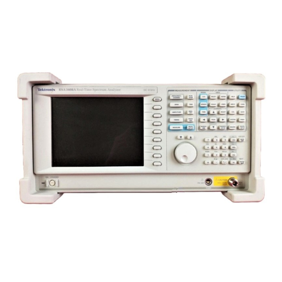
Tektronix RSA3408 Service Manual (236 pages)
8 GHz Real-Time Spectrum Analyzer
Brand:
Tektronix
| Category:
Measuring Instruments
| Size: 6 MB
Table of Contents
List of Figures
7
Table of Contents
7
Figure 3- 1: Spectrum of the Calibration Signal (100 Mhz, - 20 Dbm)
31
Figure 3- 2: Setup Display
32
Table 3- 1: Span and RBW
32
Figure 3- 3: Reference Level Setting and Overrange Indicator
33
Figure 3- 4: Spectrogram Display
33
Figure 3- 5: Diagnostic Screen
34
Table 3- 2: Internal Diagnostic Program
34
Table 3- 3: Test Equipment
36
Figure 3- 6: Auto Test Initial Screen
38
Table 3- 4: Test Item Selection
39
Figure 3- 7: Performance Test Result Display
42
Table 3- 5: Procedure for Failed Test Item
45
Figure 3- 8: Hookup for Calibrating the Power Sensor
55
Figure 3- 9: Hookup for Setting the Signal Generator Output
55
Table 3- 6: Level Linearity Test Result
65
Table 3- 7: Spurious Measurement
77
Table 4- 1: Test Equipment
84
Figure 4- 1: Hookup for Storing the Cal Factors in the Power Meter
87
Figure 4- 2: Initial Test Hookup
89
Figure 4- 3: Hookup for Calibrating the Power Sensor
91
Figure 4- 4: Initial Test Hookup
92
Figure 4- 5: Hookup for Calibrating the Power Sensor
94
Table 4- 2: Compatibility of the Spurious Correction File
97
Figure 4- 6: UNCAL Display
98
Figure 4- 7: Calibration Menu
99
Figure 4- 8: Center Offset
100
Figure 4- 9: DC Offset
101
Figure 4- 10: Auto Calibration Initial Screen
102
Table 4- 3: Calibration Items
103
Figure 4- 11: Test Hookup
116
Figure 4- 12: Test Hookup
117
Table 5- 1: Relative Susceptibility to Static-Discharge Damage
121
Table 5- 2: External Inspection Check List
123
Table 5- 3: Internal Inspection Check List
124
Table 5- 4: Summary of Procedures
127
Table 5- 5: Tools Required for Module Removal
128
Figure 5- 1: Analyzer Orientation
129
Figure 5- 2: External Modules
130
Figure 5- 3: RF Modules
131
Figure 5- 4: CPU Board and Disk Modules
132
Figure 5- 5: Removable Hard Disk Modules (Option 06)
133
Figure 5- 6: Motherboard and Daughterboards
134
Figure 5- 7: Bottom Modules - Power Supply
135
Figure 5- 8: Bottom Modules - RF1
136
Figure 5- 9: Front Panel Modules
137
Figure 5- 10: Chassis Modules
138
Access Procedure
139
Figure 5- 11: Guide to Removal Procedures
139
Is Line Cord P.5
140
Procedures for External Modules
140
Figure 5- 12: Line Cord and Cabinet Removal
141
Front Cushion P.5
141
2? Cabinet Modules P.5
142
Is RF2 Module
145
Procedures for RF Modules
145
RF3 Module P.5
145
RF4 Module P.5
146
3? RF5 Module P.5
148
No RF6 Module P.5
148
A62 Front Connection Board P.5
149
CPU Board P.5
149
Floppy Disk Drive P.5
149
Hard Disk Drive P.5
149
Fan
150
Table 5- 6: Normal Supply Voltages
195
Table 5- 7: Test Point Voltages on A70
196
Table 5- 8: Symptoms and Faulty Modules
197
Advertisement
Advertisement
Related Products
Tektronix RSA3408B
Tektronix RSA3408A
Tektronix RSA306
Tektronix RSA3303A
Tektronix RSA3303B
Tektronix RSA3308B
Tektronix RSA306B
Tektronix RSA3UP-03
Tektronix RSA306B-SMA
Tektronix RSA3300A
Tektronix Categories
Test Equipment
Measuring Instruments
Amplifier
Portable Generator
Printer
More Tektronix Manuals
Login
Sign In
OR
Sign in with Facebook
Sign in with Google
Upload manual
Upload from disk
Upload from URL