Sign In
Upload
Manuals
Brands
Tektronix Manuals
Control Unit
80E05
Tektronix 80E05 Manuals
Manuals and User Guides for Tektronix 80E05. We have
1
Tektronix 80E05 manual available for free PDF download: User Manual
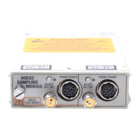
Tektronix 80E05 User Manual (68 pages)
Electrical Sampling Modules
Brand:
Tektronix
| Category:
Control Unit
| Size: 0 MB
Table of Contents
Table of Contents
5
General Safety Summary
7
Environmental Considerations
9
Preface
11
Manual Structure
11
Related Documentation
11
Getting Started
13
Table 1: Application Software Version Required
13
Product Description
14
Table 2: Sampling Module Features
14
Figure 1: Sampling Module Block Diagram
15
Figure 2: Sampling Module, 80E04 Shown
15
Options and Accessories
16
Options
16
Standard Accessories
16
Optional Accessories
16
Table 3: Standard Accessories
16
Table 4: Optional Accessories
16
Installation
18
Electrostatic Discharge
18
Figure 3: Sampling Module Compartments
18
Static Controlled Workstation
19
Module Installation
20
Figure 4: Installing a Sampling Module
20
Compensation
21
Operating Basics
23
Usage
23
Front-Panel Controls
24
Signal Connector
24
Channel Selection
24
Figure 5: Sampling Module, 80E04 Shown
24
TEKPROBE Connector
25
TDR on Indicator
25
System Interaction
25
Commands from the Main Instrument Front Panel
25
Programmer Interface Commands
26
User Adjustments
26
Cleaning
26
Figure 6: Vertical Setup Dialog Box
26
Reference
29
Taking TDR Measurements
29
Figure 7: Simplified Schematic Diagram of Step Generator - Positive Polarity
30
Figure 8: Step Generator with a Shorted Output
31
Figure 9: Step Generation with a 50 Ω Load
31
Figure 10: Step Generation with an Open Circuit
31
Figure 11: TDR Displays for Typical Loads
33
TDR Measurements Background
39
Figure 12: Microstrip Discontinuities
39
Figure 13: TDR Waveform of Microstrip in Figure 12
40
Figure 14: TDR Step and Reflection (Short)
41
Finding the Velocity of Propagation and Locating Mismatches
42
TDR Measurement Units
42
Figure 15: TDR Step and Reflection (50 Ω Line Terminated in 75 Ω)
43
Making Accurate TDR Measurements
44
Taking Differential and Common-Mode TDR Measurements
44
Connector and Adapter Care Requirements
50
Visual Inspection
50
Cleaning Connectors
51
Assembly and Torquing
53
Table 5: Torque Wrench Information
54
TDR Impedance Measuring
55
Detecting Blown Inputs
55
EOS (Electrical Overstress) Prevention
56
Figure 16: TDR Step of Undamaged Sampling Module
56
Figure 17: First Example of EOS Error
57
Figure 18: Second Example of EOS Error Showing Cumulative Effect
58
Specifications
59
Table 6: Electrical Sampling Modules - Descriptions
59
Table 7: Electrical Sampling Modules - Signal Acquisition
60
Table 8: Electrical Sampling Module (80E04) - TDR System
62
Table 9: Electrical Sampling Modules - Timebase System
63
Table 10: Electrical Sampling Modules - Power Consumption
63
Table 11: Electrical Sampling Modules - Mechanical
64
Glossary
65
Index
67
Advertisement
Advertisement
Related Products
Tektronix 80E01
Tektronix 80E02
Tektronix 80E03
Tektronix 80E04
Tektronix 80E06
Tektronix 80E07
Tektronix 80E08
Tektronix 80E09
Tektronix 80E10
Tektronix 80C14
Tektronix Categories
Test Equipment
Measuring Instruments
Amplifier
Portable Generator
Printer
More Tektronix Manuals
Login
Sign In
OR
Sign in with Facebook
Sign in with Google
Upload manual
Upload from disk
Upload from URL