Sign In
Upload
Manuals
Brands
SYNAPTICON Manuals
Servo Drives
SOMANET Circulo 7
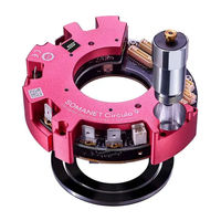
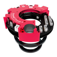
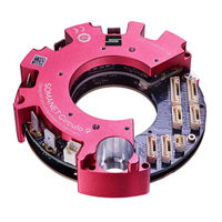
SYNAPTICON SOMANET Circulo 7 Manuals
Manuals and User Guides for SYNAPTICON SOMANET Circulo 7. We have
6
SYNAPTICON SOMANET Circulo 7 manuals available for free PDF download: Documentation, Manual, Hardware Manual, Wiring Instructions, Installation Manual
SYNAPTICON SOMANET Circulo 7 Documentation (1031 pages)
Brand:
SYNAPTICON
| Category:
Servo Drives
| Size: 49 MB
Table of Contents
Method
1
Table of Contents
2
Encoder Port
2
Hardware Manuals
25
Handling Instructions
31
Electrostatic Discharge
31
Magnetic Sensitive Devices
32
SOMANET Circulo
33
Overview
35
Technical Specifications
38
Power Specification
38
General Specification
38
Optional Integrated Encoders
40
Accuracy and Repeatability of the Integrated Encoders
42
Optional Integrated Brake
43
Ordering Information
44
Load Cycle
45
Thermal Mounting Considerations
46
Current as a Function of Mounting Temperature
47
Ambient Air
49
Downloads
50
Documents
50
CAD Files
50
Installation Guide
51
Wiring Instructions
52
Power and Brake
54
Supply and Phases
54
Connecting a Brake
57
Encoders and IO
59
Encoder Overview
59
Analog Input
60
Encoder Ports
61
Digital IO
66
Ethercat / STO-SBC in & out
68
Analog Input Specification
73
Differential
73
Single-Ended
74
Temperature Sensor
75
Specification for the Single-Ended Temperature Sensor Input
77
Battery for Multi-Turn
79
Suitable Batteries
79
Power Consumption of Multi-Turn
80
Ethercat-STO Cable
81
Overview
81
Pinout of the Connectors
82
Instructions for Manufacturing the Cables
84
Maximum Cable Lengths
90
Mating Parts
91
Connector Details and Mating Part Numbers
91
Mechanical Integration
93
Circulo Mounting Example
94
Mounting the Encoder Disc
95
Mounting a Hollow-Shaft Secondary Bearing
96
Routing the Motor Phase Cables
97
Dimensions and Drawings
99
Dimensions
99
Weight and Inertia of the Encoder Rings
103
Drilling Patterns
103
Mounting a Bearing
106
Side View with Phase Connectors
107
Mounting Encoder Rings
109
Axial Distance Tolerances
109
Planar Displacements
111
Encoder Calibration
113
Encoder Accuracy
114
Narrow Angle Errors (Encoder System-Specific Non-Linearity)
115
Wide Angle Error (Installation-Dependent Non-Linearity)
116
Detecting the Encoder Non-Linearity
117
Calibration Procedure
118
Prerequisite
118
Performing the Procedure
118
Troubleshooting
123
Encoder System Diagnostic
125
LED Signals
131
Overview
131
Legend
131
Status LED
132
Firmware
132
Bootloader
133
Ethercat LED
133
Safety Functions (STO-SBC)
134
Safety Specifications
135
System Requirements
135
Technical Specifications
135
Safety Connectors
138
Wiring the Safety Inputs
139
Cabling Lenghts
139
Connection Diagrams for the STO Inputs
139
Manual Switch + Drives
140
Safety PLC PM (Plus-Minus Output) + Drives
140
Safety PLC PP (Plus-Plus Output) + Drives
141
Connection Diagram for the Brake
141
Using the Safety Functions
142
Timing Diagrams
142
Timing Diagram for STO-Function Without Connected Brake
142
Timing Diagram for STO-Function with SBC-Function
143
Truth Table for Digital Inputs
145
Diagnostic Functions
145
Software Diagnostics
145
STO-SBC Status Register
145
Examples for Realising Safety Functions
147
Emergency Stop
148
Stop Category 1 Emergency Stop (Safe Stop 1)
149
Prerequisites
149
Wiring
150
Configuration
150
Verification
151
Prevention of Unexpected Start-Up
152
Commissioning and Maintenance
153
Commissioning
153
Maintenance
153
Changelog of the Safety-Related Documentation
154
SOMANET Node
155
Overview
156
Technical Specifications
157
Power Specifications
157
General Specifications
157
Load Cycle
160
Thermal Mounting Considerations
161
Downloads
163
Documents
163
CAD Files
163
Installation Guide
164
Wiring Instructions
165
Overview of Connectors
165
Power and Brake
166
Pinout Power Terminal
166
Connecting a Brake
169
Encoders and IO
171
Encoder Port
171
Encoder Port 3 / Digital IO
173
Analog in
174
Ethercat Port
178
Connector Details and Mating Parts Numbers
180
Mounting Instructions
181
Heat Dissipation
181
Dimensions
181
Interference with Magnetic Fields
183
On-Site Installation Guide (UL)
184
Branch Fuse Required
184
Field Wiring Terminal Marking
185
Downloads
186
LED Signals
187
Overview
187
Legend
187
Core LED
188
Firmware
188
Bootloader
189
Drive LED
189
Com LED
190
SOMANET Node Safety (Original Instructions)
191
Dimensions
192
Specifications of the Safety Functions
193
System Requirements
193
Technical Specifications
193
Block Diagram
195
Setup of the Safety Functions
196
Connecting the STO/SBC Inputs
197
STO/SBC Input Port
197
Wiring Examples for the STO/SBC Inputs
198
Connection Diagram for the Brake
200
Brake Power Output (STO/SBC)
201
Connector Mating Parts and Cable Lengths
202
Using the Safety Functions
203
Timing Diagrams
203
Timing Diagram for STO-Function Without Connected Brake
203
Timing Diagram for STO-Function with SBC-Function
204
Truth Table for Digital Inputs
206
Diagnostic Functions
206
Fault Diagnostics
206
Fault Reaction
206
Resetting Diagnostic Faults
207
STO-SBC Status Register
207
Examples for Realising Safety Functions
209
Prevention of Unexpected Start-Up
209
Stop Category 0 (STO)
209
Stop Category 1 (SS1)
210
Prerequisites
210
Wiring
211
Configuration
211
Verification
212
Commissioning and Maintenance
213
Commissioning
213
Maintenance
213
Changelog of the Safety-Related Documentation
214
SOMANET Accessories
215
SOMANET Braking Chopper 48V 500W
216
Overview
216
Technical Specs
217
Installing the Module and Setting the Threshold Voltage
218
Connecting the Board to DC-BUS
219
Suitable Cables
219
Wiring
219
Failsafe Behavior
220
Multi-Board Option
220
Led
221
Dimensions
222
Sin/Cos Encoder Cable Adapter
223
Overview
223
Block Diagram
223
Connectors
224
Encoder Connector Top
224
Encoder Connector Bottom
225
Interface Connector
225
Mounting Remarks
226
Strain Relief
227
Soldered Cables
227
Industrial I/O Cable Adapter
228
Overview
228
Block Diagram
228
Pinouts
230
Connector Details and Mating Parts
230
Strain Relief
231
Soldered Cables
232
Attaching the Adapter
232
Abi/Biss Encoder Cable Adapter
233
Overview
233
Block Diagram
233
Connectors
234
Encoder Connector Top
234
Encoder Connector Bottom
235
Interface Connector
235
Mounting Remarks
236
Strain Relief
237
Soldered Cables
237
Downloads
237
Samples & Legacy Products
238
Circulo Sample
241
Technical Specifications
243
Power Specification
243
General Specification
243
Optional Integrated Encoders
244
Accuracy and Repeatability of the Encoder Rings
246
Optional Integrated Brake
247
Installation Guide
248
Wiring Instructions
249
Overview of Connectors
249
Power Supply and Motor Brake
250
Encoders and IO
254
Temperature Sensor
261
Mating Parts and Encoder Battery
262
Dimensions and Mechanical Mounting
265
Dimensions
265
Drilling Patterns for Mounting
268
Heat Dissipation
271
Mounting Encoder Rings
272
Aligning the Encoder Discs
272
Mounting Tolerances
275
Encoder Accuracy
277
Wide Angle Error (Long Wave Error, Integral Nonlinearity)
278
Narrow Angle Error (Short Wave Error, Differential Nonlinearity, Sub Divisional Error)
278
LED Signals
279
Overview
279
Legend
279
Core LED
280
Firmware
280
Bootloader
281
Drive LED
281
Ethercat LED
282
Safety Functions (STO-SBC)
283
Safety Specifications
284
System Requirements
284
Technical Specifications
284
Block Diagram
286
Wiring the Safety Inputs
287
Connection Diagrams for the STO Inputs
287
Connection Diagrams for the STO/SBC Feedback Output
292
Connection Diagram for the Brake
294
Using the Safety Functions
295
Timing Diagrams
295
Truth Table for Digital Inputs
297
Diagnostic Functions
297
STO-SBC Status Register
298
Use Cases
299
Commissioning and Maintenance
300
Commissioning
300
Maintenance
300
Circulo Sample
301
Technical Specifications
304
Power Specification
304
General Specification
305
Optional Integrated Encoders
306
Accuracy and Repeatability of the Integrated Encoders
308
Optional Integrated Brake
310
Ordering Information
310
Installation Guide
312
Wiring Instructions
313
Power and Brake
315
Encoders and IO
321
Temperature Sensor
335
Ethercat-STO Cable
337
Mating Parts
346
Dimensions and Mechanical Mounting
348
Dimensions
348
Drilling Patterns for Mounting
351
Heat Dissipation
354
Mounting Encoder Rings
355
Aligning the Encoder Discs
355
Mounting Tolerances
357
Battery for Multi-Turn
358
Mounting a Bearing
360
Encoder Accuracy
362
Wide Angle Error (Long Wave Error, Integral Nonlinearity)
363
Narrow Angle Error (Short Wave Error, Differential Nonlinearity, Sub Divisional Error)
363
Encoder Calibration
364
Overview
364
Prerequisite
365
Encoder System Diagnostic
365
Calibration Procedure
367
LED Signals
369
Overview
369
Legend
369
Status LED
370
Firmware
370
Bootloader
371
Ethercat LED
371
Safety Functions (STO-SBC)
372
Safety Specifications
373
System Requirements
373
Technical Specifications
373
Safety Connectors
376
Wiring the Safety Inputs
377
Cabling Lenghts
377
Connection Diagrams for the STO Inputs
377
Connection Diagram for the Brake
379
Using the Safety Functions
381
Timing Diagrams
381
Truth Table for Digital Inputs
383
Diagnostic Functions
383
STO-SBC Status Register
384
Examples for Realising Safety Functions
385
Emergency Stop
386
Stop Category 1 Emergency Stop (Safe Stop 1)
387
Prevention of Unexpected Start-Up
390
Commissioning and Maintenance
391
Commissioning
391
Maintenance
391
Changelog of the Safety-Related Documentation
392
SOMANET Node Rev
393
Technical Specifications
394
Power Specifications
394
General Specifications
394
Hardware Diagrams
396
Ethercat Module
396
Processor Module
397
Drive Module
398
Installation Guide
399
Downloads
399
Wiring Instructions
400
Warning about Using Contactors Behind the Power Supply
400
Connectors
402
Power Terminal
402
Encoder Port
403
Encoder Port 3 / Digital IO
405
Analog in
406
Ethercat Port
407
Connector Types and Mating Parts Numbers
409
Grounding and Connecting a Brake
410
Connecting a Brake
410
Mounting Instructions
412
Heat Dissipation
412
Dimensions
412
Interference with Magnetic Fields
413
LED Signals
415
Overview
415
Legend
415
Core LED
416
Firmware
416
Bootloader
417
SOMANET Node Rev
418
Technical Specifications
419
Power Specifications
419
General Specifications
420
Hardware Diagrams
422
Ethercat Module
422
Processor Module
423
Drive Module
424
Installation Guide
425
Wiring Instructions
426
Warning about Using Contactors Behind the Power Supply
426
Connectors
428
Ethercat IN/OUT
428
Power Terminal
429
Encoder Port
430
Encoder Port 3 / Digital IO
432
Analog in
433
Ethercat Port
434
Connector Types and Mating Parts Numbers
435
Grounding and Connecting a Brake
437
Connecting a Brake
437
Mounting Instructions
438
Heat Dissipation
438
Dimensions
438
Interference with Magnetic Fields
439
LED Signals
440
Overview
440
Legend
440
Core LED
441
Firmware
441
Advertisement
SYNAPTICON SOMANET Circulo 7 Manual (887 pages)
Brand:
SYNAPTICON
| Category:
Servo Drives
| Size: 41 MB
Table of Contents
Table of Contents
2
0X2402 Analog Input
2
0X2502 Digital Input
2
0X2603 Digital Output
3
1 Hardware Manuals
20
Handling Instructions
25
Electrostatic Discharge
25
Magnetic Sensitive Devices
26
SOMANET Circulo
27
Technical Specifications
32
Power Specification
32
General Specification
33
Optional Integrated Encoders
34
Accuracy and Repeatability of the Integrated Encoders
36
Functions
37
Magnetic Data
37
Optional Integrated Brake
37
Ordering Information
38
Downloads
39
CAD Files
39
Documents
39
Installation Guide
40
Wiring Instructions
41
Power Supply, Phases and Brake
43
Power Terminal and Motor Phases
43
Connecting a Brake
46
Encoder Overview
48
Encoders and IO
48
Analog Input
49
Encoder Ports
50
Digital IO
55
Ethercat / STO-SBC in & out
57
Analog Input Specification
61
Differential
61
Single-Ended
62
Temperature Sensor
63
Specification for the Single-Ended Temperature Sensor Input
65
Selecting and Attaching a Battery for Multi-Turn
66
Suitable Encoder Batteries
66
Circulo Hybrid Ethercat - STO Cable
67
Overview
67
Pinout of the Connectors
68
Instructions for Manufacturing the Cables
70
Maximum Cable Lengths
76
Connector Details and Mating Part Numbers
77
Mating Parts
77
Mechanical Integration
79
Circulo Mounting Example
80
Mounting the Encoder Disc
81
Mounting a Hollow-Shaft Secondary Bearing
82
Routing the Motor Phase Cables
83
Dimensions
85
Dimensions and CAD Downloads
85
Drilling Patterns for Mounting
87
Mounting a Bearing
89
Side View with Phase Connectors
90
Axial Distance Tolerances
92
Mounting the Encoder Rings
92
Planar Displacements
94
Encoder Calibration
96
Encoder Accuracy
97
Narrow Angle Errors (Encoder System-Specific Non-Linearity)
98
Wide Angle Error (Installation-Dependent Non-Linearity)
99
Detecting the Encoder Non-Linearity
100
Calibration Procedure
101
Performing the Procedure
101
Prerequisite
101
Troubleshooting
103
Encoder System Diagnostic
105
LED Signals
108
Legend
108
Overview
108
Firmware
109
Status LED
109
Bootloader
110
Ethercat LED
110
Safety Functions (STO-SBC)
111
Safety Specifications
112
System Requirements
112
Technical Specifications
112
Safety Connectors
115
Cabling Lenghts
116
Connection Diagrams for the STO Inputs
116
Wiring the Safety Inputs
116
Manual Switch + Drives
117
Safety PLC PM (Plus-Minus Output) + Drives
117
Connection Diagram for the Brake
118
Safety PLC PP (Plus-Plus Output) + Drives
118
Timing Diagram for STO-Function Without Connected Brake
119
Timing Diagrams
119
Using the Safety Functions
119
Timing Diagram for STO-Function with SBC-Function
120
Diagnostic Functions
122
Software Diagnostics
122
STO-SBC Status Register
122
Truth Table for Digital Inputs
122
Examples for Realising Safety Functions
124
Emergency Stop
125
Prerequisites
126
Stop Category 1 Emergency Stop (Safe Stop 1)
126
Configuration
127
Wiring
127
Verification
128
Prevention of Unexpected Start-Up
129
Commissioning
130
Commissioning and Maintenance
130
Maintenance
130
Changelog of the Safety-Related Documentation
131
SOMANET Circulo (Sample. B.1)
132
Power Specification
135
Technical Specifications
135
General Specification
136
Optional Integrated Encoders
137
Accuracy and Repeatability of the Integrated Encoders
139
Optional Integrated Brake
140
Ordering Information
141
Installation Guide
142
Wiring Instructions
143
Power Supply, Phases and Brake
145
Encoders and IO
151
Temperature Sensor
165
Circulo Hybrid Ethercat - STO Cable
167
Mating Parts
175
Dimensions
177
Dimensions and Mechanical Mounting
177
Drilling Patterns for Mounting
180
Heat Dissipation
182
Aligning the Encoder Discs
183
Mounting the Encoder Rings
183
Mounting Tolerances
185
Selecting and Attaching a Battery for Multi-Turn
186
Mounting a Bearing
188
Encoder Accuracy
190
Narrow Angle Error (Short Wave Error, Differential Nonlinearity, Sub Divisional Error)
191
Wide Angle Error (Long Wave Error, Integral Nonlinearity)
191
Encoder Calibration
192
Overview
192
Encoder System Diagnostic
193
Prerequisite
193
Calibration Procedure
195
LED Signals
197
Legend
197
Overview
197
Firmware
198
Status LED
198
Bootloader
199
Ethercat LED
199
Safety Functions (STO-SBC)
200
Safety Specifications
201
System Requirements
201
Technical Specifications
201
Safety Connectors
204
Cabling Lenghts
205
Connection Diagrams for the STO Inputs
205
Wiring the Safety Inputs
205
Connection Diagram for the Brake
207
Timing Diagrams
209
Using the Safety Functions
209
Diagnostic Functions
211
Truth Table for Digital Inputs
211
STO-SBC Status Register
212
Examples for Realising Safety Functions
213
Emergency Stop
214
Stop Category 1 Emergency Stop (Safe Stop 1)
215
Prevention of Unexpected Start-Up
218
Commissioning
219
Commissioning and Maintenance
219
Maintenance
219
Changelog of the Safety-Related Documentation
220
SOMANET Node
221
SOMANET Node Revisions
223
SOMANET Node Rev
224
Power Specifications
225
Technical Specifications
225
General Specifications
226
Maximum Values
227
Load Cycle
228
CAD Files
229
Documents
229
Downloads
229
Ethercat Module
230
Hardware Diagrams
230
Processor Module
231
Drive Module
232
Installation Guide
233
Overview of Connectors
234
Wiring Instructions
234
Power Supply, Phases and Brake
235
Encoders and IO
240
Connector Details and Mating Parts Numbers
248
Heat Dissipation
249
Mounting Instructions
249
Thermal Mounting Considerations
249
Dimensions
251
Interference with Magnetic Fields
252
Branch Fuse Required
254
On-Site Installation Guide (UL)
254
Field Wiring Terminal Marking
255
Downloads
256
LED Signals
257
Legend
257
Overview
257
Core LED
258
Firmware
258
Bootloader
259
Drive LED
259
Com LED
260
SOMANET Node Safety (Original Instructions)
261
Dimensions
262
Specifications of the Safety Functions
263
System Requirements
263
Technical Specifications
263
Block Diagram
265
Setup of the Safety Functions
266
Connecting the STO/SBC Inputs
267
Connection Diagram for the Brake
270
Connector Mating Parts and Cable Lengths
272
Timing Diagrams
273
Using the Safety Functions
273
Diagnostic Functions
276
Truth Table for Digital Inputs
276
STO-SBC Status Register
277
Examples for Realising Safety Functions
279
Prevention of Unexpected Start-Up
279
Stop Category 0 (STO)
279
Stop Category 1 (SS1)
280
Commissioning
283
Commissioning and Maintenance
283
Maintenance
283
Changelog of the Safety-Related Documentation
284
SOMANET Accessories
285
SOMANET Braking Chopper 48V 500W
286
Overview
286
Technical Specs
287
Installing the Module and Setting the Threshold Voltage
288
Connecting the Board to DC-BUS
289
Suitable Cables
289
Wiring
289
Failsafe Behavior
290
Multi-Board Option
290
Led
291
Dimensions
292
Sin/Cos Encoder Cable Adapter
293
Block Diagram
293
Overview
293
Connectors
294
Encoder Connector Top
294
Encoder Connector Bottom
295
Interface Connector
295
Mounting Remarks
296
Soldered Cables
297
Strain Relief
297
Industrial I/O Cable Adapter
298
Block Diagram
298
Overview
298
Connector Details and Mating Parts
300
Pinouts
300
Strain Relief
301
Soldered Cables
302
Abi/Biss Encoder Cable Adapter
303
Block Diagram
303
Overview
303
Connectors
304
Encoder Connector Top
304
Encoder Connector Bottom
305
Interface Connector
305
Mounting Remarks
306
Downloads
307
Soldered Cables
307
Strain Relief
307
2 Commissioning and Tuning with SOMANET OBLAC Drives
308
OBLAC Drives Setup
309
OBLAC Drives Box
310
Connectors
310
Installation
311
Open OBLAC Drives
312
Powering the Box off and Resetting
312
Sharing a Connection with Your Host-PC
313
Using OBLAC Drives Box with Wifi
313
Connecting to the Internet
315
Update OBLAC Drives
316
OBLAC Drives Virtual Machine
317
Getting Started
317
Prerequisite
317
Connecting to OBLAC Drives
324
Update OBLAC Drives
326
Troubleshooting
327
Using OBLAC Drives
328
Installing the Latest Version
328
User Interface Overview
329
Save to Device
329
Update Firmware
329
Download Device Description XML
330
Download Log
330
Factory Reset
330
Launch Setup Wizard
330
Load Configuration File
330
Save Configuration File
330
Using Keyboard Shortcuts
331
Quick Open
331
Set up Your Servo Drive
332
Motion Control Tuning
339
Overview of the Tools
339
Auto-Tuning
340
Concept of Auto-Tuning
340
Goal of Position Auto-Tuning
340
Goal of Velocity Auto-Tuning
341
Limitations
342
Prerequisites
342
System Identification
342
How to Use
343
345
345
How to Use
347
Limitations
347
Position Auto-Tuning
347
Prerequisites
347
F.a.q
352
Next Steps
352
How to Use
354
Limitations
354
Prerequisites
354
Velocity Auto-Tuning
354
F.a.q
357
Next Steps
357
Manual Tuning
358
Manual Tuning Guide
359
Manual Tuning of the Current Controller
359
Manual Tuning of the Velocity Control Loop
361
Manual Tuning of the Position Control Loop: Cascaded Controller
362
Test Your Drive at the Playground
363
Prerequisites
363
Apply a Defined Torque to Your Motor
363
Rotate Your Motor at Defined Velocities
364
Rotate Your Motor to Defined Positions
364
Update/Downgrade OBLAC Drives
366
Troubleshooting
367
Virtualization Not Activated
367
Memory Warning
368
Runtime Issues
368
Other Issues
369
SYNAPTICON SOMANET Circulo 7 Manual (915 pages)
Brand:
SYNAPTICON
| Category:
Servo Drives
| Size: 37 MB
Table of Contents
Technical Specifications
2
Power Specification
2
General Specification
3
Encoder Specifications
5
Safety Specifications
8
System Requirements
8
Ordering Information
13
Wiring Instructions
16
Overview of Connectors
16
Analog Input Specification
29
Temperature Sensor
32
Maximum Cable Lengths
44
Mechanical Integration
48
Dimensions and Drawings
51
Mechanical Assembly
63
Led Signals
67
Status LED
68
Commissioning and Maintenance
78
User Interface Overview
102
Using Keyboard Shortcuts
103
Auto Tuning
115
Manual Tuning
128
Troubleshooting
138
Software Reference
145
Firmware Overview
148
Functionality Description
149
Canopen over Ethercat® (Coe)
151
PDO Configuration
153
Actuator Configuration
154
Power Limit
179
Analog Input Scaling
183
Encoder Configuration
199
Errors and Warnings
204
Motion Control
295
Control Loops
297
Modes of Operation
306
Status Word
319
Communication Area
453
Manufacturer Specific Area
460
Process Data Objects (PDO)
475
Device Information
480
Saving and Restoring Configurations
480
Status Word
661
Wiring Guidelines
843
Regenerative Energy
849
Configuring Analog Inputs
855
Temperature Sensors
860
Handling Instructions
912
Electrostatic Discharge
912
About this Documentation
914
Reporting Errors
914
Advertisement
SYNAPTICON SOMANET Circulo 7 Hardware Manual (224 pages)
Brand:
SYNAPTICON
| Category:
Servo Drives
| Size: 15 MB
Table of Contents
Table of Contents
2
Hardware Manuals
8
Handling Instructions
14
Electrostatic Discharge
14
Magnetic Sensitive Devices
15
SOMANET Circulo
16
Overview
20
Technical Specifications
23
Power Specification
23
General Specification
23
Optional Integrated Encoders
25
Accuracy and Repeatability of the Integrated Encoders
27
Optional Integrated Brake
28
Ordering Information
29
Load Cycle
30
Thermal Mounting Considerations
31
Current as a Function of Mounting Temperature
32
Ambient Air
34
Downloads
35
Documents
35
CAD Files
35
Installation Guide
36
Wiring Instructions
37
Power and Brake
39
Supply and Phases
39
Connecting a Brake
42
Encoders and IO
44
Encoder Overview
44
Analog Input
45
Encoder Ports
46
Digital IO
51
Ethercat / STO-SBC in & out
53
Analog Input Specification
58
Differential
58
Single-Ended
59
Temperature Sensor
60
Specification for the Single-Ended Temperature Sensor Input
62
Battery for Multi-Turn
64
Suitable Batteries
64
Ethercat-STO Cable
65
Overview
65
Pinout of the Connectors
66
Instructions for Manufacturing the Cables
69
Maximum Cable Lengths
74
Mating Parts
75
Connector Details and Mating Part Numbers
75
Mechanical Integration
77
Circulo Mounting Example
78
Mounting the Encoder Disc
79
Mounting a Hollow-Shaft Secondary Bearing
80
Routing the Motor Phase Cables
81
Dimensions and Drawings
83
Dimensions
83
Weight and Inertia of the Encoder Rings
87
Drilling Patterns
87
Mounting a Bearing
90
Side View with Phase Connectors
91
Mounting Encoder Rings
93
Axial Distance Tolerances
93
Planar Displacements
95
Encoder Calibration
97
Encoder Accuracy
98
Narrow Angle Errors (Encoder System-Specific Non-Linearity)
99
Wide Angle Error (Installation-Dependent Non-Linearity)
100
Detecting the Encoder Non-Linearity
101
Calibration Procedure
102
Prerequisite
102
Performing the Procedure
102
Troubleshooting
107
Encoder System Diagnostic
109
LED Signals
115
Overview
115
Legend
115
Status LED
116
Firmware
116
Bootloader
117
Ethercat LED
117
Safety Functions (STO-SBC)
118
Safety Specifications
119
System Requirements
119
Technical Specifications
119
Safety Connectors
122
Wiring the Safety Inputs
123
SYNAPTICON SOMANET Circulo 7 Wiring Instructions (41 pages)
Brand:
SYNAPTICON
| Category:
Industrial Equipment
| Size: 4 MB
Table of Contents
Table of Contents
2
Encoder Port
2
Wiring Instructions
4
Power Supply, Phases and Brake
6
Power Terminal and Motor Phases
6
Warning about Using Contactors Behind the Power Supply
7
Protective Earth and Functional Earth
8
Connecting a Brake
9
Encoders and IO
11
Encoder Overview
11
Analog Input
12
Encoder Ports
13
Encoder Port
14
Using an External Encoder on Port 2 and the Internal Encoder 2 at the same Time
18
Digital IO
18
Ethercat / STO-SBC in & out
20
Analog Input Specification
24
Differential
24
Single-Ended
25
Temperature Sensor
26
Specification for the Single-Ended Temperature Sensor Input
28
Selecting and Attaching a Battery for Multi-Turn
29
Suitable Encoder Batteries
29
Circulo Hybrid Ethercat - STO Cable
30
Overview
30
Pinout of the Connectors
31
Hybrid Connector (JST GHR-08V-S)
31
STO/SBC Connections
32
Ethercat Connection
32
Instructions for Manufacturing the Cables
34
General Cable and Wire Specifications
34
Drive-To-Drive Cable
34
Cable Details
35
Wire Details and Pinout
35
Connectorization
36
Y-Splitter Cable
36
Overview
37
Wire Details and Pinout
37
Connectorization
38
Insulation Voltage
38
Cable Thickness and Flexibility
38
Maximum Cable Lengths
39
Mating Parts
40
Connector Details and Mating Part Numbers
40
SYNAPTICON SOMANET Circulo 7 Installation Manual (35 pages)
Brand:
SYNAPTICON
| Category:
Servo Drives
| Size: 3 MB
Table of Contents
Table of Contents
2
Installation Guide
4
Wiring Instructions
5
Overview of Connectors
5
Power Supply and Motor Brake
6
Power Terminal
6
Motor Phases
6
Using a PELV or SELV Power Supply
7
Warning about Using Contactors Behind the Power Supply
7
Connecting a Brake
8
Encoders and IO
10
Connector Overview
10
Analog Input
10
External Encoder
11
Possible Combinations
12
Digital IO
13
Safety STO-SBC
14
Encoder Battery (for Multi-Turn)
16
Ethercat In/Out
16
Temperature Sensor
18
Mating Parts and Encoder Battery
19
Connector Details and Mating Part Numbers
19
Suitable Encoder Batteries
21
Dimensions and Mechanical Mounting
22
Dimensions
22
Drilling Patterns for Mounting
25
Heat Dissipation
27
Downloads
28
Mounting the Encoder Disks
29
Aligning the Encoder Discs
29
Mounting Tolerances
32
Radial Displacement (R)
32
Tangential Displacement (T)
32
Axial Distance
32
Tilt Angle
33
Mounting Eccentricity (Rotation Axis Offset)
33
Advertisement
Related Products
SYNAPTICON SOMANET Circulo
SYNAPTICON SOMANET Circulo 9
SYNAPTICON SOMANET Circulo Series
SYNAPTICON CR7-48-24-ECAN
SYNAPTICON CR7-48-24-ECBN
SYNAPTICON CR7-48-24-ECDN
SYNAPTICON CR7-48-24-ECNN
SYNAPTICON CR9-48-60-ECAN
SYNAPTICON CR9-48-60-ECBN
SYNAPTICON CR9-48-60-ECNN
SYNAPTICON Categories
Servo Drives
DC Drives
Industrial Equipment
Computer Hardware
Wireless Access Point
More SYNAPTICON Manuals
Login
Sign In
OR
Sign in with Facebook
Sign in with Google
Upload manual
Upload from disk
Upload from URL