Sign In
Upload
Manuals
Brands
SYNAPTICON Manuals
DC Drives
SOMANET Circulo Series
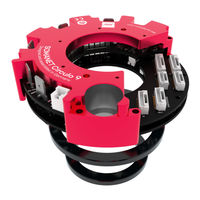
SYNAPTICON SOMANET Circulo Series Manuals
Manuals and User Guides for SYNAPTICON SOMANET Circulo Series. We have
5
SYNAPTICON SOMANET Circulo Series manuals available for free PDF download: Manual, Hardware Manual, Installation Manual
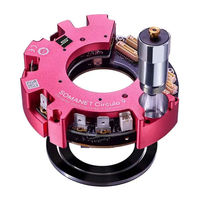
SYNAPTICON SOMANET Circulo Series Manual (887 pages)
Brand:
SYNAPTICON
| Category:
Servo Drives
| Size: 41 MB
Table of Contents
Table of Contents
2
0X2402 Analog Input
2
0X2502 Digital Input
2
0X2603 Digital Output
3
1 Hardware Manuals
20
Handling Instructions
25
Electrostatic Discharge
25
Magnetic Sensitive Devices
26
SOMANET Circulo
27
Technical Specifications
32
Power Specification
32
General Specification
33
Optional Integrated Encoders
34
Accuracy and Repeatability of the Integrated Encoders
36
Functions
37
Magnetic Data
37
Optional Integrated Brake
37
Ordering Information
38
Downloads
39
CAD Files
39
Documents
39
Installation Guide
40
Wiring Instructions
41
Power Supply, Phases and Brake
43
Power Terminal and Motor Phases
43
Connecting a Brake
46
Encoder Overview
48
Encoders and IO
48
Analog Input
49
Encoder Ports
50
Digital IO
55
Ethercat / STO-SBC in & out
57
Analog Input Specification
61
Differential
61
Single-Ended
62
Temperature Sensor
63
Specification for the Single-Ended Temperature Sensor Input
65
Selecting and Attaching a Battery for Multi-Turn
66
Suitable Encoder Batteries
66
Circulo Hybrid Ethercat - STO Cable
67
Overview
67
Pinout of the Connectors
68
Instructions for Manufacturing the Cables
70
Maximum Cable Lengths
76
Connector Details and Mating Part Numbers
77
Mating Parts
77
Mechanical Integration
79
Circulo Mounting Example
80
Mounting the Encoder Disc
81
Mounting a Hollow-Shaft Secondary Bearing
82
Routing the Motor Phase Cables
83
Dimensions
85
Dimensions and CAD Downloads
85
Drilling Patterns for Mounting
87
Mounting a Bearing
89
Side View with Phase Connectors
90
Axial Distance Tolerances
92
Mounting the Encoder Rings
92
Planar Displacements
94
Encoder Calibration
96
Encoder Accuracy
97
Narrow Angle Errors (Encoder System-Specific Non-Linearity)
98
Wide Angle Error (Installation-Dependent Non-Linearity)
99
Detecting the Encoder Non-Linearity
100
Calibration Procedure
101
Performing the Procedure
101
Prerequisite
101
Troubleshooting
103
Encoder System Diagnostic
105
LED Signals
108
Legend
108
Overview
108
Firmware
109
Status LED
109
Bootloader
110
Ethercat LED
110
Safety Functions (STO-SBC)
111
Safety Specifications
112
System Requirements
112
Technical Specifications
112
Safety Connectors
115
Cabling Lenghts
116
Connection Diagrams for the STO Inputs
116
Wiring the Safety Inputs
116
Manual Switch + Drives
117
Safety PLC PM (Plus-Minus Output) + Drives
117
Connection Diagram for the Brake
118
Safety PLC PP (Plus-Plus Output) + Drives
118
Timing Diagram for STO-Function Without Connected Brake
119
Timing Diagrams
119
Using the Safety Functions
119
Timing Diagram for STO-Function with SBC-Function
120
Diagnostic Functions
122
Software Diagnostics
122
STO-SBC Status Register
122
Truth Table for Digital Inputs
122
Examples for Realising Safety Functions
124
Emergency Stop
125
Prerequisites
126
Stop Category 1 Emergency Stop (Safe Stop 1)
126
Configuration
127
Wiring
127
Verification
128
Prevention of Unexpected Start-Up
129
Commissioning
130
Commissioning and Maintenance
130
Maintenance
130
Changelog of the Safety-Related Documentation
131
SOMANET Circulo (Sample. B.1)
132
Power Specification
135
Technical Specifications
135
General Specification
136
Optional Integrated Encoders
137
Accuracy and Repeatability of the Integrated Encoders
139
Optional Integrated Brake
140
Ordering Information
141
Installation Guide
142
Wiring Instructions
143
Power Supply, Phases and Brake
145
Encoders and IO
151
Temperature Sensor
165
Circulo Hybrid Ethercat - STO Cable
167
Mating Parts
175
Dimensions
177
Dimensions and Mechanical Mounting
177
Drilling Patterns for Mounting
180
Heat Dissipation
182
Aligning the Encoder Discs
183
Mounting the Encoder Rings
183
Mounting Tolerances
185
Selecting and Attaching a Battery for Multi-Turn
186
Mounting a Bearing
188
Encoder Accuracy
190
Narrow Angle Error (Short Wave Error, Differential Nonlinearity, Sub Divisional Error)
191
Wide Angle Error (Long Wave Error, Integral Nonlinearity)
191
Encoder Calibration
192
Overview
192
Encoder System Diagnostic
193
Prerequisite
193
Calibration Procedure
195
LED Signals
197
Legend
197
Overview
197
Firmware
198
Status LED
198
Bootloader
199
Ethercat LED
199
Safety Functions (STO-SBC)
200
Safety Specifications
201
System Requirements
201
Technical Specifications
201
Safety Connectors
204
Cabling Lenghts
205
Connection Diagrams for the STO Inputs
205
Wiring the Safety Inputs
205
Connection Diagram for the Brake
207
Timing Diagrams
209
Using the Safety Functions
209
Diagnostic Functions
211
Truth Table for Digital Inputs
211
STO-SBC Status Register
212
Examples for Realising Safety Functions
213
Emergency Stop
214
Stop Category 1 Emergency Stop (Safe Stop 1)
215
Prevention of Unexpected Start-Up
218
Commissioning
219
Commissioning and Maintenance
219
Maintenance
219
Changelog of the Safety-Related Documentation
220
SOMANET Node
221
SOMANET Node Revisions
223
SOMANET Node Rev
224
Power Specifications
225
Technical Specifications
225
General Specifications
226
Maximum Values
227
Load Cycle
228
CAD Files
229
Documents
229
Downloads
229
Ethercat Module
230
Hardware Diagrams
230
Processor Module
231
Drive Module
232
Installation Guide
233
Overview of Connectors
234
Wiring Instructions
234
Power Supply, Phases and Brake
235
Encoders and IO
240
Connector Details and Mating Parts Numbers
248
Heat Dissipation
249
Mounting Instructions
249
Thermal Mounting Considerations
249
Dimensions
251
Interference with Magnetic Fields
252
Branch Fuse Required
254
On-Site Installation Guide (UL)
254
Field Wiring Terminal Marking
255
Downloads
256
LED Signals
257
Legend
257
Overview
257
Core LED
258
Firmware
258
Bootloader
259
Drive LED
259
Com LED
260
SOMANET Node Safety (Original Instructions)
261
Dimensions
262
Specifications of the Safety Functions
263
System Requirements
263
Technical Specifications
263
Block Diagram
265
Setup of the Safety Functions
266
Connecting the STO/SBC Inputs
267
Connection Diagram for the Brake
270
Connector Mating Parts and Cable Lengths
272
Timing Diagrams
273
Using the Safety Functions
273
Diagnostic Functions
276
Truth Table for Digital Inputs
276
STO-SBC Status Register
277
Examples for Realising Safety Functions
279
Prevention of Unexpected Start-Up
279
Stop Category 0 (STO)
279
Stop Category 1 (SS1)
280
Commissioning
283
Commissioning and Maintenance
283
Maintenance
283
Changelog of the Safety-Related Documentation
284
SOMANET Accessories
285
SOMANET Braking Chopper 48V 500W
286
Overview
286
Technical Specs
287
Installing the Module and Setting the Threshold Voltage
288
Connecting the Board to DC-BUS
289
Suitable Cables
289
Wiring
289
Failsafe Behavior
290
Multi-Board Option
290
Led
291
Dimensions
292
Sin/Cos Encoder Cable Adapter
293
Block Diagram
293
Overview
293
Connectors
294
Encoder Connector Top
294
Encoder Connector Bottom
295
Interface Connector
295
Mounting Remarks
296
Soldered Cables
297
Strain Relief
297
Industrial I/O Cable Adapter
298
Block Diagram
298
Overview
298
Connector Details and Mating Parts
300
Pinouts
300
Strain Relief
301
Soldered Cables
302
Abi/Biss Encoder Cable Adapter
303
Block Diagram
303
Overview
303
Connectors
304
Encoder Connector Top
304
Encoder Connector Bottom
305
Interface Connector
305
Mounting Remarks
306
Downloads
307
Soldered Cables
307
Strain Relief
307
2 Commissioning and Tuning with SOMANET OBLAC Drives
308
OBLAC Drives Setup
309
OBLAC Drives Box
310
Connectors
310
Installation
311
Open OBLAC Drives
312
Powering the Box off and Resetting
312
Sharing a Connection with Your Host-PC
313
Using OBLAC Drives Box with Wifi
313
Connecting to the Internet
315
Update OBLAC Drives
316
OBLAC Drives Virtual Machine
317
Getting Started
317
Prerequisite
317
Connecting to OBLAC Drives
324
Update OBLAC Drives
326
Troubleshooting
327
Using OBLAC Drives
328
Installing the Latest Version
328
User Interface Overview
329
Save to Device
329
Update Firmware
329
Download Device Description XML
330
Download Log
330
Factory Reset
330
Launch Setup Wizard
330
Load Configuration File
330
Save Configuration File
330
Using Keyboard Shortcuts
331
Quick Open
331
Set up Your Servo Drive
332
Motion Control Tuning
339
Overview of the Tools
339
Auto-Tuning
340
Concept of Auto-Tuning
340
Goal of Position Auto-Tuning
340
Goal of Velocity Auto-Tuning
341
Limitations
342
Prerequisites
342
System Identification
342
How to Use
343
345
345
How to Use
347
Limitations
347
Position Auto-Tuning
347
Prerequisites
347
F.a.q
352
Next Steps
352
How to Use
354
Limitations
354
Prerequisites
354
Velocity Auto-Tuning
354
F.a.q
357
Next Steps
357
Manual Tuning
358
Manual Tuning Guide
359
Manual Tuning of the Current Controller
359
Manual Tuning of the Velocity Control Loop
361
Manual Tuning of the Position Control Loop: Cascaded Controller
362
Test Your Drive at the Playground
363
Prerequisites
363
Apply a Defined Torque to Your Motor
363
Rotate Your Motor at Defined Velocities
364
Rotate Your Motor to Defined Positions
364
Update/Downgrade OBLAC Drives
366
Troubleshooting
367
Virtualization Not Activated
367
Memory Warning
368
Runtime Issues
368
Other Issues
369
3 Software Reference
370
Software Reference Manual V5.0
378
Firmware Overview
381
Functionality Description
382
Canopen over Ethercat (Coe)
383
Drive State Machine (Cia 402)
383
Pdo
384
PDO Configuration
384
Sdo
384
Actuator Configuration
385
Motor and Gear Settings
386
Motor Configuration
386
Pole Pairs
386
Torque Constant
386
Phase Inductance
387
Phase Resistance
387
Errors in Phase Resistance and Inductance
388
Motor Phases Inverted
388
Advanced Motor Configurations
389
Gear Ratio
389
Selecting the PWM Frequency
389
Parameters Related to Motor and Gear Settings
390
Controlling a Generic Voltage at the Brake Output
391
Overview
391
Usage
391
Limitations
392
Parameters Related to Controlling the Brake Output Voltage
392
Brake Configuration
393
Pin-Brake Mode
394
Timing Diagram
394
Custom Brake Modes
396
Parameters Related to the Brake
396
Selecting the PWM Frequency of the Brake
396
Overview
397
Usage
397
User Defined Velocity Units
397
Objects Affected by Changes of the Velocity Unit
398
Example
399
Parameters Related to User Defined Velocity Units
400
Basic Principles
401
Commutation Offset Detection
401
Overview
401
Load Requirements
403
Requirements
403
Autophasing Methods
404
Method 0
404
Method 1
404
Method 2
405
Common Use Cases
406
Usage
407
Parameters Related to Commutation Sensor Offset Measurement
408
Tuning the Gains for Method
408
Detailed Description
410
Overview
410
Power Limit
410
Requirements
410
Parameters Related to Power Limit
411
Encoders and I/O
412
Analog in
413
Nonlinear Conversion of an Analog Voltage
413
Using Differential Inputs for Single-Ended Sensors
413
Parameters Related to Analog Inputs
414
External Scaled Measurement
415
Requirements
415
Usage
415
Configuration of Digital I/Os as Input or Output
419
Digital I/O
419
Parameters Related to Digital I/O
419
Using Digital I/Os for Input Actions or Output Events
419
Digital GPIO
420
Overview
420
Usage
421
Parameters Related to Digital GPIO
428
Description of Common Encoder Parameters
429
Encoder Configuration
429
Function
429
Polarity
429
Resolution
429
Zero Velocity Threshold
429
Encoder Related Parameters
430
Multiturn Resolution
430
Commutation with Hall and ABI Combined
431
Overview
431
Requirements
431
Usage
431
Detailed Description
432
Error Detection
432
Runtime
432
Startup
432
Input Counter
433
Limitations
433
Overview
433
Parameters Related to Input Counter
434
Protection
435
Overview
435
Parameters Related to Protection
435
Usage
435
Errors and Warnings
436
Error Codes Thrown by the Firmware
437
Error Report Object
438
Logging
457
Format
457
Overview
457
Types
457
Motion Control
458
Control Loops
460
Current and Torque Control Loop
461
Torque Control Loop
461
Parameters Related to Current and Torque Control Loop
464
Velocity Control Loop
465
Parameters Related to the Velocity Control Loop
466
Cascaded PID Controller
467
Position Control Loops
467
Simple PID Controller
468
Dual Loop Cascaded Position Control
470
Overview
470
Parameters Related to Dual Loop Cascaded Position Control
471
Usage
471
Modes of Operation
472
Cyclic Modes
473
Cyclic Synchronous Torque Mode
474
Cyclic Synchronous Velocity Mode
476
Cyclic Synchronous Position Mode
479
Profile Modes
481
Profile Position Mode
482
Profile Velocity Mode
490
Profile Torque Mode
494
Homing Methods
497
Homing Modes
497
Overview
497
Settings for Homing Mode
502
How to Perform Homing
504
Operation Mode Dependent Bits of Status- and Controlword
506
Parameters Related to Homing Mode
507
Overview
508
Quick Stop
508
Usage
508
Parameters Related to Quick Stop
511
Diagnostics Opmode
512
Dynamic Op-Mode Switching
513
Selecting and Switching the Modes
513
Extended Control Functionalities
514
Cogging Torque Compensation
515
Overview
515
Procedure
516
Controlling the Feature Via Ethercat
519
Subitems
519
Parameters Related to Cogging Torque Compensation
520
Field Weakening
521
Anti-Windup Control
523
Parameters Related to Anti-Windup Control
524
Gain Scheduling
525
Description of Subitems for 0X200A
527
Motor Overload Protection (I2T)
527
Overview
527
Requirements
527
Operating Principle
528
Usage
529
Velocity Feed Forward
529
Object Used for Velocity Feed Forward
530
Using a Velocity Offset Additionally
530
Torque Offset
531
Velocity Offset
532
Filtering
533
Overview
533
Methods
535
Application Guide
536
Parameters Related to Filters
536
Position and Velocity Feedback Low-Pass Filters
537
Torque Loop Input Shaping Filter
539
Command Smoothing and Interpolation
541
Overview
541
Side Effects
541
Applications
542
Detailed Description
543
Control Supervision
546
Timing Diagram of the Supervision Objects
546
Following Error
549
Following Error Window
549
Target Reached Function
551
Monitoring the Internal Variables
553
Control Effort
554
Parameters Related to Control Supervision
554
Distributed Clock Configuration
556
Distributed Clocks (DC Clocks)
556
Overview
556
Parameters Related to Distributed Clocks
557
OS Command
558
Overview
558
Usage
558
Cia 402 Object Dictionary
560
List of All Objects
561
0X1000 Device Type
574
0X1001 Error Register
575
0X1005 COB-ID SYNC
576
0X1006 Communication Cycle Period
577
0X1008 Manufacturer Device Name
578
0X100A Manufacturer Software Version
579
0X100C Guard Time
580
0X100D Life Time Factor
581
0X1010 Store Parameters
582
0X1011 Restore Default Parameters
583
0X1016 Consumer Heartbeat Time
584
0X1017 Producer Heartbeat Time
585
0X1018 Identity Object
586
0X1019 Synchronous Counter Overflow Value
587
0X1023 os Command
588
0X1024 os Command Mode
589
0X1400 Receive PDO1 Parameter
590
0X1401 Receive PDO2 Parameter
591
0X1402 Receive PDO3 Parameter
592
0X1403 Receive PDO4 Parameter
593
0X1600 Receive PDO1 Mapping
594
0X1601 Receive PDO2 Mapping
595
0X1602 Receive PDO3 Mapping
596
0X1603 Receive PDO4 Mapping
597
0X1800 Transmit PDO1 Parameter
598
0X1801 Transmit PDO2 Parameter
599
0X1802 Transmit PDO3 Parameter
600
0X1803 Transmit PDO4 Parameter
601
0X1A00 Transmit PDO1 Mapping
602
0X1A01 Transmit PDO2 Mapping
603
0X1A02 Transmit PDO3 Mapping
604
0X1A03 Transmit PDO4 Mapping
605
0X1C00 Sync Manager
606
0X1C10 SM 0 Assignment
607
0X1C11 SM 1 Assignment
608
0X1C12 SM 2 Assignment
609
0X1C13 SM 3 Assignment
610
0X2000 Command Object (Disabled)
611
0X2001 Commutation Angle Offset
612
0X2002 Position Control Strategy
613
Selects the Control Structure Used for Position Control
613
0X2003 Motor Specific Settings
614
0X2004 Brake Options
615
0X2005 Recuperation
618
0X2006 Protection
619
0X2008 Cogging Torque Compensation
620
0X2009 Commutation Offset
621
0X200A I2T
624
0X200B Max Power
625
0X2010 Torque Controller
626
0X2011 Velocity Controller
629
Velocity PID Tuning (Objects 2011:1
629
0X2012 Position Controller
631
Parameter Tuning Guide for Position Controller with Cascaded Structure
631
Parameter Tuning Guide for Position Controller with Simple PID Structure (Objects 2012:1
633
0X2012 Position Controller
635
Parameter Tuning Guide for Position Controller with Cascaded Structure
635
Parameter Tuning Guide for Position Controller with Simple PID Structure (Objects 2012:1
637
0X2013 Gain Scheduling
639
0X2014 Torque Window
642
0X2015 Velocity Feed Forward
643
0X2021 Velocity Feedback Filter
644
0X2022 Position Feedback Filter
645
0X2023 Notch Filter
646
0X2027 Control Input FIR Filter
647
0X2030 Core Temperature
648
0X2031 Drive Temperature
649
0X2038 External Scaled Measurement
650
0X203F Error Report
652
0X2040 Input Counter
671
0X20E1 High Resolution Data
672
0X20F0 Timestamp
674
0X20F2 Assigned Name
675
0X20F3 DC Synchronization
676
0X2100 Feedback Sensor Ports
677
0X21Ff Singleturn Offset
680
0X2201 Biss Encoder
681
0X2202 Biss Encoder
685
0X2203 REM 16MT Encoder
689
0X2205 Incremental Encoder
691
0X2206 Incremental Encoder
693
0X2207 Hall Sensor
695
0X2208 Hall Sensor
697
0X2209 SSI Encoder
699
0X220A SSI Encoder
703
0X220B a Format Encoder
707
0X220C Fast ABI Module
709
0X220E Sincos Module
712
0X2210 GPIO Pin Configuration
715
0X2211 GPIO Output Events
726
0X2212 GPIO Input Actions
727
0X2213 GPIO Position Trigger
728
0X2214 GPIO Global Options
729
0X230A Secondary Position Value
730
0X230B Secondary Velocity Value
731
0X2401 Analog Input
732
0X2403 Analog Input
734
0X2404 Analog Input
735
0X2501 Digital Input
736
0X2503 Digital Input
738
0X2504 Digital Input
739
0X2601 Digital Output
740
0X2602 Digital Output
741
0X2604 Digital Output
743
0X2611 Safety Digital Input Diagnostics
744
0X2701 Tuning Command
745
0X2702 Tuning Status
746
0X2703 User MOSI
747
0X2704 User MISO
748
0X2705 Setup Wizard Completed
749
0X603F Error Code
750
0X6040 Controlword
751
0X6041 Statusword
752
0X605A Quick Stop Option Code
754
0X6060 Modes of Operation
755
0X6061 Modes of Operation Display
756
0X6062 Position Demand Value
757
0X6064 Position Actual Value
758
0X6065 Following Error Window
759
0X6066 Following Error Time out
760
0X6067 Position Window
761
0X6068 Position Window Time
762
0X606B Velocity Demand Value
763
0X606C Velocity Actual Value
764
0X606D Velocity Window
765
0X606E Velocity Window Time
766
0X606F Velocity Threshold
767
0X6070 Velocity Threshold Time
768
0X6071 Target Torque
769
0X6072 Max Torque
770
0X6073 Max Current
771
0X6074 Torque Demand
772
0X6075 Motor Rated Current
773
0X6076 Motor Rated Torque
774
0X6077 Torque Actual Value
775
0X6079 DC Link Circuit Voltage
776
0X607A Target Position
777
0X607B Position Range Limit
778
0X607C Home Offset
779
0X607D Software Position Limit
780
0X607E Polarity
781
0X6080 Max Motor Speed
782
0X6081 Profile Velocity
783
0X6083 Profile Acceleration
784
0X6084 Profile Deceleration
785
0X6085 Quick Stop Deceleration
786
0X6086 Motion Profile Type
787
0X6087 Torque Slope
788
0X6088 Torque Profile Type
789
0X6091 Gear Ratio
790
0X6098 Homing Method
791
0X6099 Homing Speeds
792
0X609A Homing Acceleration
793
0X60A9 si Unit Velocity
794
0X60B1 Velocity Offset
795
0X60B2 Torque Offset
796
0X60E3 Supported Homing Methods
797
0X60F4 Following Error Actual Value
798
0X60Fa Control Effort
799
0X60Fc Position Demand Internal Value
800
0X60Fd Digital Inputs
801
0X60Fe Digital Outputs
802
0X60Ff Target Velocity
803
0X6502 Supported Drive Modes
804
0X6621 Safety Statusword
805
Communication Area
806
Process Data Objects
810
Standard Rxpdo Mapped Objects
811
Standard Txpdo Mapped Objects
812
Advanced PDO Mapping
813
Changing the Content of an Object
813
Manufacturer Specific Area
815
Profile Specific Area
823
Device Information
825
Overview
826
Saving and Restoring Configurations
826
Restore Configuration
827
Usage
827
Parameters Related to Saving and Restoring Configurations
828
Save Configuration
828
Advertisement
SYNAPTICON SOMANET Circulo Series Hardware Manual (224 pages)
Brand:
SYNAPTICON
| Category:
Servo Drives
| Size: 15 MB
Table of Contents
Table of Contents
2
Hardware Manuals
8
Handling Instructions
14
Electrostatic Discharge
14
Magnetic Sensitive Devices
15
SOMANET Circulo
16
Overview
20
Technical Specifications
23
Power Specification
23
General Specification
23
Optional Integrated Encoders
25
Accuracy and Repeatability of the Integrated Encoders
27
Optional Integrated Brake
28
Ordering Information
29
Load Cycle
30
Thermal Mounting Considerations
31
Current as a Function of Mounting Temperature
32
Ambient Air
34
Downloads
35
Documents
35
CAD Files
35
Installation Guide
36
Wiring Instructions
37
Power and Brake
39
Supply and Phases
39
Connecting a Brake
42
Encoders and IO
44
Encoder Overview
44
Analog Input
45
Encoder Ports
46
Digital IO
51
Ethercat / STO-SBC in & out
53
Analog Input Specification
58
Differential
58
Single-Ended
59
Temperature Sensor
60
Specification for the Single-Ended Temperature Sensor Input
62
Battery for Multi-Turn
64
Suitable Batteries
64
Ethercat-STO Cable
65
Overview
65
Pinout of the Connectors
66
Instructions for Manufacturing the Cables
69
Maximum Cable Lengths
74
Mating Parts
75
Connector Details and Mating Part Numbers
75
Mechanical Integration
77
Circulo Mounting Example
78
Mounting the Encoder Disc
79
Mounting a Hollow-Shaft Secondary Bearing
80
Routing the Motor Phase Cables
81
Dimensions and Drawings
83
Dimensions
83
Weight and Inertia of the Encoder Rings
87
Drilling Patterns
87
Mounting a Bearing
90
Side View with Phase Connectors
91
Mounting Encoder Rings
93
Axial Distance Tolerances
93
Planar Displacements
95
Encoder Calibration
97
Encoder Accuracy
98
Narrow Angle Errors (Encoder System-Specific Non-Linearity)
99
Wide Angle Error (Installation-Dependent Non-Linearity)
100
Detecting the Encoder Non-Linearity
101
Calibration Procedure
102
Prerequisite
102
Performing the Procedure
102
Troubleshooting
107
Encoder System Diagnostic
109
LED Signals
115
Overview
115
Legend
115
Status LED
116
Firmware
116
Bootloader
117
Ethercat LED
117
Safety Functions (STO-SBC)
118
Safety Specifications
119
System Requirements
119
Technical Specifications
119
Safety Connectors
122
Wiring the Safety Inputs
123
Cabling Lenghts
123
Connection Diagrams for the STO Inputs
123
Manual Switch + Drives
124
Safety PLC PM (Plus-Minus Output) + Drives
124
Safety PLC PP (Plus-Plus Output) + Drives
125
Connection Diagram for the Brake
125
Using the Safety Functions
126
Timing Diagrams
126
Timing Diagram for STO-Function Without Connected Brake
126
Timing Diagram for STO-Function with SBC-Function
127
Truth Table for Digital Inputs
129
Diagnostic Functions
129
Software Diagnostics
129
STO-SBC Status Register
129
Examples for Realising Safety Functions
131
Emergency Stop
132
Stop Category 1 Emergency Stop (Safe Stop 1)
133
Prerequisites
133
Wiring
134
Configuration
134
Verification
135
Prevention of Unexpected Start-Up
136
Commissioning and Maintenance
137
Commissioning
137
Maintenance
137
Changelog of the Safety-Related Documentation
138
SOMANET Node
139
SOMANET Node Revisions
141
SOMANET Node Rev
142
Overview
143
Technical Specifications
144
Power Specifications
144
General Specifications
144
Load Cycle
147
Thermal Mounting Considerations
148
Downloads
150
Documents
150
CAD Files
150
Installation Guide
151
Wiring Instructions
152
Overview of Connectors
152
Power and Brake
153
Encoders and IO
158
Connector Details and Mating Parts Numbers
167
Mounting Instructions
168
Heat Dissipation
168
Dimensions
168
Interference with Magnetic Fields
170
On-Site Installation Guide (UL)
171
Branch Fuse Required
171
Field Wiring Terminal Marking
172
Downloads
173
LED Signals
174
Overview
174
Legend
174
Core LED
175
Firmware
175
Bootloader
176
Drive LED
176
Com LED
177
SOMANET Node Safety (Original Instructions)
178
Dimensions
179
Specifications of the Safety Functions
180
System Requirements
180
Technical Specifications
180
Block Diagram
182
Setup of the Safety Functions
183
Connecting the STO/SBC Inputs
184
Connection Diagram for the Brake
187
Connector Mating Parts and Cable Lengths
189
Using the Safety Functions
190
Timing Diagrams
190
Truth Table for Digital Inputs
193
Diagnostic Functions
193
STO-SBC Status Register
194
Examples for Realising Safety Functions
196
Prevention of Unexpected Start-Up
196
Stop Category 0 (STO)
196
Stop Category 1 (SS1)
197
Commissioning and Maintenance
200
Commissioning
200
Maintenance
200
Changelog of the Safety-Related Documentation
201
SOMANET Accessories
202
SOMANET Braking Chopper 48V 500W
203
Overview
203
Technical Specs
204
Installing the Module and Setting the Threshold Voltage
205
Connecting the Board to DC-BUS
206
Suitable Cables
206
Wiring
206
Failsafe Behavior
207
SYNAPTICON SOMANET Circulo Series Installation Manual (35 pages)
Brand:
SYNAPTICON
| Category:
Servo Drives
| Size: 3 MB
Table of Contents
Table of Contents
2
Installation Guide
4
Wiring Instructions
5
Overview of Connectors
5
Power Supply and Motor Brake
6
Power Terminal
6
Motor Phases
6
Using a PELV or SELV Power Supply
7
Warning about Using Contactors Behind the Power Supply
7
Connecting a Brake
8
Encoders and IO
10
Connector Overview
10
Analog Input
10
External Encoder
11
Possible Combinations
12
Digital IO
13
Safety STO-SBC
14
Encoder Battery (for Multi-Turn)
16
Ethercat In/Out
16
Temperature Sensor
18
Mating Parts and Encoder Battery
19
Connector Details and Mating Part Numbers
19
Suitable Encoder Batteries
21
Dimensions and Mechanical Mounting
22
Dimensions
22
Drilling Patterns for Mounting
25
Heat Dissipation
27
Downloads
28
Mounting the Encoder Disks
29
Aligning the Encoder Discs
29
Mounting Tolerances
32
Radial Displacement (R)
32
Tangential Displacement (T)
32
Axial Distance
32
Tilt Angle
33
Mounting Eccentricity (Rotation Axis Offset)
33
Advertisement
SYNAPTICON SOMANET Circulo Series Hardware Manual (9 pages)
Brand:
SYNAPTICON
| Category:
Servo Drives
| Size: 0 MB
Table of Contents
Table of Contents
2
Encoders and IO
3
Connector Overview
3
Analog Input
3
External Encoder
4
Possible Combinations
5
Digital IO
6
Safety STO-SBC
7
Encoder Battery (for Multi-Turn)
8
Ethercat In/Out
9
SYNAPTICON SOMANET Circulo Series Manual (6 pages)
Power supply and motor brake
Brand:
SYNAPTICON
| Category:
DC Drives
| Size: 0 MB
Table of Contents
Table of Contents
2
Power Supply and Motor Brake
3
Power Terminal
3
Motor Phases
3
Using a PELV or SELV Power Supply
4
Warning about Using Contactors Behind the Power Supply
4
Connecting a Brake
5
Advertisement
Related Products
SYNAPTICON SOMANET Node Series
SYNAPTICON SOMANET Circulo
SYNAPTICON SOMANET OBLAC Drives Box
SYNAPTICON SOMANET
SYNAPTICON SOMANET Node
SYNAPTICON SOMANET Node 1000
SYNAPTICON SOMANET Node 2000
SYNAPTICON SOMANET Node 400
SYNAPTICON Categories
Servo Drives
DC Drives
Industrial Equipment
Computer Hardware
Wireless Access Point
More SYNAPTICON Manuals
Login
Sign In
OR
Sign in with Facebook
Sign in with Google
Upload manual
Upload from disk
Upload from URL