Sign In
Upload
Manuals
Brands
ST Manuals
Computer Hardware
B-WL5M-SUBG1 STM32WL
ST B-WL5M-SUBG1 STM32WL Manuals
Manuals and User Guides for ST B-WL5M-SUBG1 STM32WL. We have
1
ST B-WL5M-SUBG1 STM32WL manual available for free PDF download: User Manual
ST B-WL5M-SUBG1 STM32WL User Manual (47 pages)
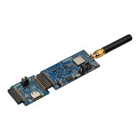
Connectivity expansion board
Brand:
ST
| Category:
Computer Hardware
| Size: 3 MB
Table of Contents
Figure 1. B-WL5M-SUBG1 Product
1
Features
2
Ordering Information
3
Codification
3
Table 1. List of Available Products
3
Table 2. Codification Explanation
3
Development Environment
4
System Requirements
4
Development Toolchains
4
Conventions
5
Table 3. ON/OFF Convention
5
Quick Start
6
Getting Started
6
Table 4. Jumper Default Configuration
6
Hardware Layout and Configuration
7
CEB MB1779 Board
7
MB1779 PCB Layout
7
Figure 2. MB1779 Hardware Block Diagram
7
Figure 3. MB1779 Top Layout
7
MB1779 Mechanical Drawing
8
Figure 4. MB1779 Bottom Layout
8
Figure 5. MB1779 Mechanical Drawing
8
MB1880 Stmod+ Adapter Board
9
MB1880 PCB Layout
9
Figure 6. MB1880 Basic Hardware Block Diagram
9
Figure 7. MB1880 Top Layout
9
MB1880 Mechanical Drawing
10
Figure 8. MB1880 Bottom Layout
10
Figure 9. MB1880 Mechanical Drawing (in Millimeters)
10
Power Supply
11
Figure 10. CEB MB1779 Board Power Tree
11
Power Supply Input E5V Connector (Default Setting)
12
Table 5. External Power Source E5V (5 V)
12
Figure 11. E5V and GND Pins on CN4
12
Power Via the Stmod+ Adapter Board (MB1880) Supplied through a USB Type-C
13
Connector
13
Power Via Stmod+ Adapter Board (MB1880) Supplied through a Host
13
Table 6. External Power Source 5V (5 V)
13
Figure 12. Power Supply Input from 5V Via the Stmod+ Adapter Board (MB1880) Connected to a PC through a USB Connector
13
Figure 13. Power Supply Input from 5V Via Stmod+ Adapter Board (MB1880) Connected to a Host
13
Power Supply Input E3V3 Connector
14
Table 7. External Power Source E3V3 (3.3 V)
14
Figure 14. E3V3 and GND Pins on CN5
14
Board Functions
15
Leds
15
Push-Buttons
15
RF Overview
15
Figure 15. RF Block Diagram
16
Figure 16. FCC Identifier on the STM32WL5MOC Module
16
Figure 17. Schematic Focus on the RF Part
17
Figure 18. HP Configuration Without DC Switches
17
Figure 19. LP Configuration Without DC Switches
17
Table 8. RF Transceiver Configuration
18
Figure 20. HP Configuration with DC Switches
18
Figure 21. LP Configuration with DC Switches
18
Trace Antenna Design
19
Table 9. Antenna Design Requirements
19
Figure 22. Reference Schematic Design at the Antenna Interface
19
Figure 23. Microstrip Design on a 2-Layer PCB
20
Figure 24. Coplanar Waveguide Design on a 2-Layer PCB
20
Stsafe
21
Figure 25. STSAFE Supplied by PB8 (VDD Guaranteed above 2.6 V)
21
Current Consumption Measurement (IDD)
22
Figure 26. JP2 Settings for Current Consumption Measurement
22
Solder Bridges
23
Table 10. Solder Bridge Configuration on MB1779
23
Table 11. Solder Bridge Configuration on MB1880
25
Jumpers
26
MB1779 Jumper
26
MB1880 Jumpers
26
Table 12. Consistent JP (MB1880) and SB (MB1779) Settings for SPI or UART Functions
26
Embedded Devices
27
Temperature Sensor (U14)
27
Accelerometer and 3D Gyroscope (U2)
27
Table 13. I 2 C Addresses
27
Figure 27. 3D Direction for Acceleration and Angular Rate
27
Barometer (U4)
28
Magnetometer (U7)
28
Figure 28. 3D Accelerometer and 3D Gyroscope (U2) Pin 1 Location
28
Figure 29. Direction of Detectable Magnetic Fields
28
Figure 30. Magnetometer (U7) Pin 1 Location
28
Board Connectors
29
MB1779 Stmod+ (CN1)
29
Table 14. Stmod+ Connector (CN1) Pinout
29
Figure 31. Stmod+ Connector (CN1)
29
MB1779 Debugging Connector (CN3)
31
Table 15. STDC14 Connector (CN3) Pinout
31
Figure 32. STDC14 Debugging Connector (CN3) Top View
31
STLINK-V3E Debugger
32
MB1779 2-Pin E5V Connector (CN4)
32
Table 16. External Power Source E5V (5 V)
32
Figure 33. Connecting an External Debug Tool to Program the CEB MB1779
32
Figure 34. 2-Pin 2.54 MM E5V Connector (CN4)
32
MB1779 2-Pin E3V3 Connector (CN5)
33
MB1880 USB-C ® Connector (CN1)
33
Table 17. External Power Source E3V3 (3.3 V)
33
Figure 35. 2-Pin 2.54 MM E3V3 Connector (CN5)
33
MB1880 Stmod+ Connectors (CN2 and CN3)
34
Table 18. Stmod+ Pin Assignment and Description
34
STM32WL5MOC I/O Assignment
35
Table 19. STM32WL5MOC I/O Assignment
35
WL5M-SUBG1 Product Information
37
Product Marking
37
B-WL5M-SUBG1 Product History
37
Table 20. Product History
37
Board Revision History
38
Table 21. Board Revision History
38
Federal Communications Commission (FCC) and ISED Canada Compliance
39
Statements
39
FCC Compliance Statement
39
ISED Compliance Statement
40
RED Compliance Statement
41
Revision History
42
Table 22. Document Revision History
42
Table of Contents
43
List of Tables
45
List of Figures
46
Advertisement
Advertisement
Related Products
ST B-WB1M-WPAN1
ST B-U585I-IOT02A
ST B-G473E-ZEST1S
ST B-LCDAD-HDMI1
ST STM32WL Series
ST STM32WL5MOC
ST BC 556
ST BC 50 H
ST B 26 JA
ST B 26 DA
ST Categories
Motherboard
Computer Hardware
Microcontrollers
Control Unit
Controller
More ST Manuals
Login
Sign In
OR
Sign in with Facebook
Sign in with Google
Upload manual
Upload from disk
Upload from URL