Sign In
Upload
Manuals
Brands
ST Manuals
Computer Hardware
B-G473E-ZEST1S
ST B-G473E-ZEST1S Manuals
Manuals and User Guides for ST B-G473E-ZEST1S. We have
1
ST B-G473E-ZEST1S manual available for free PDF download: User Manual
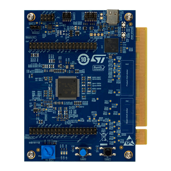
ST B-G473E-ZEST1S User Manual (38 pages)
Motor control Discovery kit
Brand:
ST
| Category:
Computer Hardware
| Size: 3 MB
Table of Contents
1 Features
2
Table 1. List of Available Products
3
Table 2. Codification Explanation
3
2 Ordering Information
3
Codification
3
3 Development Environment
4
System Requirements
4
Development Toolchains
4
Demonstration Software
4
Table 3. ON/OFF Convention
5
4 Conventions
5
5 Quick Start
6
6 Hardware Layout and Configuration
7
Hardware Block Diagram
7
Default Board Configuration
8
Table 4. Default Jumper Setting
8
Table 5. USB Type-C ® Connector (CN4) Pinout
9
Use of an External Debugging Tool to Program and Debug the On-Board STM32
10
Table 6. STDC14/MIPI10 Debug Connector Pinout
11
Firmware Upgrade
10
STDC14/MIPI10 and USART Connectors
10
Description
10
Embedded STLINK-V3EC
9
Description
9
Drivers
9
Table 7. Hardware I/O Configuration for the STDC14 Connector (CN2)
11
Table 8. USART Debug Connector Pinout
12
Table 9. Hardware I/O Configuration for the USART Connector (CN1)
12
Table 10. Power Source Capability
13
Table 11. BOOT Selection Switch
15
Description
16
MC Connector V2
16
Pinout
16
Table 12. MC Connector V2
16
Description
21
Hardware Configuration for MC Connector V2
21
I/O Restriction to Other Features
21
Morpho MC Connectors
21
Table 13. Hardware I/O Configuration for MC Connector V2
21
Pinout
22
5V STLINK-V3EC Source: 5V_USB_STLK
14
5V_CHG Power Source
14
Clock Sources
14
E5V Power Source
14
Programing/Debugging When the Power Supply Is Not from STLINK-V3EC (5V_STLK)
14
Reset Sources
15
Rss/Bootloader
15
Boot from RSS
15
Description
15
Table 14. Morpho MC Connector (CN7)
22
Table 15. Morpho MC Connector (CN10)
24
Table 16. Hardware I/O Configuration for the Morpho MC
25
Description
26
I/O Restriction to Other Features
26
LED Interface
26
Operational Amplifier
26
Operational Amplifier Interface
26
Physical Input Devices: Buttons
26
Physical Input I/O Interface
26
Table 17. Hardware I/O Configuration for the LED Interface
26
Table 18. Hardware I/O Configuration for the Physical User Interface
26
Analog Input, Potentiometer
27
Description
27
I/O Restriction to Other Features
27
Potentiometer
27
Hardware Configuration for Morpho MC
25
I/O Restriction to Other Features
25
User Leds
25
Description
25
I/O Restriction to Other Features
13
Power Supply
13
Power Supply General View
13
P5V Power Source
13
Table 19. Hardware I/O Configuration for the OPAMP Interface
27
Table 20. Hardware I/O Configuration for the Potentiometer
27
7 B-G473E-ZEST1S Product Information
28
Product Marking
28
B-G473E-ZEST1S Product History
29
Board Revision History
29
Table 21. Product History
29
Table 22. Board Revision History
29
8 Federal Communications Commission (FCC) and ISED Canada Compliance
30
Statements
30
FCC Compliance Statement
30
ISED Compliance Statement
30
9 CE Conformity
31
Warning
31
10 Certification Information
32
Table 23. Document Revision History
33
Table of Contents
34
Revision History
33
List of Tables
36
List of Figures
37
Advertisement
Advertisement
Related Products
ST B-WB1M-WPAN1
ST B-WL5M-SUBG1 STM32WL
ST B-U585I-IOT02A
ST B-LCDAD-HDMI1
ST BC 536 Series
ST BC 556
ST BC 900 D Li 48
ST BC 50 H
ST BlueNRG-LP
ST BL 20 Li B
ST Categories
Motherboard
Computer Hardware
Microcontrollers
Control Unit
Controller
More ST Manuals
Login
Sign In
OR
Sign in with Facebook
Sign in with Google
Upload manual
Upload from disk
Upload from URL