Sign In
Upload
Manuals
Brands
ST Manuals
Computer Hardware
B-U585I-IOT02A
User Manuals: ST B-U585I-IOT02A kit IoT node
Manuals and User Guides for ST B-U585I-IOT02A kit IoT node. We have
2
ST B-U585I-IOT02A kit IoT node manuals available for free PDF download: Quick Start Manual, User Manual
ST B-U585I-IOT02A User Manual (54 pages)
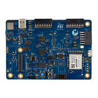
Discovery kit for IoT node with STM32U5 series
Brand:
ST
| Category:
Computer Hardware
| Size: 3 MB
Table of Contents
Figure 1. B-U585I-IOT02A Discovery Kit for the Iot Node
1
Features
2
Ordering Information
3
Codification
3
Table 1. Ordering Information
3
Table 2. Codification Explanation
3
Development Environment
4
System Requirements
4
Development Toolchains
4
Conventions
5
Table 3. ON/OFF Convention
5
Delivery Recommendations
6
Getting Started
7
Hardware Layout and Configuration
8
Figure 3. B-U585I-IOT02A Discovery Kit Layout (Top View)
9
Figure 4. B-U585I-IOT02A Discovery Kit Layout (Bottom View)
10
Figure 5. B-U585I-IOT02A Discovery Kit Mechanical Drawing in Millimeters
11
Embedded STLINK-V3E
12
Description
12
Drivers
12
STLINK-V3E Firmware Upgrade
12
Figure 6. USB Composite Device
12
Using an External Debug Tool to Program and Debug the On-Board STM32
13
Table 4. CN9 STDC14/MIPI10 Debug Connector Pinout
13
Figure 7. Connecting an External Debug Tool to Program the On-Board STM32
13
Table 5. TAG Connector Pinout
14
Figure 8. TAG Connector
14
Figure 9. TC2050-IDC-NL Cable
14
Power Supply
15
Figure 10. JP4: 5V_USB_STLK Selection
15
Figure 11. JP4: 5V_VIN Selection from CN17 (VIN)
16
Figure 12. JP4: 5V_UCPD
16
Figure 13. JP4: 5V_USB_CHGR Selection
17
Figure 14. Power Tree
18
Clock Source
19
MCU Management
19
Reset Sources
19
MCU Boot Switch and Jumper for Current Measurement
19
Table 6. I/O Configuration for the Optional HSE
19
Table 7. MCU Jumper and Switch
19
USB Type-C ® FS Port
20
Device and Host Modes
20
UCPD Description
20
USB Type-C
21
Table 8. USB Type-C ® FS Power Delivery Configuration
21
Table 9. USB Type-C ® Pinout
21
Figure 15. USB Type-C (Front View)
21
NOR Flash, PSRAM, and EEPROM Memories
22
Table 10. Octo-SPI Flash I/O Configuration
22
Table 11. Octo-SPI RAM I/O Configuration
22
Virtual COM Port
23
RF Modules
23
Bluetooth ® (V5.0 Compliant) STM32WB5MMG
23
Figure 16. STM32WB5MMG RF Module
23
Bluetooth ® Low Energy Module Firmware Update
24
Table 12. Bluetooth ® Low Energy Module I/O Configuration
24
Figure 17. Bluetooth ® Low Energy Module Firmware Update Port
24
MXCHIP EMW3080 (802.11 B/G/N Compliant Wi-Fi ® Module)
25
Table 13. Bluetooth ® Low Energy Power Selection
25
Figure 18. EMW3080 Module
25
Table 14. WLAN Module I/O Configuration
26
Figure 19. EMW3080 Switch
26
Figure 20. Wi-Fi ® Firmware Update Configuration
27
Figure 21. Firmware Update Utility Menu
27
Figure 22. Firmware Update Utility Message
27
Mems
28
Two On-Board MEMS Audio Sensor Omnidirectional Digital Microphones
28
(Mp23Db01Hptr)
28
Table 15. I 2 C Addresses for MEMS
28
Figure 23. Firmware Update Utility Successful Completion
28
Capacitive Digital Sensor for Relative Humidity and Temperature (HTS221)
29
High-Performance 3-Axis Magnetometer (IIS2MDCTR)
29
Accelerometer and 3D Gyroscope (ISM330DHCX)
29
260 To 1260 Hpa Absolute Digital Output Barometer (LPS22HH)
29
Table 16. Microphones I/O Configuration
29
Table 17. Humidity Sensor I/O Interface
29
Table 18. Magnetometer I/O Interface
29
Table 19. Accelerometer I/O Interface
29
Time-Of-Flight and Gesture-Detection Sensor (VL53L5)
30
STSAFE Authentication and Security for Peripherals and Iot Devices
30
(Stsafa110S8Spl03)
30
Table 20. Pressure Sensor I/O Interface
30
Table 21. Time-Of-Flight I/O Interface
30
Table 22. STSAFE I/O Configuration
30
Figure 24. Label for Class 1 Laser Products
30
Buttons and Leds
31
Table 23. Button and LED Control Ports
31
Arduino
32
Uno V3 Connectors
32
Figure 25. ARDUINO ® Connector (Front View)
32
Table 24. ARDUINO ® Connector Pinout
33
Stmod+ Connector
34
Table 25. CN2 Stmod+ Connector Mapping
34
Table 26. CN3 Stmod+ Connector Mapping
34
Pmod™ Connector
35
Table 27. Pmod ™ Solder Bridge Configuration
35
Camera Daughterboard Connector
36
Table 28. CN7 Camera Daughterboard Connector Pinout
36
Figure 26. CN7 Camera Daughterboard Connector (Top View)
36
U585I-IOT02A Jumper Summary
37
Figure 27. B-U585I-IOT02A Jumper Summary Top
37
Figure 28. B-U585I-IOT02A Jumper Summary Bottom
37
U585I-IOT02A I/O Assignment
38
Table 29. B-U585I-IOT02A I/O Assignment
38
B-U585I-IOT02A Product Information
43
Product Marking
43
B-U585I-IOT02A Product History
44
Table 30. Product History
44
Board Revision History
45
Table 31. Board Revision History
45
Federal Communications Commission (FCC) and ISED Canada Compliance
46
Statements
46
FCC Compliance Statement
46
ISED Compliance Statement
46
CE Conformity
48
Ce / Red
48
Revision History
49
Table 32. Document Revision History
49
Table of Contents
50
List of Tables
52
List of Figures
53
Advertisement
ST B-U585I-IOT02A Quick Start Manual (66 pages)
Function pack for high speed datalogging and ultrasound processing
Brand:
ST
| Category:
Microcontrollers
| Size: 5 MB
Table of Contents
Hardware and Software Overview
3
Hardware Overview
4
Software Overview
15
Programming Options
20
Run the Application
34
Auto Mode
49
Advertisement
Related Products
ST B-WB1M-WPAN1
ST B-WL5M-SUBG1 STM32WL
ST B-G473E-ZEST1S
ST B-LCDAD-HDMI1
ST B-L4S5I-IOT01A
ST BC 646 Series
ST BC 556 Series
ST BC 556 D
ST B 26 D
ST B 32 DH
ST Categories
Motherboard
Computer Hardware
Microcontrollers
Control Unit
Controller
More ST Manuals
Login
Sign In
OR
Sign in with Facebook
Sign in with Google
Upload manual
Upload from disk
Upload from URL