Sign In
Upload
Manuals
Brands
Siemens Manuals
Control Unit
LMU54 Series
Siemens LMU54 Series Manuals
Manuals and User Guides for Siemens LMU54 Series. We have
1
Siemens LMU54 Series manual available for free PDF download: Basic Documentation
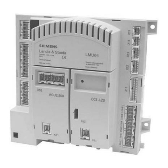
Siemens LMU54 Series Basic Documentation (171 pages)
Boiler Management Unit (BMU)
Brand:
Siemens
| Category:
Control Unit
| Size: 1.24 MB
Table of Contents
3
Table of Contents
10
Overview
10
Brief Description
10
System Concept
11
Features
11
Safety Functions
11
Supervision / Protective Functions for the Plant
11
Auxiliary Modules (Clip-In)
12
Dhw
12
Heating Circuit
12
System Application
12
Operation / Service
13
Parameterization
13
Mains Transformer
13
Other Features
13
Product Range
13
Field of Use
13
Target Market
14
Notes On Product Liability
14
Notes On Environmental Protection
14
Disposal Notes
15
Product Range Overview
17
Functions
17
Burner Control
17
Program Selection
17
Eeprom
17
Forced Intermittent Operation
17
Burner Control Program
18
Sequence Diagram
18
Capacity Range < 70 Kw
18
Capacity Range 70
19
Capacity Range > 120 Kw
19
Description of Sequence Diagrams
20
Sequence Times
20
Standby
20
Startup
22
Shutdown
22
Home Run
22
Special Cases (Deviations)
24
Lmu
24
Parameterization of Speed Feedback Signal
25
Fan Parameters Accessible Via QAA
26
The Different Capacity Ranges
27
Setting the Fan Parameters During Startup and Shutdown
28
Speed Readjustment
30
Selection of the Compensation Variants
30
Heating Circuits
32
Room Setpoint
34
Configuration of the Heating Circuits
35
DHW Circuit
37
Acquisition of Actual Values
37
Assignment of Analog Sensors
37
Temperatures
38
Display of Ionization Current
39
Supervisory Functions
39
Temperature Limiter Function
39
Flue Gas Temperature Supervision
39
Plausibility Check of Sensor
39
Function
40
Electronic (S)LT
40
Handling Faults
42
Flow Switch / Water Pressure Supervision
42
Function of Flow Switch
42
Function of Pressure Switch
42
Pressure Sensor
43
Static Supervision
44
Dynamic Supervision
45
Load Limitation
48
Speed Limitation
48
Limitation of Ionization Current
49
Boiler Control
49
Frost Protection for the Boiler
49
Controller Delay
49
Controller Delay Due to Parameterization
50
Controller Delay Due to SLT Criterion
50
Controller Configuration
50
Transfer of Setpoint / Actual Value
50
Determining the Controller Coefficients
51
Heat Output Limits
52
Boiler Temperature Control
52
2-Position Control
52
Minimum Boiler Pause Time
52
Boiler Cycling Protection
53
Dynamic Switch-Off Differential
54
Modulating Control, Conventional
55
Hydraulic System Management (HSM)
55
Frost Protection for the Plant
56
Consumer Management (CM)
56
Determining the Demands for Heat
56
Priorization of Demands for Heat
57
Determining the Temperature Demand
58
Temperature Limitation
59
Summer / Winter (S / W) Changeover
61
Electronically Controlled PWM Heating Circuit Pump
61
General
61
Introduction
61
Notes
61
Task of ∆T Control with PWM Pump
62
First Stage Maximum Limitation of the Flow Temperature
62
Second Stage ∆T Limitation
63
Third Stage ∆T Supervision
63
PWM Pump Control
63
H-Q Chart (Example)
64
Adaption of Modulating Pump to the Heating Plant
64
Parametes of the PWM Pump (OEM)
64
Preset Parameters
65
Activation of PWM Pump Via a Configuration Byte
66
Parameters of the PWM Pump (Installer)
66
Parameters for Temperatures
67
PID Controller Coefficients of Delta-T Supervision
67
Summary of All ∆T Parameters
68
Behavior in Different Operating Modes
68
Pump Overrun
68
Normal Operation (Heating Operation)
68
Reduced (Setback) Operation
68
Shutdown Mode
68
Heating Up Phase
69
DHW Operation
70
Heating Circuit Control
70
Attenuated Outside Temperature
71
Composite Outside Temperature
71
Type of Building Construction
72
Heating Curves
73
Generating the Demands for Heat
74
Time Switch
75
Room Thermostat
76
Combinations of RU and Room Thermostat / Time Switch
77
ECO Functions
77
S / W Changeover
77
Automatic 24-Hour Heating Limit
78
Quick Setback Constant (KON)
78
Generating the Temperature Demands
78
With Fixed Value Control or Emergency Operation
78
With Weather Compensation
79
Clip-In AGU2.500
79
Functions
79
General
79
Hydraulic Diagrams
79
Sensor Inputs (Analog Inputs)
79
Inputs / Outputs
80
Interfaces for the LMU
80
Sensor
80
Frost Protection
80
Overtemperature Protection
80
Mixing Circuits
80
Determining the Flow Temperature Setpoint
81
Pump Control
81
Pump Control with Pump Circuits
81
Pump Control with Mixing Circuits
81
Pump Overrun
81
Pump Kick
81
Mixing Valve Control
82
Clip-In Module OCI420
82
Functions
82
General
82
Inputs / Outputs
82
Interfaces to LMU
82
Connection of LMU
83
Automatic Changeover of Operating Mode
83
Giving Consideration to Heat Demand From the RVA
83
Locking and Forced Signals When Connecting to the LPB
83
External DHW Heating By ALBATROS Controllers
84
Type of Priority of DHW Heating
84
Multiboiler Plants with LMU (Cascade Applications)
85
Separate DHW Circuit in Cascade Applications
85
Operation with the RVA65
86
System Functions
86
Uniform System Time
86
Error / Diagnostic Messages From the LMU
88
Outside Sensor, Outside Temperature Sensor
88
Assignment of Address Numbers
88
Setting the LPB Device and Segment Address
89
Clip-In Function Module Agu2.51X
89
Functions
89
General
89
Outputs
89
Number of Available Outputs
90
Inputs
90
Digital Input
90
Analog Input
90
Predefined Setpoint (Temperature Demand)
91
Predefined Output
91
Sensor Input "Pressureless Header
93
DHW Control (BWR)
93
Boiler Temperature Setpoint During DHW Heating with Storage Tank
93
Systems
94
DHW Temperature Control
94
Compensation Variants
95
Position of Diverting Valve
95
Storage Tank Systems
96
Stratification Storage Tank
100
Instantaneous DHW System
100
Notes
100
Hydraulic Diagram
100
Operating Mode
100
Outlet Temperature Control (FS-DHW Is Closed)
100
Comfort Control (After FS-DHW Opening)
103
Aqua-Booster System
103
Hydraulic Diagram
103
Operating Mode
103
Outlet Temperature Control
103
Comfort Control
104
Legionella Function
105
Special Functions
105
Forced Signals
105
Parameterization
105
Via PC Tool ACS420 and OCI490
105
Via QAA73
106
Via AGU2.361 / AGU2.303
106
Programmable Input of the LMU
106
Modem Function
106
Warm Air Curtain Function
107
Programmable Output of the LMU
107
Status Output
107
Alarm Output
107
Operational Status Signal
108
Switching Off the External Transformer
108
Pump Output Second Heating Circuit
108
DHW Circulating Pump
108
Actuating Device with Warm Air Curtain Function Activated
108
Pump of Pressureless Header
108
Basic Function of Controller Clip-In Module
109
Actuating Device When Analog Signal Exceeds Threshold
109
Power Concept
110
Basic Diagram
110
Lmu
111
Connection Diagrams
111
Lmu
112
DHW Stepper Motor (Bipolar)
112
Agu2.104A109
113
Agu2.500A109
114
Agu2.500A209
115
Oci420A109
116
Oci420A209
117
Agu2.51X
118
Connecting Cable Between OCI490
119
Mounting, Electrical Installation and Service
119
Mounting (General)
119
Mounting the Lmu5X
119
Ignition Device
119
Terminals and Wiring
120
Testing By the Customer
121
Technical Data
121
Lmu
121
General
122
Electrical Connection Data
126
Cable Lengths (LMU
126
Connectors
127
Clip-In
127
Agu2.500
127
Outputs
127
Electrical Connections
127
Input
127
Agu2.51X
128
External Components
128
RAST5 Connectors
128
Mains Transformer
128
Fan with DC 24 V Motor
128
Fan with DC Motor Operating On Mains Voltage
129
Dimensions
129
Lmu5X
130
Lmu6X
131
AGU2.500A109 / Agu2.51Xa109
132
Agu2.500A209
133
Oci420A109
134
Oci420A209
135
Mounting Plate for Clip-In Module
136
Parameter List / Legend of Parameter Bit Fields LMU
136
Parameter List
136
Parameter List LMU
136
Temperatures
137
Switching Differentials
137
Controller Functions
138
Controller Times
138
Controller Coefficients
138
Pressures
139
Burner Control Fan
139
Burner Control Sequence
140
Burner Control Identification
140
Operating Data
140
MCI
140
Lpb
141
Lockout Position Storage
141
Phase Designations / Numbers
142
Legend of Parameter Bit Fields LMU
142
Controller Functions
145
Burner Control Program
147
Operating Modes
147
Lpb
148
Glossary of Abbreviations
148
Constants
148
Variables
149
Addendum: Hydraulic Diagrams BMU
149
Hydraulic Diagrams
149
Basic Diagrams
151
Pump Circuit Extensions Via AGU2.500
153
Mixing Circuit Extensions Via AGU2.500
156
Zone Extensions
162
Heat Generation Manager
166
Assignment of Hydraulic Diagrams to the Outputs of the LMU
Advertisement
Share and save
Advertisement
Related Products
Siemens LMU64 Series
Siemens LMV3 series
Siemens LMV51.040C2
Siemens LMV51.000C1
Siemens LMV52.240B1
Siemens LMV51.040B1
Siemens LMV51.100B1
Siemens LMV51.140B1
Siemens LMV51.200A1
Siemens LMV51.200A2
Siemens Categories
Control Unit
Controller
Measuring Instruments
Telephone
Cell Phone
More Siemens Manuals
×
Login
Sign In
OR
Sign in with Facebook
Sign in with Google
×
Upload manual
Upload from disk
Upload from URL