Sign In
Upload
Manuals
Brands
Siemens Manuals
Transmitter
7MF4912 series
Siemens 7MF4912 series Manuals
Manuals and User Guides for Siemens 7MF4912 series. We have
1
Siemens 7MF4912 series manual available for free PDF download: User Manual
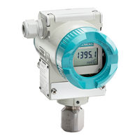
Siemens 7MF4912 series User Manual (211 pages)
SITRANS P DS III series Pressure, Differential Pressure, Flanged Level, and Absolute Pressure
Brand:
Siemens
| Category:
Transmitter
| Size: 4.6 MB
Table of Contents
Table of Contents
4
Contents
11
1 Introduction
13
Product Description
14
Gauge Construction, Pressure and Absolute Pressure Models
15
Differential Construction; Differential, Flow, and Absolute Models
16
Differential Pressure and Flow Models with H03 Option
17
Flanged Liquid Level Models
18
Traditional Application
19
Display
20
Configuration
21
Rating, Approval, and Tag Plates
21
2 Model 275 Universal Hart Communicator
22
Introduction
22
Communicator Connections
22
Model 275 Universal HART Communicator
23
HART Communicator Connections to a Transmitter Loop
24
Controls Overview
25
Liquid Crystal Display
25
Software-Defined Function Keys
25
Function Keys with Their Labels and Actions Performed
26
Action Keys
27
Alphanumeric and Shift Keys
28
Data Entry
28
Rapid Selection of Menu Options
28
Getting to Know the Communicator
29
Display Icons
29
Menu Structure
30
Reviewing Installed Devices
30
Communicator Firmware Device Descriptions, Rev. F2.2
31
Main Menu
32
Offline Menu
33
New Configuration
34
Saved Configuration
37
Online Menu
39
SITRANS P Online Menu Map
40
Generic Online Menu Map
41
Frequency Device Menu
42
Utility Menu
42
Configure Communicator
42
Listen for PC
43
Selftest
43
Simulation
43
Storage Location
43
System Information
43
Using the Quick Access Key
44
Adding Quick Access Key Options
45
Deleting Quick Access Key Options
46
3 Pre-Installation Test
47
Procedure
47
Test Equipment
48
Establishing Communication
49
Testing the Transmitter
49
Reviewing Configuration Data
50
Checking Transmitter Output
50
4 Installation
51
Equipment Delivery and Handling
51
Receipt of Shipment
51
Storage
51
Environmental Considerations
52
Pre-Installation Considerations and Calculations
52
Mechanical
52
Electrical
53
Impulse Piping for Absolute and Differential Models
54
Differential Flow Measurement Piping for Gas and Liquid
55
Differential Liquid Measurement Piping
56
Absolute or Gauge Pressure Measurement Piping
57
Steam Service, below the Line Mounting
58
Open and Closed Tank Level Measurement, Flange Mounted Transmitters
59
Transmitter Operating Mode and Network Type
60
Analog Mode
60
Point-To-Point Network (Analog Mode)
61
Procidia to Transmitter Connections (Analog Mode)
62
Model 353/354 to Transmitter Connections (Analog Mode)
63
Digital Mode
64
Power Supply Requirements
64
Multi-Drop Network (Digital Mode)
65
Point-To-Point Network
66
Multi-Drop Network
67
Determining Network (Loop) Length
67
Cable Capacitance
67
Maximum Cable Length Calculation
68
Network Junctions
69
Safety Barriers
69
Connection of Miscellaneous Hardware
70
Shielding and Grounding
71
Mechanical Installation
72
Pipe Mounting, Differential and Gauge Construction
72
Pipe Mounting, Gauge Construction
73
Direct Mounting to Process, Model 7MF4433 or 7MF4533
74
Flange Mounting, Model 7MF4633/7MF4912
75
Flange and Extension Dimensions
76
MECHANICAL INSTALLATION, All Models
77
Enclosure Rotation
77
Display Orientation
78
Conduit
79
Electrical Conduit and Cable Installation
79
Access to Transmitter Terminal Compartment
80
Cables
80
Electrical Installation
81
Network Conductor Terminations
82
Hazardous Area Installation
83
5 Post-Installation Test
84
Test Equipment
84
Installation Review
84
Equipment Connection
85
Verification
86
Communication Test
86
Transmitter Selftest
86
Loop Test
87
Transmitter Zero and Shutoff Valve Manipulation
88
Absolute Pressure
88
Measuring Gases
89
Measuring Vapor and Liquid
90
Differential Pressure and Flow
91
Measuring Gases
91
Measuring Liquids
92
Measuring Liquids
93
Measuring Vapor
94
6 On-Line Configuration and Operation
96
Local Operation and Display
96
Digital Display
96
Numeric Display
97
Unit/Bargraph Display
98
Error Message
98
Output Signal Range
98
Mode Display
99
Local Operation with the Magnetic Pushbuttons
100
Parameters Accessible Using the Magnetic Pushbuttons
101
Cancel Pushbutton Disable and Write Protection
102
Set/Adjust Zero and Full Scale
102
Theoretical Relationships
102
Practical Applications
104
Blind Setting of Zero and Full Scale
105
Electric Damping
105
Theoretical Relationships
105
Practical Applications
106
Zero Adjustment (Position Correction)
107
Zero-Point Alignment at Absolute Pressure
107
Failure Current
108
Fixed Current Output
108
Flow Measurement (Differential Pressure Only)
109
Pushbutton and Function Disable
109
Switch Point of the Square Root Characteristic
110
Select Measured Value to be Displayed
111
Select the Displayed Input Pressure Engineering Unit
111
Displayable Engineering Units
112
Local Operation Without a Display or with Activated Keylock
113
Set Zero and Full Scale
113
Remote Configuration and Operation by Hart
115
Process Data
115
Blind Setting of Zero and Full Scale
116
Setting Zero and Full Scale
116
Zero Adjustment for Position Correction
116
Electric Damping
117
Fast Measured Value Acquisition (Fast Response Mode)
117
Fault Current
118
Fixed Current Output
118
Disabling the Transmitter Magnetic Pushbuttons and Write Protection
119
Display/Bargraph
120
Measured Value Display
120
Select Pressure Engineering Units
120
Sensor Trim
121
Trimming the Lower Sensor Adjustment Point
121
Trimming the Upper Sensor Adjustment Point
122
D/A Trim
123
Transmitter Current Adjustment
123
Factory Calibration (Manufacturer Trims)
124
Device Information
125
Diagnostic Functions
125
Flow Measurement (Differential Pressure)
125
Calibration Timer and Service Timer
126
Operating Hours Counter
126
Min/Max Pointer
127
Monitoring the Saturation Current
127
Simulation
128
Self Test and Master Reset
129
7 Calibration and Maintenance
130
Calibration
131
Preventive Maintenance
132
Transmitter Exterior Inspection
132
Transmitter Exterior Cleaning
132
Transmitter Enclosure Interior Inspection
133
Transmitter Calibration
133
Impulse Piping
133
Troubleshooting
134
Analog Output
134
Digital Output (Communication)
137
Assembly Removal and Replacement
138
Display Assembly
140
Replacing the Electronics Module
141
Measuring Cell Assembly Removal and Replacement
142
Terminal Board Assembly Removal and Replacement
145
Non-Field-Replaceable Items
145
Transmitter Replacement
146
Maintenance Records
147
Recommended Spare and Replacement Parts
147
COMPATIBILITY, Revision Numbers
148
8 Circuit Description
149
Overall Operation
150
Pressure
150
Differential Pressure and Flow
151
Flanged Level
151
Absolute Pressure (Differential Construction)
152
Absolute Pressure (Gauge Construction)
152
Communication Format
153
9 Model Designations and Specifications
154
Model Designations
154
Model 7MF4033, Model Designation
155
Model 7MF4233, Model Designation
157
Model 7MF4333, Model Designation
159
Model 7MF4433, Model Designation
161
Model 7MF4533, Model Designation
163
Models 7MF4633 and 7MF4912, Model Designation
165
Accessories
173
Specifications
174
Measuring Spans and Overload Limits
182
Network Topology
188
Two-Wire Cable
188
HAZARDOUS AREA Classifications
188
CSA Hazardous Locations Precautions
189
10 Glossary
193
11 Appendix A - Online Configuration Map
196
Online Configuration Map, Part 1 of 2
197
Online Configuration Map, Part 2 of 2
198
12 Appendix B - Hazardous Area Installation
199
Control Drawing
200
Control Drawing
201
13 Appendix C - Elevation and Suppression Corrections
202
How Adjustment Is Made
202
Elevation Calculation Example
203
Recommended Method
204
Advertisement
Advertisement
Related Products
Siemens 7MF4033 series
Siemens 7MF4233 series
Siemens 7MF4533 series
Siemens 7MF4333 series
Siemens 7MF4433
Siemens 7MF4812
Siemens 7MF4.33 Series
Siemens 7MF4.34 Series
Siemens 7MF4.35 Series
Siemens 7MF4010
Siemens Categories
Industrial Equipment
Controller
Control Unit
Oven
Washer
More Siemens Manuals
Login
Sign In
OR
Sign in with Facebook
Sign in with Google
Upload manual
Upload from disk
Upload from URL