Sign In
Upload
Manuals
Brands
SICK Manuals
Industrial Equipment
VMS5100
SICK VMS5100 Manuals
Manuals and User Guides for SICK VMS5100. We have
3
SICK VMS5100 manuals available for free PDF download: Operating Instructions Manual, Addendum To Operating Instructions
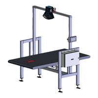
SICK VMS5100 Operating Instructions Manual (124 pages)
Track and trace systems
Brand:
SICK
| Category:
Measuring Instruments
| Size: 8 MB
Table of Contents
Table of Contents
3
1 About this Document
6
Limitation of Liability
6
Purpose of this Document
6
Target Groups
6
Further Information
7
Other Relevant Technical Documentation/Information
7
Document Conventions
7
2 Safety Information
8
Intended Use
8
General Safety Notes
9
Requirements for the Qualification of Personnel
9
Sources of Hazard
10
Protective Devices
10
Warranty
10
Rohs Directive
11
Safety Conventions
11
Warning Symbols on the System Components
12
Mandatory Symbols
12
3 System Description
13
Scope of Delivery
13
System Components
14
Lms4X21 2D-Lidar Sensor
16
Incremental Encoder
17
Photoelectric Retro-Reflective Sensor Trigger (Optional)
17
Cabinet
18
Expanding the System with a Reading Station
20
Triggering the Recording of Measured Values
21
Operating Modes
23
Singulated" Operating Mode (Cubic Only)
23
Singulated" Operating Mode with Additional "Touching/Side-By-Side", "Singulation Verification" (SIV) Function
24
Touching/Side-By-Side" Operating Mode (Cubic Only)
28
Determining Measurement Results and Outputting Data
31
Recording of Measured Values and 3D Modeling
31
Evaluating the 3D Model in each Operating Mode
31
Data Output
33
Additional Function
35
Nominal Operating Conditions
36
Nominal Value Conditions for the "Singulated" and "Touching/Side-By-Side"Operating Modes (Cubic Only)
36
Dynamic Scale Value Switchover
39
Legal for Trade Operation
41
Information Labels
41
Security Seal
47
Alibi Memory and Firmware
53
LFT Display
56
Test Instructions for Market Surveillance
59
System Requirements for Legal for Trade Operation
63
Requirements on the Ambient Conditions
63
Requirements on the Conveying Equipment
63
Mounting Requirements
64
Object Requirements
66
4 Mounting
68
Mounting the 2D Lidar Sensor
68
Mounting the Incremental Encoder
70
Mounting the Photoelectric Retro-Reflective Sensor Trigger (Optional)
71
Mounting the Cabinet
72
5 Electrical Installation
73
Connection Overview
74
Cabinet Without Ethernet Switch
74
Cabinet with Ethernet Switch
75
Connection to the Voltage Supply
76
Connection for the Ethernet Switch (Set up at the Factory) - Cabinet with Ethernet Switch Only
77
Connection of the 2D Lidar Sensor
78
Cabinet Without Ethernet Switch
78
Cabinet with Ethernet Switch
79
Connection for the LFT Display (Set up at the Factory)
80
Cabinet Without Ethernet Switch
80
Cabinet with Ethernet Switch
81
Connecting the Incremental Encoder
82
Connection for the Photoelectric Retro-Reflective Sensor Trigger (Optional)
83
Connection for the Customer Interface
84
6 Commissioning
85
Switching on the System
85
Configuring the System with SOPAS
86
Connecting the Configuration PC
86
Installing SOPAS
87
Assigning IP Addresses
88
Opening the Configuration Interface
94
Logging into the Device
96
Saving the Parameters Permanently
96
7 Maintenance and Repair
97
Monitoring and Cleaning Work
98
Control Measurements
98
Visual Control
98
Cleaning the 2D Lidar Sensor
99
Cleaning the Deflector Mirror
100
Checking the Incremental Encoder Components
101
Cleaning the Photoelectric Retro-Reflective Sensor
101
Cleaning the Cabinet
102
Replacing Components
103
Replacing the 2D Lidar Sensor
103
Replacing the Deflector Mirror
105
Replacing the Incremental Encoder Components
106
Replacing the Photoelectric Retro-Reflective Sensor (Optional)
107
8 Fault Diagnosis
108
Fault Indications of the Components
108
Fault Indication on the Lms4X21
108
SIM2000 Fault Indication
109
Fault Indication on the Photoelectric Retro-Reflective Sensor Trigger
110
Checks on the SIM2000
111
Checking the Triggering
111
Checking the Incremental Encoder
112
Checking the CAN Cabling
113
Detailed Fault Analysis
114
9 Technical Data
115
Data Sheet
115
Dimensional Drawings
117
Dimensional Drawings for the 2D Lidar Sensor
117
Dimensional Drawings for the Cabinet
118
Compliance with EU Directives
119
10 Disposal
120
Advertisement
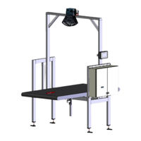
SICK VMS5100 Addendum To Operating Instructions (122 pages)
Track and trace system
Brand:
SICK
| Category:
Industrial Equipment
| Size: 9 MB
Table of Contents
Table of Contents
3
About this Document
6
Limitation of Liability
6
Purpose of this Document
6
Target Groups
6
Further Information
7
Other Relevant Technical Documentation/Information
7
Document Conventions
7
For Your Safety
8
Intended Use
8
General Safety Notes
9
Requirements for the Qualification of Personnel
9
Sources of Danger
10
Protective Devices
10
Warranty
10
Rohs Directive
11
Safety Conventions
11
Warning Symbols on the System Components
12
Mandatory Symbols
12
System Description
13
Scope of Delivery
13
System Components
14
Lms4X21 2D Lidar Sensor
16
Incremental Encoder
17
Trigger Photoelectric Sensor (Optional)
18
Cabinet
19
Expanding the System with a Reading Station
22
Triggering the Recording of Measured Values
23
Operating Modes
25
Singulated" Operating Mode (Cubic Only)
25
Singulated" Operating Mode with Additional "Touching/Side-By-Side", "Singulation Verification" (SIV) Function
26
Touching/Side-By-Side" Operating Mode (Cubic Only)
30
Determining Measurement Results and Outputting Data
33
Recording of Measured Values and 3D Modeling
33
Evaluating the 3D Model in each Operating Mode
33
Data Output
35
Additional Function
37
Nominal Operating Conditions
38
Nominal Value Conditions for the "Singulated" and "Touching/Side-By-Side"Operating Modes (Cubic Only)
38
Dynamic Scale Value Switchover
41
Legal for Trade Operation
43
Information Labels
43
Security Seal
49
Alibi Memory and Firmware
54
LFT Display
57
Test Instructions for Market Surveillance
60
System Requirements for Legal for Trade Operation
64
Requirements on the Ambient Conditions
64
Requirements on the Conveying Equipment
64
Mounting Requirements
65
Object Requirements
67
Mounting
69
Mounting the 2D Lidar Sensor
69
Mounting the Incremental Encoder
71
Mounting the Photoelectric Sensor Trigger (Optional)
72
Mounting the Cabinet
73
Electrical Installation
74
Connection Overview
75
Cabinet Without LFT Ethernet Switch
75
Cabinet with LFT Ethernet Switch
76
Connecting the Voltage Supply
77
Connection for LFT Ethernet Switch (Set up at the Factory)
78
Connection of the 2D Lidar Sensor
79
Connection of the 2D Lidar Sensor to the SIM2000-2 Prime Controller
79
Connection of the 2D Lidar Sensor on LFT Ethernet Switch
80
Connection for the LFT Display (Set up at the Factory)
81
Connection of LFT Display on the Controller
81
Connection of the LFT Display on LFT Ethernet Switch
82
Connection of the Incremental Encoder
83
Connection for the Photoelectric Sensor Trigger (Optional)
84
Connecting the Customer Interface
85
Commissioning
86
Switching on the System
86
Configuring the System with SOPAS
87
Connecting the Configuration PC
87
Installing SOPAS
88
Assigning IP Addresses
89
Opening the Configuration Interface
95
Logging on to Device
97
Saving the Parameters Permanently
97
Maintenance and Repair
98
Monitoring and Cleaning Work
99
Control Measurements
99
Visual Inspection
99
Cleaning the 2D Lidar Sensor
100
Cleaning the Deflector Mirror
101
Checking the Incremental Encoder Components
102
Cleaning the Photoelectric Retro-Reflective Sensor
102
Cleaning the Cabinet
103
Replacing Components
104
Replacing the 2D Lidar Sensor
104
Replacing the Deflector Mirror
106
Replacing the Incremental Encoder Components
107
Replacing the Photoelectric Retro-Reflective Sensor (Optional)
108
Replacing the Battery in the SIM2000-2 Prime Controller
109
Fault Diagnosis
110
Fault Indications of the Components
110
Fault Indication on the Lms4X21
110
SIM2000 Fault Indication
111
Fault Indication on the Photoelectric Sensor Trigger
112
Checks on the SIM2000
113
Checking the Triggering
113
Checking the Incremental Encoder
114
Checking the CAN Cabling
115
Detailed Fault Analysis
116
Technical Data
117
Data Sheet
117
Dimensional Drawings
119
Dimensional Drawings for the 2D Lidar Sensor
119
Dimensional Drawings for the Cabinet
120
Compliance with EU Directives
121
Disposal
122
SICK VMS5100 Operating Instructions Manual (108 pages)
Track and trace systems
Brand:
SICK
| Category:
Industrial Equipment
| Size: 6 MB
Table of Contents
Table of Contents
3
1 About this Document
6
Limitation of Liability
6
Purpose of this Document
6
Target Groups
6
Further Information
7
Other Relevant Technical Documentation/Information
7
Document Conventions
7
2 Important Safety Notes
8
Safety Conventions
8
Supplementary Safety Note
8
Requirements for the Qualification of Personnel
8
Intended Use
9
Rohs Directive
9
Safety Notes
10
3 System Description
11
Scope of Delivery
11
System Components
12
Volume Measurement Device
13
Incremental Encoder
14
Photoelectric Retro-Reflective Sensor Trigger
15
Cabinet with SIM2000
16
Expanding the System with a Reading Station
17
Triggering the Recording of Measured Values
18
Operating Modes
20
Singulated' Operating Mode (Cubic Only)
20
Singulated" Operating Mode with Additional "Singulation Verification" (SIV) Function
21
Touching/Side-By-Side" Operating Mode (Cubic Only)
25
Determining Measurement Results and Outputting Data
28
Recording of Measured Values and 3D Modeling
28
Evaluating the 3D Model in each Operating Mode
28
Data Output
30
Additional Function
32
Nominal Value Conditions
33
Nominal Value Conditions for the "Singulated" and "Touching/Side-By-Side"Operating Modes (Cubic Only)
33
Dynamic Scale Value Switchover
36
System Requirements
38
Required Interfaces
38
Requirements at the Operation Site
38
Object Requirements
38
Conveying Equipment Requirements
39
Mounting Requirements
40
Officially Verifiable Operation
43
Information Labels
43
Security Seal
48
Alibi Memory and Firmware
53
LFT Display
55
Test Instructions for Market Surveillance
58
4 Mounting
61
Mounting the Volume Measurement Device
61
Mounting the Incremental Encoder
63
Mounting the Photoelectric Retro-Reflective Sensor and Reflector (Optional)
64
Mounting the Cabinet
64
5 Electrical Installation
65
Connection Overview
66
Connecting to the Voltage Supply
67
Connecting the Volume Measurement Device
68
Connecting the LFT Display
69
Connecting the Incremental Encoder
70
Connection for the Photoelectric Retro-Reflective Sensor (Optional)
71
Connecting to the Customer Interface
72
6 Commissioning
73
Switching on the System
73
Configuring the System with SOPAS
74
Installing SOPAS ET
74
Connecting the Configuration PC
74
Installing SOPAS
75
Assigning IP Addresses
76
Opening the Configuration Interface
81
Logging into the Device
82
Saving the Parameters Permanently
83
7 Maintenance and Repair
84
Monitoring and Cleaning Work
85
Control Measurements
85
Visual Inspection
85
Cleaning the Volume Measurement Device
86
Checking the Incremental Encoder Components
87
Cleaning the Photoelectric Retro-Reflective Sensor
87
Cleaning the Cabinet
88
Replacing Components
89
Replacing the Volume Measuring Device
89
Replacing the Incremental Encoder Components
91
Replacing the Photoelectric Retro-Reflective Sensor (Optional)
92
8 Fault Diagnosis
93
Fault Indications of the Components
93
Fault Indication on the Lms4Xxx
93
SIM2000 Fault Indication
94
Photoelectric Sensor Fault Indication
95
Checks on the SIM2000
96
Checking the Triggering
96
Checking the Incremental Encoder
97
Checking the CAN Cabling
98
Detailed Fault Analysis
99
9 Annex
100
Technical Data
100
Data Sheet
100
Dimensional Drawings for the Volume Measurement Device
102
Dimensional Drawings for the SIC2000-2100
102
Compliance with EU Directives
103
10 Disposal
104
Advertisement
Advertisement
Related Products
SICK VMS4100
SICK VMS4300
SICK VMS5300
SICK V4000
SICK VMS4200
SICK VMS5200
SICK VMS6200
SICK VMS4400 CV
SICK VMS410
SICK VMS510
SICK Categories
Accessories
Security Sensors
Measuring Instruments
Scanner
Barcode Reader
More SICK Manuals
Login
Sign In
OR
Sign in with Facebook
Sign in with Google
Upload manual
Upload from disk
Upload from URL