Sign In
Upload
Manuals
Brands
SICK Manuals
Measuring Instruments
VMS6200
SICK VMS6200 Manuals
Manuals and User Guides for SICK VMS6200. We have
2
SICK VMS6200 manuals available for free PDF download: Operating Instructions Manual
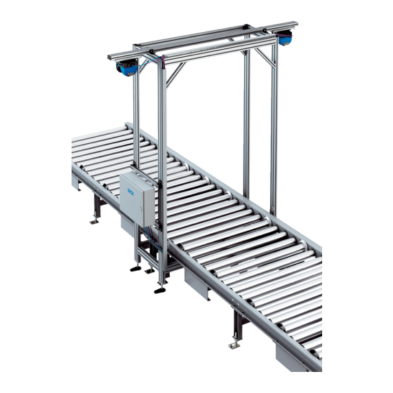
SICK VMS6200 Operating Instructions Manual (84 pages)
Track and trace systems
Brand:
SICK
| Category:
Measuring Instruments
| Size: 3 MB
Table of Contents
Table of Contents
3
1 About this Document
5
Limitation of Liability
5
Purpose of this Document
5
Target Groups
5
Further Information
6
Other Relevant Technical Documentation/Information
6
Document Conventions
6
2 Safety Information
7
Intended Use
7
General Safety Notes
7
Requirements for the Qualification of Personnel
8
Protective Devices
8
System Warranty
8
Rohs Directive
8
Safety Conventions
9
Warning Symbols on the System Components
10
Mandatory Symbols
10
Safety Notes
11
3 System Description
12
Scope of Delivery
12
System Components
13
LMS500 2D Lidar Sensors
14
Trigger Photoelectric Sensor
15
Incremental Encoder
16
Cabinet
17
Operating Principle
18
Automated Operating Mode
18
Recording of Measured Values and Data Processing
20
Data Output
21
Expanding the System with a Reading and Weighing Station
22
System Requirements
23
Requirements on the Ambient Conditions
23
Requirements on the Conveying Equipment
23
Object Requirements
24
Mounting Requirements
25
4 Mounting
27
Mounting Volume Measurement Devices
27
Mounting Components
28
Fastening the Mounting Plate to the Frame
29
Screwing the Volume Measurement Device Plus Adapter Plate to the Mounting Plate
29
Mounting the Photoelectric Retro-Reflective Sensor
30
Mounting the Incremental Encoder
30
Mounting the Cabinet
31
5 Electrical Installation
32
Connection Overview
33
Connection to the Voltage Supply
34
Factory Connections
35
Connecting the Volume Measurement Devices
36
Connection for the Photoelectric Retro-Reflective Sensor
37
Connecting the Incremental Encoder
38
Connecting to the Customer Interface
39
6 Commissioning
40
Switching on the System
40
Checking the Operational Readiness of the System Components
41
Configuring the System with SOPAS
42
Installing SOPAS ET
42
Installing SOPAS
43
Assigning IP Addresses
44
Opening the Configuration Interface
50
Configuring the LMS500 and VMC800
51
Configuring Basic Settings for the MSC800
52
Checking System Readiness
52
Testing the Configuration
53
Optimizing the Measurement Results
55
Saving the Configuration
56
7 Maintenance and Repair
57
Monitoring and Cleaning Work
58
Control Measurements
58
Visual Control
58
Cleaning the Volume Measurement Devices
59
Cleaning the Photoelectric Retro-Reflective Sensor
60
Cleaning the Components of the Incremental Encoder
60
Cleaning the Cabinet
61
Replacing Components
62
General Notes
62
Replacing the Volume Measuring Device
63
Replacing the MSC800
65
Replacing the VMC800
67
Replacing the Photoelectric Retro-Reflective Sensor
69
Replacing the Components of the Incremental Encoder
70
8 Fault Diagnosis
71
Fault Indications of the Components
71
Fault Indication on the LMS500
71
Fault Indication on the MSC800
72
Fault Indication on the Photoelectric Retro-Reflective Sensor
73
Fault Indication During Operation
74
Checking the Triggering
74
Checking the Incremental Encoder
75
Checking the CAN Cabling
76
Detailed Fault Analysis
77
9 Technical Data
78
10 Disposal
80
Advertisement
SICK VMS6200 Operating Instructions Manual (30 pages)
Track and trace system
Brand:
SICK
| Category:
GPS
| Size: 3 MB
Table of Contents
Table of Contents
3
About this Document
5
Information on the Operating Instructions
5
Scope
5
Target Group
5
Further Information
5
Related Applicable Documents
5
Symbols and Document Conventions
6
Safety Information
7
Basic Safety Notes
7
Intended Use
8
Improper Use
8
Qualification of Personnel
9
Product Description
10
Scope of Delivery
10
Product Identification
10
Product Identification Via the SICK Product ID
10
Overview of the Product
11
Product Characteristics
12
Design and Function
12
System Components
14
Project Planning
18
Requirements on the Conveyor System
18
Requirements on the Measuring Objects
18
Requirements on the Transport of Objects on the Conveyor System
19
Integration into the Network
20
Configuration
21
Configuration of the IP Addresses
21
Operation
22
Switching on the System
22
Maintenance
23
Regular Maintenance Work
23
Replacing the LMS500 Sensor
23
Replacing the Photoelectric Sensor
25
Replacing the Incremental Encoder
26
Replacing Components in the Control Cabinet
26
Troubleshooting
27
Fault Indications of the Components
27
Advertisement
Related Products
SICK VMS4400 CV
SICK VMS410
SICK VMS510
SICK VICOTEC450
SICK VMS4200
SICK VMS5200
SICK VMS4100
SICK VMS5100
SICK VMS4300
SICK VMS5300
SICK Categories
Accessories
Security Sensors
Measuring Instruments
Scanner
Barcode Reader
More SICK Manuals
Login
Sign In
OR
Sign in with Facebook
Sign in with Google
Upload manual
Upload from disk
Upload from URL