Sign In
Upload
Manuals
Brands
SICK Manuals
Measuring Instruments
VMS410
SICK VMS410 Volume Measurement System Manuals
Manuals and User Guides for SICK VMS410 Volume Measurement System. We have
1
SICK VMS410 Volume Measurement System manual available for free PDF download: Operating Instructions Manual
SICK VMS410 Operating Instructions Manual (78 pages)
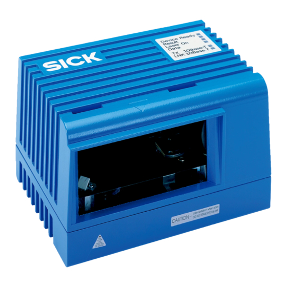
Volume Measurement System
Brand:
SICK
| Category:
Measuring Instruments
| Size: 3 MB
Table of Contents
Table of Contents
5
About this Document
11
Function of this Document
11
Target Group
11
Mounting, Electrical Installation, Maintenance and Replacement
11
Commissioning, Operation and Configuration
11
Depth of Information
11
Symbology Used
12
For Your Safety
13
Authorised Personnel
13
Mounting and Maintenance
13
Electrical Installation and Replacement
13
Commissioning, Operation and Configuration
13
Applications of the Device
13
Correct Use
14
General Safety Notes and Protective Measures
14
Quick Stop and Quick Restart
16
Switch off VMS
16
Switch VMS Back on
16
Environmental Protection
17
Power Consumption
17
Disposal after Final De-Commissioning
17
Product Description
18
Delivery
18
Special Features
18
Operating Principle of the Device
18
Operating Principle VMS
18
Measuring Modes
19
Evaluation of the RIS Values
22
Camera Focusing
22
Increment Settings
22
Planning
23
System Requirements for the VMS Volume Measurement System
23
Requirements on the Conveyor System
23
Object Specifications
24
Mounting Requirements
24
Tab. 1: Minimum and Maximum Object Dimensions
24
Tab. 2: Minimum Distance between the Top Edge of the Object and the Measurement Zero Point
25
Standardisation of the VMS510
26
Tab. 3: Certified, Measurable Object Sizes at 1.2 M/S (236.22 Ft/Min)
26
Tab. 4: Certified, Measurable Object Sizes at 2 M/S (393.7 Ft/Min)
26
Scale Intervals of the VMS
28
Dynamic Scale Intervals
28
Tab. 5: Typical Scale Intervals
28
Status Indicators
29
Data Interfaces Specification
29
Terminal Interface
29
Tab. 6: Significance of the Leds
29
Host Interface
30
Tab. 7: Frame for the Messages on the Host Interface
30
Tab. 8: Example Rounded Measured Results
31
Ethernet Interface
32
CAN Interface
32
Mounting
33
Overview of the Mounting Steps
33
Preparations for Mounting
33
Components to be Mounted
33
Place Material at Hand
33
Mounting Accessories
33
Mounting the VMD
34
Dismounting the System
34
Electrical Installation
35
Overview of the Installation Steps
35
Electrical Connections and Cables
35
Tab. 9: Function of the Electric Connections of the VMS
35
Pin Assignment of the Connections
36
Ethernet" Connection
36
System" Connection
36
Tab. 10: Pin Assignment of the "Ethernet" Connection
36
Tab. 11: Pin Assignment of the "System" Connection
36
I/O" Connection
37
Tab. 12: Pin Assignment of the "I/O" Connection
37
Serial" Connection
38
Tab. 13: Pin Assignment of the "Serial" Connection
38
Connection Via the Plug Cover
39
Performing Electrical Installation
39
Overview of the Connection Steps
39
Equipment
39
Connecting the Voltage Supply
39
Connecting the PC
40
Commissioning
41
Configuration and Adjustment
42
Preparing the Configuration and Adjustment
42
Mechanically Adjusting VMD
43
Adjustment above a Conveyor System
43
Adjustment of the Angle
44
Adjustment of the Angle
45
Define the Coordinates and the Angle Gamma Using the Installation Setup
46
Defining the Angle , the y and the Z Coordinates
46
Defining the Transporting Surface
46
Defining the y Coordinate
47
Applying the Parameters
48
Defining the Scan Settings, Encoder Settings and the Measured Data Message in SOPAS
48
Configuring the Scan Settings
48
Encoder Settings
48
Measured Data Message
49
Testing of the Configuration
49
Display of the Measurement Results
49
VMS Results List
49
Noise Statistics
49
Scan View
49
3D Object View
49
Maintenance
50
Maintenance During Operation
50
Disposal
51
Replacement of a System or Replacement of Components
51
Troubleshooting
52
In the Event of Faults or Errors
52
Error on Beam Generation
52
Detailed Error Analysis
52
Query System Status
52
Logging Data During Operation
52
Technical Specifications
53
Data Sheet VMS410/510 Volume Measurement System
53
Tab. 14: VMS Data Sheet
53
Dimensional Drawings
55
Dimensional Drawing VMD Volume Measurement System
55
Dimensional Drawing Mounting Kit for VMD
56
Annex
57
Overview of the Annexes
57
Control Messages Reference
57
Tab. 15: Syntax Error or Logical Errors
57
Object Start
58
Object End
58
Heartbeat
58
Stand-By
59
Measuring Mode
59
Measured Data Message Reference
61
Basic Measured Data Message (Metric Values)
61
Basic Measured Data Message (Values in Inch)
62
Basic Measured Data Message 2 (Metric Values)
63
Basic Measured Data Message 2 (Values in Inch)
64
Extended Measured Data Message (Metric Values)
66
Extended Measured Data Message (Values in Inch)
67
Extended Measured Data Message 2 (Metric Values)
68
Extended Measured Data Message 2 (Values in Inch)
69
Ordering Information
70
Available Systems
70
Accessories/Spare Parts
70
Tab. 16: Available Systems
70
Tab. 17: General Accessories
70
Tab. 18: Interface Sets
70
Tab. 19: Plug Cover Sets
71
Tab. 20: Accessories for Plug Covers
71
Tab. 21: Spare Parts Measuring Head
71
Glossary
72
Illustration Containing the EC Declaration of Conformity
74
Illustration of the MID Conformity Certificate
75
Illustration of the OIML Conformity Certificate
76
Advertisement
Advertisement
Related Products
SICK VMS6200
SICK VMS4400 CV
SICK VMS510
SICK VICOTEC450
SICK VMS4200
SICK VMS5200
SICK VMS4100
SICK VMS5100
SICK VMS4300
SICK VMS5300
SICK Categories
Accessories
Security Sensors
Measuring Instruments
Scanner
Barcode Reader
More SICK Manuals
Login
Sign In
OR
Sign in with Facebook
Sign in with Google
Upload manual
Upload from disk
Upload from URL