Sign In
Upload
Manuals
Brands
SICK Manuals
Gateway
Flexi Classic
SICK Flexi Classic Manuals
Manuals and User Guides for SICK Flexi Classic. We have
4
SICK Flexi Classic manuals available for free PDF download: Operating Instructions Manual
SICK Flexi Classic Operating Instructions Manual (156 pages)
Brand:
SICK
| Category:
Gateway
| Size: 4 MB
Table of Contents
Table of Contents
3
1 About this Document
7
Function of this Document
7
Target Group
7
Information Depth
7
Scope
8
Symbols Used
8
2 On Safety
9
Qualified Safety Personnel
9
Correct Use
9
Environmental Protection
10
Disposal
10
Separation of Materials
10
System Information Transmitted by the Modules
11
Status Information of All Flexi Classic Gateways (System Bytes)
12
Dig-Out
12
Req-ID
12
CRC1 and CRC2
13
Bas1
14
Bas2
14
Bas3
15
Bas4
15
Rsp-ID
15
Yt28/2016
15
B1-B10 (Req-ID 1-13/2133)
16
B1-B10 (Req-ID 255)
16
Med
16
Mqd
17
Mkd1
18
Mkd2
18
Mfd
19
Mfclass1-Mfcode2
19
Mod-ID
24
SW-VERSION_H and SW-VERSION_L
25
Function
25
Konf
26
CRC_H CODE and CRC_L CODE
26
DIAG-VERSION_H and DIAG-VERSION_L
26
System Interface Status (Only UE410-EN3)
26
4 PROFIBUS DP Gateway
27
Interfaces and Operation
27
Controls and Status Indicators
27
Application Diagnostic Outputs UE410-PRO
28
Plug Assignment
28
Bus Cable
28
Cable Parameters
29
Data Transmission Rate
29
Planning
30
GSD File
30
Documenting with PROFIBUS-DP Master Simulator
31
Diagnostics Data UE410-PRO
31
5 Canopen Gateway
32
Interfaces and Operation
32
Control and Status Indicators
32
Application Diagnostic Outputs UE410-CAN
33
Plug Assignment
34
Bus Cable
34
Planning
35
EDS File
35
Pcs
35
Format of Diagnostics Data
35
Txpdo1
36
Txpdo2
36
Txpdo3
37
Txpdo4
37
Rxpdo1
38
NMT Network Management
38
Pre-Operational
38
Operational
38
Prepared/Stopped
38
Reset Node
38
Reset Communication
39
Sync
39
Node-Guarding
39
Emergency
40
SDO Communication
40
SDO Download Expedited (Write SDO)
40
SDO Upload Expedited (Read SDO)
41
Object List SDO
41
Configuration Objects
42
Input/Output Objects
43
Module List Objects
43
Mapping/Communication Parameter Objects
44
Flexi-Classic-ERROR List Object
45
Status Objects
46
6 Devicenet Gateway
47
Interfaces and Operation
47
Characteristics of the Devicenet Implementation
47
Controls and Status Indicators
47
Application Diagnostic Outputs UE410-DEV
48
Plug Assignment
49
Bus Cable
49
Planning
50
EDS File
50
Diagnostics Data UE410-DEV
50
7 Modbus/Tcp Ethernet Gateway
51
Interfaces and Operation
51
Basic Configuration - Assigning an IP Address
52
Configuration of the Interface to the PLC - How the Data Are Transferred
54
Operating Modes in the Transfer Mode RX (to PLC)
56
Operating Modes in the Transfer Mode Tx (from PLC)
58
Modbus Commands and Error Messages
58
Configuration of the Gateway - Which Data Are Transferred
59
Status of the Interface to the PLC
61
Resetting to Factory Settings
64
Troubleshooting
65
Description of the Data Sets
67
Data Sets 1-5
67
Data Set 6, Can be Compiled by the User
69
8 Ethernet TCP/IP Gateway
71
Interfaces and Operation
71
Basic Configuration - Assigning an IP Address
72
Configuration of the TCP/IP Interface - Who Establishes the Connection
74
Data Transfer Method - How the Data Are Transferred
76
General Telegram Structure
76
Error Response to Invalid Messages
77
Auto Update Mode
77
Polling Mode
80
Ethernet TCP/IP Interface Status and Statistics
83
Resetting to Factory Settings
85
Troubleshooting
86
Description of the Data Sets
88
Data Sets 1-5
88
Data Set 6, Can be Compiled by the User
90
9 Ethernet/Ip Gateway
92
Interfaces and Operation
92
Basic Configuration - Assigning an IP Address
93
Device Name
94
Configuration of the Interface to the PLC - How the Data Are Transferred
95
Operating Modes in the Transfer Mode Rx (to PLC)
98
Operating Modes in the Transfer Mode Tx (from PLC)
99
Configuration of the Gateway - Which Data Are Transferred
100
Status of the Interface to the PLC
102
Ethernet/Ip Objects
105
Full Data Set Transfer Object
105
Individual Data Set Transfer Object (73Hex - One Instance Per Data Set)
106
Discrete Output Point Object Definition (09Hex - 4 Instances; One Instance Per Digital Output)
113
Resetting to Factory Settings
115
Troubleshooting
116
9.10 Description of the Data Sets
118
Data Sets 1-5
118
Data Set 6, Can be Compiled by the User
120
SICK AG • Industrial Safety Systems • Germany • All Rights Reserved
120
10 PROFINET IO Gateway
122
10.1 Interfaces and Operation
122
10.2 Basic Configuration - Assigning an IP Address
123
Web Server Based
123
PROFINET IO Conform
125
PROFINET Configuration of the Gateway - How the Data Are Transferred
125
STEP 1 - Install the Generic Station Description File (GSD File)
125
STEP 2 - Add the Gateway to the Project
126
STEP 3 - Configure the Properties of the Gateway
126
STEP 4 - Assign the Device Name
127
PROFINET Configuration of the Gateway - Which Data Are Transferred
129
Cyclic Data
129
Acyclic Data - Record Read
130
Alarms
136
10.5 Status of the Interfaces
137
Status of the Interface to the PLC
137
Status of the Flexi System
138
10.6 Resetting to Factory Settings
140
10.7 Troubleshooting
141
10.8 Error Type Definitions in PROFINET IO
143
11 Technical Specifications
147
11.1 Technical Specifications Fieldbus
147
Profibus
147
Canopen
147
Devicenet
148
Modbus/Tcp, Ethernet/Ip, PROFINET IO
148
11.2 Technical Specifications, Supply Circuit
149
11.3 Technical Specifications Application Diagnostic Outputs
149
11.4 General Technical Specifications
149
11.5 Dimensional Drawing
151
11.6 Device Overview/Part Numbers
152
11.7 Accessories/Spare Parts
152
PROFIBUS Master Simulator
152
CD-ROM Flexi Classic
152
Advertisement
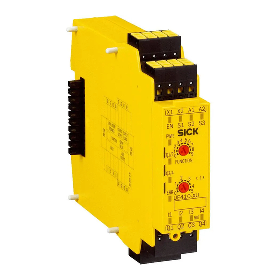
SICK Flexi Classic Operating Instructions Manual (128 pages)
Safety controller
Brand:
SICK
| Category:
Controller
| Size: 3 MB
Table of Contents
Table of Contents
3
About this Document
7
Purpose of this Document
7
Scope
7
Target Groups of These Operating Instructions
7
Symbols and Document Conventions
7
Safety Information
11
General Safety Notes
11
Intended Use
11
Requirements for the Qualification of Personnel
12
Product Description
13
Specific Features
13
Design
14
Main Module UE410-MU
14
Main Module UE410-GU
14
Input Expansion Module UE410-8DI
15
Input/Output Extension Module UE410-XU
15
UE410-2RO/UE410-4RO Output Modules
16
Gateways
16
Module Overview, Adjustments and Facilities for Connecting Sensors
16
Main Module UE410-MU
18
Operating Elements and Status Indicators
21
Terminal Assignment
22
Outputs
22
Main Module UE410-GU
23
Operating Elements and Status Indicators
24
Terminal Assignment
25
Global Emergency Stop with the UE410-GU
25
Local Emergency Stop on the UE410-GU
27
Inputs
28
Outputs
28
Connection of One UE410-8DI Switch
29
Power-Up Delay and Response Time of the UE410-GU
29
Diagnostics and Troubleshooting for the UE410-GU
30
UE410-SD Main Module
31
Status Indicators
31
Terminal Assignment
33
Wiring the Inputs
34
Wiring the Outputs
35
UE410-XU Module
35
Operating Elements and Status Indicators
35
UE410-MU/UE410-XU Programs
36
Program 1
36
Program 2
38
Programs 3.1 and 3.2
39
Program 4
40
Programs 5.1 and 5.2............................................................. 3.7.6 Program 6
41
Program 7
43
Program 8
44
Program 9
45
Connection of Sensors to the UE410-MU/UE410-XU
46
UE410-GU Programs
47
UE410-8DI Input Exptension Module
50
AND Link
50
OR Link
51
Bypass
52
Reciprocal Assignment - Mirror Mode
52
Connection of Sensors to the UE410-8DI
53
Operating Elements and Status Indicators
54
Inputs and Outputs
55
UE410-2RO/UE410-4RO Output Modules
55
Output Module UE410-2RO
56
Output Module UE410-4RO
56
Operating Elements and Status Indicators
57
UE410-2RO Inputs and Outputs
57
UE410-4RO Inputs and Outputs
58
Special Applications and Functions
59
RE300 Magnetic Safety Switch
59
IN4000 Inductive Safety Switch
60
Testable Single-Beam Photoelectric Safety Switches
61
Two-Hand Operation/Inching Mode
64
OR Function
65
Muting Function
66
Muting with Two Sensors
67
Muting Cycle
67
Muting Sensors
67
Placement of Muting Sensors
68
Muting with Two Sensors (a Sensor Pair), Crossed Placement
69
4-Sensor Muting, Sequential Layout
70
Muting with UE410-MU/UE410-XU
70
SICK Muting Sensors
71
Bypass
71
Wiring
72
Operation with Restart Interlock
72
Operation Without Restart Interlock
72
Operation with External Device Monitoring (EDM)
72
Retriggering of the Delayed Ossds
73
Grouping of Subsystems
75
ENABLE Input
76
Mounting
77
Mounting the Modules
77
Removing the Modules
78
Removing the Anti-Manipulation Cover
79
Electrical Installation
80
Application and Connection Diagrams
82
L21 on the UE410-MU/XU
82
Emergency Stop on the UE410-MU/XU
82
RE300 on the UE410-MU/XU
83
Two-Hand IIIC on the UE410-MU/XU
83
C2000 and Emergency Stop on the UE410-MU/XU, Two Hazardous
84
Areas
84
I11 on the UE410-MU/XU, Two Independent Hazardous Areas
84
IN4000 on the UE410-MU/XU
85
C4000 on the UE410-MU/XU, 2-Sensor Muting
85
Global Emergency Stop with Two UE410-GU
86
Configuration
87
Accepting the System Configuration
87
Commissioning
89
Changing the Telnet Password
89
Final Acceptance of the Application
89
Checks before Initial Commissioning
89
Regular Thorough Check of the Protective Device by Qualified Safety Personnel
90
Troubleshooting
91
Response to Faults
91
Replacement of a Module
91
Fault Indicators
92
Anti-Manipulation Measures
93
Decommissioning
94
Disposal
94
Technical Data
95
Regular Testing
95
Data Sheet
95
UE410-MU/UE410-XU Modules
95
UE410-GU Module
99
Data Sheet UE410-SD
102
Load Chart Q1, Q2, Q3 and U
103
OUT of UE410-SD
103
Input Extension Module UE410-8DI
104
UE410-2RO/UE410-4RO Output Modules
107
Electrical Endurance of Relay Modules UE4102RO/UE410-4RO
107
Dimensional Drawings
110
Dimensional Drawing UE410-SD400
111
Dimensional Drawing UE410-SD300
112
PRO, UE410-DEV, UE410-CAN (MM)
112
Ordering Information
113
Ordering Information for Modules
113
Accessories/Spare Parts
115
Single-Beam Photoelectric Safety Switches
115
Non-Contact Safety Switches
116
Safety Light Curtains and Multiple Light Beam Safety Devices
116
Safety Laser Scanners and Safety Camera System
116
Muting Lamp and Cable
117
Anti-Manipulation Cover
117
Glossary
118
Annex
121
Conformities and Certificates
121
EU Declaration of Conformity
121
UK Declaration of Conformity
121
Checklist for Initial Commissioning and Commissioning
121
List of Figures
123
List of Tables
125
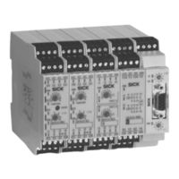
SICK Flexi Classic Operating Instructions Manual (124 pages)
Modular Safety Controller
Brand:
SICK
| Category:
Controller
| Size: 4 MB
Table of Contents
Table of Contents
3
1 About this Document
6
Function of this Document
6
Target Group
6
Information Depth
6
Scope
7
Abbreviations
7
Symbols Used
7
2 On Safety
11
Qualified Safety Personnel
11
Applications of the Device
11
Correct Use
12
General Safety Notes and Protective Measures
12
Environmental Protection
14
Disposal
14
Separation of Materials
14
3 Product Description
15
Special Features
15
Structure
16
UE410-MU Main Module
16
UE410-GU Main Module
17
UE410-8DI Input Extension Module
18
UE410-XU Input/Output Extension
18
UE410-2RO/UE410-4RO Output Modules
18
Gateways
18
Module Overview, Adjustments and Facilities for Connecting Sensors
19
UE410-MU Main Module
22
Controls and Status Indicators
24
Terminal Assignment
25
Outputs
26
UE410-GU Main Module
27
Controls and Status Indicators
28
Terminal Assignment
29
Global Emergency Stop with the UE410-GU
29
Local Emergency Stop on the UE410-GU
31
Inputs
32
Outputs
32
Connection of a UE410-8DI
33
Power-Up Delay and Response Time of the UE410-GU
33
Diagnostics and Troubleshooting for the UE410-GU
33
UE410-XU Module
35
Controls and Status Indicators
35
UE410-MU/UE410-XU Programs
36
Program 1
37
Program 2
38
Programs 3.1 and 3.2
39
Program 4
40
Programs 5.1 and 5.2
41
Program 6
42
Program 7
43
Program 8
44
Program 9
45
Connection of Sensors to the UE410-MU/UE410-XU
46
UE410-GU Programs
49
UE410-8DI Input Extension Module
51
AND Link
52
OR Link
53
Bypass
53
Reciprocal Assignment - Mirror Mode
54
Connection of Sensors to the UE410-8DI
54
Controls and Status Indicators
56
Inputs and Outputs
57
UE410-2RO/UE410-4RO Output Modules
57
Output Module UE410-2RO
57
Output Module UE410-4RO
58
Controls and Status Indicators
59
UE410-2RO Inputs and Outputs
59
UE410-4RO Inputs and Outputs
59
4 Special Applications and Functions
60
RE300 Magnetic Safety Switch
61
IN4000 Inductive Safety Switch
62
Testable Single-Beam Photoelectric Safety Switches
63
Two-Hand Operation/Jog Mode
66
OR Function
67
Muting Function
68
Muting with Two Sensors
69
Muting Cycle
69
Muting Sensors
69
Placement of Muting Sensors
70
Muting with Two Sensors (a Sensor Pair), Crossed Placement
71
4-Sensor Muting, Sequential Layout
72
Muting with UE410-MU/UE410-XU
72
SICK Muting Sensors
73
Bypass
74
Connecting S1, S2, S3
75
Operation with Restart Interlock
75
Operation Without Restart Interlock
75
Operation with External Device Monitoring (EDM)
75
Retriggering of the Delayed Ossds
76
Grouping of Subsystems
78
ENABLE Input
79
5 Mounting/Dismantling
80
Steps for Mounting the Modules
80
Steps for Dismantling the Modules
81
Removing the Anti-Manipulation Cover
82
6 Electrical Installation
83
7 Application Examples and Connection Diagrams
85
L21 on the UE410-MU/XU
85
Emergency Stop on the UE410-MU/XU
85
RE300 on the UE410-MU/XU
86
Two-Hand IIIC on the UE410-MU/XU
86
C2000 and Emergency Stop on the UE410-MU/XU, Two Hazardous Areas
87
I11 on the UE410-MU/XU, Two Independent Hazardous Areas
87
IN4000 on the UE410-MU/XU
88
C4000 on the UE410-MU/XU, 2-Sensor Muting
88
Global Emergency Stop with Two UE410-GU
89
8 Commissioning
90
Validation of the Application
90
Test Notes
91
Tests before the First Commissioning
91
Regular Testing
91
Regular Inspection of the Protective Device by Qualified Safety Personnel
91
9 Configuration
92
Accepting the System Configuration
92
10 Diagnostics
93
In the Event of Faults or Errors
93
Replacement of a Module
93
SICK Support
94
Error Indications of the ERR Error LED
94
Anti-Manipulation Measures
95
11 Technical Specifications
96
Data Sheet
96
UE410-MU/UE410-XU Modules
96
UE410-GU Module
101
UE410-8DI Input Extension Module
105
UE410-2RO/UE410-4RO Output Modules
107
Dimensional Drawings
111
UE410-MU and UE410-GU Main Modules
111
UE410-XU, UE410-8DI, UE410-2RO, UE410-4RO, UE410- PRO, UE410-DEV, UE410-CAN Modules
111
12 Ordering Information
112
Available Modules
112
Accessories/Spare Parts
115
Single-Beam Photoelectric Safety Switches
115
Non-Contact Safety Switches
116
Safety Light Curtains and Multiple Light Beam Safety Devices
117
Safety Laser Scanners and Safety Camera System
117
Muting Lamps and Cables
117
Anti-Manipulation Cover
117
13 Annex
118
Compliance with EU Directives
118
Manufacturer's Checklist
118
List of Tables
119
List of Illustrations
120
Advertisement
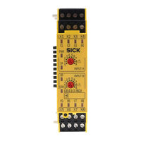
SICK Flexi Classic Operating Instructions Manual (48 pages)
Modular safety controller
Brand:
SICK
| Category:
Controller
| Size: 4 MB
Table of Contents
Table of Contents
3
1 Ordering Information
5
Available Modules
5
Anti-Manipulation Cover
5
2 About this Document
6
Purpose of this Document
6
Target Group
6
Information Depth
6
Scope
6
Abbreviations Used
7
Symbols Used
7
3 Safety
10
Qualified Safety Personnel
10
Applications of the Device
10
Intended Use
11
General Safety Notes and Protective Measures
11
Protecting the Environment
12
Disposal
12
Material Separation
12
4 Product Description
13
Specific Features
13
Design
13
Main Module UE410-MU
13
Module Overview, Adjustments and Facilities for Connecting Sensors
14
Main Module UE410-MU
15
Operating and Status Indicators
17
Terminal Assignment
18
Outputs
18
UE410-MU Programs
19
Program 1
20
Program 2
21
Programs 3.1 and 3.2
22
Program 4
23
Programs 5.1 and 5.2
24
Program 6
25
Program 7
26
Program 8
27
Program 9
28
Connection of Sensors to the UE410-MU/UE410-XU
29
5 Mounting/Dismantling
31
Steps for Mounting the Modules
31
Steps for Dismantling the Modules
32
Removing the Anti-Manipulation Cover
32
6 Electrical Installation
34
7 Commissioning
35
Validation of the Application
35
Inspection Instructions
35
Checks before Initial Commissioning
35
Regular Testing
36
Regular Thorough Check of the Protective Device by Qualified Safety Personnel
36
8 Configuration
37
Accepting the System Configuration
37
9 Diagnostics
38
Response to Faults
38
Replacement of a Module
38
SICK Support
38
Error Indications of the ERR Error LED
38
Anti-Manipulation Measures
39
10 Technical Data
41
Data Sheet
41
UE410-MU Modules
41
Dimensional Drawings
45
UE410-MU Main Module
45
11 Annex
46
Compliance with EU Directives
46
Manufacturer's Checklist
46
List of Tables
46
List of Figures
47
Advertisement
Related Products
SICK Flexi Soft
SICK Flexi Classic series
SICK Flexi Compact
SICK FlexChain
SICK Flexi Loop
SICK flexLock
SICK FLOWSIC600-XT
SICK FLOWSIC30
SICK FLPS Series
SICK FLOWSIC100-XT-M
SICK Categories
Accessories
Security Sensors
Measuring Instruments
Scanner
Barcode Reader
More SICK Manuals
Login
Sign In
OR
Sign in with Facebook
Sign in with Google
Upload manual
Upload from disk
Upload from URL