Sign In
Upload
Manuals
Brands
Servomex Manuals
Industrial Equipment
SERVOTOUGH Laser SP 2930
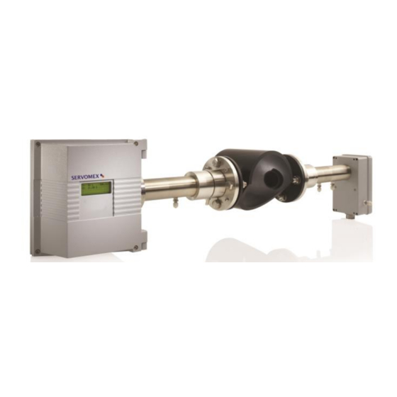
Servomex SERVOTOUGH Laser SP 2930 Manuals
Manuals and User Guides for Servomex SERVOTOUGH Laser SP 2930. We have
1
Servomex SERVOTOUGH Laser SP 2930 manual available for free PDF download: Operator's Manual
Servomex SERVOTOUGH Laser SP 2930 Operator's Manual (97 pages)
Brand:
Servomex
| Category:
Industrial Equipment
| Size: 1 MB
Table of Contents
Table of Contents
3
1 Introduction
6
Safety Information
6
General
6
Servotough Laser Monitor
6
Measuring Principle
8
Figure 1-1: Measuringp
8
Instrument Description
9
Figure 1-2: General View of
9
Figure 1-3: Block Diagram of Instrument Electronics
10
Software
11
Laser Classification
11
Product Data
12
2 Preparations
13
Tools and Other Equipment
13
Flow Conditions at Measuring Point
13
Monitor Placement
13
Figure 2-1: Transmitter and Receiver Installation Tolerances
13
Flanges and Stack Hole Requirements
14
Figure 2-2: Flanges with and Without Valve
14
Figure 2-3: Flange Angle Alignment Tolerances
14
Figure 2-4: Flange Line
15
Cables and Electrical Connections
16
3 Installation
17
Installation and Adjustments
21
Figure 3-1: Servotough L
21
SERVOTOUGH Laser Installation
22
Purging of Flanges
26
Purging of Transmitter and Receiver for Measurement Purpose
26
Start-Up
27
Start-Up of Electronics
27
Figure 3-2: Purging of the Transmitter and Receiver Units
27
Alignment of Transmitter/Receiver Using IR Card
28
Alignment of Transmitter Unit
28
Figure 3-3: Alignment Mechanism Details
29
Figure 3-4: Ir
29
Alignment of Receiver Unit
30
Alignment of Transmitter/Receiver Using Red Laser Alignment Jig
31
Alignment of Transmitter Unit
31
Figure 3-5: Red Laser Alignment Jig
31
Alignment of Receiver Unit
33
Tuning for Maximum Signal
34
Connecting Apc
35
Connecting a Modem
35
4 The Service Program
36
Software Start-Up
37
The Measurement Menu
38
The Program Menus
41
Plot Readings
41
Second Harmonic Signal
41
Log Readings
42
View Error Log
43
Measurement Configuration
44
Figure 4-1: Optical Lengths Needed for Setting Initial Parameters
47
Gas Specific Parameters
49
Calibrate Instrument
52
TCP/IP and Modem Configuration
54
File Download/Upload
55
Manual Instrument Control
56
5 Operation, Maintenance and Calibration
57
Operating Modes
57
Maintenance
59
Routine Maintenance
59
Cleaning of Optical Windows
60
Alignment of the Instrument
60
Optimising the Flange Purge Flow
60
Calibration of the Instrument
61
Table 5-1: Recommended Gas Concentrations for Calibration
62
Figure 5-1: Calibration Cell with Monitor Connected
63
PROPORTIONAL Versus GLOBAL Calibration
64
Troubleshooting the Instrument
65
Table 5-2: Instrument Lcd
68
Error Messages
68
6 Electrical Connections
69
Transmitter Unit Interface
69
Figure 6-1:Transmitter Unit Electronic Interface
70
Figure 6-2: Internal Input and Output Connectors
71
Electrical Safety
72
Power Cable Connections
73
Mains Power Connection
73
Figure 6-3: Protective Earth Connection
74
Figure 6-4: Mains Power Connections
74
DC Power Connection
75
Functional Earth (Ground) Connection
75
Figure 6-5: DC
75
Receiver Cable Connections
76
Table 6-1: Transmitter Unit
76
Table 6-2: Receiver Unit
77
Current Loop (4-20 Ma) Input Connections (PLC)
78
Current Loop (4-20 M A)
78
Table 6-3: Transmitter Unit
78
Figure 6-6: Current Loop Input
79
Figure 6-7: Current Loop Input
79
Auxiliary Board Connections
80
Table 6-4: Transmitter Unit
80
Selection of Zero, Span and Maintenance Mode
81
Table 6-5: Selection of Zero
81
Rs-232 and Ethernet Connections
82
Connection
82
Table 6-6: Transmitter Unit
82
Table 6-7: Transmitter Unit
82
Figure 6-8: Power Electronics Card Fuses and
83
Transmitter Board - Fuses and Led's
83
Relay Indications
84
Table 6-8: Relay Indications and Outputs
84
Configuring Relay 3 Output
85
Normal Configuration of Relay-3, "Gas Alarm
85
Inverted Configuration of Relay-3, "Gas Alarm
86
Maintenance Configuration of Relay-3
86
Inverting Relay-3 Output by Hardware Switch
86
7 Span and Zero Check Options
87
Span Check with Flow through Cell
87
Span and Zero Check with Internal Sealed Cell
88
Appendix 1 Compliance and Standards Information
89
Appendix 2 Disposal in Accordance with the Waste Electrical and Electronic Equipment (Weee) Directive
90
Appendix 3 Atex Directive and Other Non-European Hazardous Area Approvals
91
Appendix 4 - Equipment Protection Levels - Atex/Iecex
93
Appendix 5 - Process Considerations - Atex/Iecex Only
94
Appendix 6 - Explanation of Coding - Atex/Iecex
96
Appendix 7 - Explanation of Coding - Csa
97
Advertisement
Advertisement
Related Products
Servomex SERVOFLEX MiniFood Pack
Servomex SERVOPRO Plasma
Servomex SERVOPRO FID
Servomex SERVOPRO MultiExact
Servomex SERVOFLEX MiniMP
Servomex SERVOPRO Chroma
Servomex SERVOTOUGH Oxy
Servomex SERVOTOUGH LaserSPII mini
Servomex SERVOTOUGH SpectraExact 2500 Series
Servomex SERVOTOUGH Laser 3 Plus
Servomex Categories
Measuring Instruments
Analytical Instruments
Transmitter
Industrial Equipment
More Servomex Manuals
Login
Sign In
OR
Sign in with Facebook
Sign in with Google
Upload manual
Upload from disk
Upload from URL