
Subscribe to Our Youtube Channel
Summary of Contents for Servomex SERVOTOUGH Laser SP 2930
- Page 1 SERVOTOUGH Laser SP (Model 2930) Operator Manual (For Windows Software v. 6.1) Part Number: 02930001A Revision: Language: UK English...
- Page 2 This page is intentionally left blank.
-
Page 3: Table Of Contents
SERVOTOUGH Laser SP Monitor, Operator Manual 02930001A_7 TABLE OF CONTENTS INTRODUCTION ........................4 .......................4 AFETY NFORMATION ..........................4 ENERAL ......................6 EASURING PRINCIPLE ......................7 NSTRUMENT DESCRIPTION ..........................9 OFTWARE ......................9 ASER CLASSIFICATION ........................10 RODUCT DATA PREPARATIONS ........................11 ....................11 OOLS AND OTHER EQUIPMENT ................ - Page 4 SERVOTOUGH Laser SP Monitor, Operator Manual 02930001A_7 ..................59 ALIBRATION OF THE INSTRUMENT 5.4.1 PROPORTIONAL versus GLOBAL calibration..............62 ..................63 ROUBLESHOOTING THE INSTRUMENT ELECTRICAL CONNECTIONS ....................67 ....................67 RANSMITTER UNIT INTERFACE ......................70 LECTRICAL AFETY ....................71 OWER CABLE CONNECTIONS 6.3.1 Mains Power Connection ....................
- Page 5 SERVOTOUGH Laser SP Monitor, Operator Manual 02930001A_7 FIGURES 1-1: M SERVOTOUGH L ............6 IGURE EASURING RINCIPLE ASER ONITOR 1-2: G SERVOTOUGH L ..............7 IGURE ENERAL VIEW OF ASER ONITOR 1-3: B ................8 IGURE LOCK DIAGRAM OF INSTRUMENT ELECTRONICS 2-1: T ............
-
Page 6: Introduction
SERVOTOUGH Laser SP Monitor, Operator Manual 02930001A_7 INTRODUCTION Safety Information Read this manual and ensure that you fully understand its content before you attempt to install, use or maintain the Laser monitor. Important safety information is highlighted in this manual as WARNINGs and CAUTIONs, which are used as follows: WARNING Warnings highlight specific hazards which, if not taken into account, may... - Page 7 SERVOTOUGH Laser SP Monitor, Operator Manual 02930001A_7 Please read entire manual carefully before using the SERVOTOUGH Laser Monitor. It is a sophisticated instrument utilising state-of-the-art electronic and laser technology. Installation and maintenance of the instrument require care and preparation and should only be attempted by competent personnel. Failure to do so may damage the instrument and void the warranty.
-
Page 8: Measuring Principle
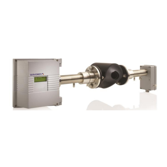
SERVOTOUGH Laser SP Monitor, Operator Manual 02930001A_7 Measuring principle The SERVOTOUGH Laser Monitor is an optical instrument designed for continuous in-situ gas monitoring in stack, pipes, process chambers and similar applications and is based on tunable diode laser absorption spectroscopy (TDLAS). The SERVOTOUGH Laser Monitor utilises a transmitter/receiver configuration (mounted diametrically opposite each other) to measure the average gas concentration along the line-of-sight path. -
Page 9: Instrument Description
SERVOTOUGH Laser SP Monitor, Operator Manual 02930001A_7 NOTE: The SERVOTOUGH Laser Monitor measures the concentration of only the FREE molecules of the specific gas, thus not being sensitive to the molecules bound with some other molecules into complexes and to the molecules attached to or dissolved in particles and droplets. -
Page 10: Figure 1-3: Block Diagram Of Instrument Electronics
SERVOTOUGH Laser SP Monitor, Operator Manual 02930001A_7 The receiver electronics are connected with the transmitter electronics with a multi- core cable. The detected absorption signal from the photo-detector is amplified and transferred to the transmitter unit through this cable. The same cable transfers the required power from the transmitter unit to the receiver unit. -
Page 11: Software
SERVOTOUGH Laser SP Monitor, Operator Manual 02930001A_7 Software Software for the SERVOTOUGH Laser Monitor consists of 2 programs: A program hidden to the user and integrated in the CPU electronics, running the micro controller on the CPU card. The program performs all necessary calculations and self-monitoring tasks. -
Page 12: Product Data
Environmental conditions: Operating temperature C to +55 C (-4⁰F to +131⁰F) Note: +65⁰C operation possible for selected applications. (Contact Servomex for availability) Storage temperature C to +55 C (-4⁰F to +131⁰F) Apparatus is suitable for outdoor use Operating ambient pressure range: 101.3 kPa, -20%, +10% (1.013 bar -20%, +10%) -
Page 13: Preparations
SERVOTOUGH Laser SP Monitor, Operator Manual 02930001A_7 PREPARATIONS Tools and other equipment The following equipment is necessary to install and calibrate the equipment: • 2 pcs open-end spanners for M16 bolts • 1 pcs Allen key 5 mm for the locking screws on flanges and Tx lid screws •... -
Page 14: Flanges And Stack Hole Requirements
SERVOTOUGH Laser SP Monitor, Operator Manual 02930001A_7 Flanges and stack hole requirements The monitor requires two holes diametrically opposite to each other, at least 50 mm in diameter. Standard flanges used for connection are DN50/PN10 with an inner diameter of 50 mm and an outer diameter of 165 mm. The flanges can either be welded directly to the process, or optionally be part of a valve connected to the process for safety purposes. -
Page 15: Figure 2-4: Flange Line
SERVOTOUGH Laser SP Monitor, Operator Manual 02930001A_7 The flange line-up should initially be better than 1.5 as specified in Figure 2-3. The distance between the imaginary parallel lines AB and CD (Figure 2-4) should fulfil the specifications in the table to ensure that the tubes do not shield the laser beam. -
Page 16: Cables And Electrical Connections
The transmitter and receiver units are connected with a cable (receiver cable). This cable should not be exchanged without SERVOMEX’s permission nor should the cable length be modified by more than 20 m as this may influence calibration or the instrument’s accuracy. -
Page 17: Installation
Laser monitor may be damaged. WARNING The Laser monitors are not suitable for use in hazardous areas unless the correct certification labels have been affixed by Servomex and a suitable purge control system is installed (EX1 versions). Instructions Specific to Hazardous Area Installations... - Page 18 SERVOTOUGH Laser SP Monitor, Operator Manual 02930001A_7 European and International Approvals (EX1 and EX2) The following instructions apply to equipment covered by certificate numbers: Baseefa 10ATEX0100X The following instructions also apply to equipment covered by certificate number IECEx BAS 10.0038X Mains Power details: Process Dust Surface...
- Page 19 SERVOTOUGH Laser SP Monitor, Operator Manual 02930001A_7 Note: For an explanation of the coding refer to Appendix 6 • The equipment may be located where flammable gases and vapours of groups llA, llB or llC or combustible dusts of groups IIIA or IIIB may be present. The equipment is only certified for use in ambient temperatures in the range - 20°C to +65°C.
- Page 20 SERVOTOUGH Laser SP Monitor, Operator Manual 02930001A_7 North American Approvals – CS2 The following instructions apply to equipment covered by certificate numbers: CSA 11.2393527X Mains Power details: Process Flange Dust Surface Ambient Temperature T Class Temperature Temperature Range ≤65°C T75°C ≤100°C T100°C -20°C≤Ta≤+60°C...
-
Page 21: Installation And Adjustments
SERVOTOUGH Laser SP Monitor, Operator Manual 02930001A_7 Installation and adjustments The installation procedure described in this section refers to Figure 3-1. CAUTION Please note only trained persons should install SERVOTOUGH LaserSP monitors. Training must include practical actions of aligning receiver and transmitter units on mounting flanges using an alignment tool. -
Page 22: Servotough Laser Installation
SERVOTOUGH Laser SP Monitor, Operator Manual 02930001A_7 3.1.1 SERVOTOUGH Laser installation WARNING You must not modify the Laser Monitor in any way (either mechanically or electrically). If you do, the certification of the monitor will be invalidated, and it may not operate safely. WARNING The Laser Monitor must be installed by a suitably skilled and competent technician or engineer in accordance with this manual... - Page 23 SERVOTOUGH Laser SP Monitor, Operator Manual 02930001A_7 WARNING If using toxic, asphyxiant or flammable sample or calibration gases, always purge the enclosures with non-hazardous gas during operation to reduce the risk of hazardous concentrations accumulating within the monitor. Purge the enclosures for a suitable time before opening to ensure any concentrations are reduced to safe levels.
- Page 24 SERVOTOUGH Laser SP Monitor, Operator Manual 02930001A_7 WARNING EX1 where appropriate, the user must refer to the detailed instructions provided in the manual supplied with the purge control unit. WARNING The installation of the Laser Monitor in a hazardous area must comply with any ‘Special Conditions for Safe Use’...
- Page 25 SERVOTOUGH Laser SP Monitor, Operator Manual 02930001A_7 Both receiver and transmitter units have optical windows installed by the factory. They should not be taken off and their angular positions should not be changed. This is important for successful alignment. Please note that there is no separate mains switch on instrument.
-
Page 26: Purging Of Flanges
SERVOTOUGH Laser SP Monitor, Operator Manual 02930001A_7 Connect optional output signals (4-20mA, warning relays, etc.) to the “Auxiliary” terminals in the transmitter unit (use an auxiliary cable entry, Figure 6-1). Refer to Section 6.7. Input signals such as external temperature and pressure probes are connected to the assigned terminals in the transmitter unit. -
Page 27: Start-Up
SERVOTOUGH Laser SP Monitor, Operator Manual 02930001A_7 Transmitter Receiver Flow Flow Input Flow Output Figure 3-2: Purging of the transmitter and receiver units. Please note this is application dependant. For long distances between the TU and RU, it may be more convenient to have two separate lines for cooling/purging the RU and TU. -
Page 28: Alignment Of Transmitter/Receiver Using Ir Card
SERVOTOUGH Laser SP Monitor, Operator Manual 02930001A_7 and transmitter units, i.e. the laser beam does not hit the detector inside the receiver unit. If you use an IR card for alignment of the transmitter/receiver refer to Section 3.3. If you use a red laser alignment jig for alignment of the transmitter/receiver refer to Section 3.4. -
Page 29: Figure 3-3: Alignment Mechanism Details
SERVOTOUGH Laser SP Monitor, Operator Manual 02930001A_7 Cross-sectional view DN50 flange Front view Locking STACK screws WALL Adjustment screws (M16) RIGHT LEFT 3 – 6mm DOWN Figure 3-3: Alignment mechanism details Having found the laser beam, adjust the beam to the centre of the hole by carefully adjusting the adjustment screws on the transmitter side. -
Page 30: Alignment Of Receiver Unit
SERVOTOUGH Laser SP Monitor, Operator Manual 02930001A_7 3.3.2 Alignment of receiver unit Mount the receiver unit to the alignment unit on the receiver side. Check the transmission reading on the transmitter unit LCD. It is recommended that two people with a radio link perform this operation with one working on the RU and the other on the TU. -
Page 31: Alignment Of Transmitter/Receiver Using Red Laser Alignment Jig
SERVOTOUGH Laser SP Monitor, Operator Manual 02930001A_7 Alignment of transmitter/receiver using red laser alignment jig WARNING LASER ALIGNMENT JIG – CLASS 3R LASER PRODUCT LASER RADIATION – AVOID DIRECT EYE CONTACT Note that the red laser alignment jig (including laser pen) is not Ex certified. This alignment jig cannot be use where there is a flammable atmosphere present in the ‘Outside atmosphere’... - Page 32 SERVOTOUGH Laser SP Monitor, Operator Manual 02930001A_7 Switch off the unit, and disconnect both the transmitter and receiver units from their alignment flanges by loosening the corresponding mounting nuts. Remove the adapter ring (no.4 in Figure 3-1) from both the transmitter and receiver alignment unit.
-
Page 33: Alignment Of Receiver Unit
SERVOTOUGH Laser SP Monitor, Operator Manual 02930001A_7 3.4.2 Alignment of receiver unit Disconnect the red laser alignment jig from the transmitter alignment unit and remove the target window from the receiver alignment unit. Remount the target window on the transmitter alignment unit and connect the red laser alignment jig onto the receiver alignment unit. -
Page 34: Tuning For Maximum Signal
SERVOTOUGH Laser SP Monitor, Operator Manual 02930001A_7 Tuning for maximum signal The alignment voltage varies from 0V at 0% transmission to –3V (typically, for some applications with large distance between the RU and TU >4 m, the voltage can be - 1.0V and -1.5 V) at 100% transmission. -
Page 35: Connecting Apc
SERVOTOUGH Laser SP Monitor, Operator Manual 02930001A_7 Connecting a PC Please note that the PC should be placed in a non-hazardous (safe) area. For long distance communication we recommend use of the optional Ethernet connection. The software for service communication with the SERVOTOUGH Laser Monitor is supplied with the instrument and will run under Windows98/2000/XP/VISTA and Windows 7. -
Page 36: The Service Program
SERVOTOUGH Laser SP Monitor, Operator Manual 02930001A_7 THE SERVICE PROGRAM The instrument calculates the gas concentration from the measured signal, which depends on several process parameters. The instrument must therefore be configured for the specific installation. With the service program the user communicates with the instrument and changes installation or process relevant settings. -
Page 37: Software Start-Up
SERVOTOUGH Laser SP Monitor, Operator Manual 02930001A_7 Software start-up After starting the program a welcome screen will display a selection of instrument to PC connections: SERVOTOUGH Laser Gas Monitor The version of the service program is printed in the right bottom corner (in the example above V1.2.1.3). -
Page 38: The Measurement Menu
Advanced mode that enables full access to all the instrument setting parameters. This program mode should be used during service adjustment of the instrument. Your local distributor or SERVOMEX can provide the password on request. Note that if the connection is moved to another instrument the program must be shut down and run again. - Page 39 SERVOTOUGH Laser SP Monitor, Operator Manual 02930001A_7 harmonic signal). By pressing <Exit menu> one can always go back to the previous menu. The description of each menu will follow. The rest of the screen is used to display different readings/parameters. By default only the main readings/parameters are displayed.
- Page 40 SERVOTOUGH Laser SP Monitor, Operator Manual 02930001A_7 Line amplitude: Relative measure of the peak of the absorption line of the second harmonic signal. If this value approaches 0.5-1.0 the absorption is strong and saturation of the AD converter may be very close (actual saturation initiates the ERROR).
-
Page 41: The Program Menus
SERVOTOUGH Laser SP Monitor, Operator Manual 02930001A_7 Laser temp. error: The amplified difference in Volts between the measured Laser temp and the reference value. Should be around 0.000. It indicates the quality of the laser temperature regulation and thus the quality of the wavelength stabilization. Peltier pump (A): The current drawn by the Peltier element. -
Page 42: Log Readings
SERVOTOUGH Laser SP Monitor, Operator Manual 02930001A_7 readings> in the File download/upload menu (Section 4.3.9). The scale of each axis is modified by clicking on the axis label. It is possible to open a previously saved signal and scale it to compare with existing signal. -
Page 43: View Error Log
<Rewind system log 100 lines> and subsequently <Save system log>. In case of instrument failure it is always useful to download the error log and the system log and send both files to SERVOMEX for diagnostics. SERVICE PROGRAM... -
Page 44: Measurement Configuration
SERVOTOUGH Laser SP Monitor, Operator Manual 02930001A_7 4.3.5 Measurement configuration In this menu the most important parameters can be set: Gas pressure (page 1) Gas temperature (page 1) Pressure / temperature input method (page 1) Pressure / temperature PLC input range (page 1) Concentration averaging (page 2) - Page 45 This method is only applicable for instruments measuring gas temperature like the O + Temperature monitor. Method “Serial”: Pressure and temperature input through RS-232 or Ethernet connector (requires special data packet, contact SERVOMEX for details). SERVICE PROGRAM...
- Page 46 SERVOTOUGH Laser SP Monitor, Operator Manual 02930001A_7 Optical path through gas (m) The length (in meters) of the optical path through the gas to be measured (Lg in Figure 4-1). It is normally equal to the stack diameter or the free space between insertion tubes.
-
Page 47: Figure 4-1: Optical Lengths Needed For Setting Initial Parameters
SERVOTOUGH Laser SP Monitor, Operator Manual 02930001A_7 Transmitter Receiver Unit Unit Figure 4-1: Optical lengths needed for setting initial parameters. Gas temperature in flanges (C) The average temperature of the gas in the flanges in degrees Celsius. If the measured gas is not present in the flanges, the flange temperature is irrelevant. Note: Proper setting of the optical path parameters is important for correct measurements. - Page 48 SERVOTOUGH Laser SP Monitor, Operator Manual 02930001A_7 Specifies the number of values used for spectral temperature averaging. Instrument time The instrument has a built-in clock, which also runs when power is off. Using this menu the instrument time should be set equal to the local time. The current instrument time is only downloaded from the instrument after an update of parameters or explicitly after pressing <Reload readings (P, T, date)>.
-
Page 49: Gas Specific Parameters
SERVOTOUGH Laser SP Monitor, Operator Manual 02930001A_7 where N is the originally measured gas concentration on wet basis and H O(%) is the input H O concentration in % vol. The factor that multiplies N is Dry conversion factor which can be monitored in the Measurements menu. H2O input method The following input methods for the H O concentration can be selected: Fixed,... - Page 50 SERVOTOUGH Laser SP Monitor, Operator Manual 02930001A_7 The relative units g/Nm , mg/Nm and µg/Nm are the values obtained from the µ ) to ‘normal’ pressure and conversion of the absolute units (g/m , mg/m temperature assuming the ideal gas low. According to the European standard which applies for the SERVOTOUGH Laser Monitor these values are P = 1.013 Bar and T = 273.1 K.
- Page 51 SERVOTOUGH Laser SP Monitor, Operator Manual 02930001A_7 gases, although the alarm relay is common. Thus, if the concentration of any of the measured gas is above its alarm level, the alarm relay is activated. To exclude one or several gases from activating the alarm the corresponding alarm levels are set to deliberately unreachable values.
-
Page 52: Calibrate Instrument
SERVOTOUGH Laser SP Monitor, Operator Manual 02930001A_7 4.3.7 Calibrate instrument Calibration of all gases and the spectral temperature (if applicable) is carried out in this menu. The example below is for an instrument measuring two gases. Smx-sjr There are two available calibration modes: "PROPORTIONAL" and "GLOBAL", which can be toggled. - Page 53 The new calibration will be stored permanently. The calibration time will be updated automatically. SERVOMEX calibrates all instruments under controlled conditions using certified gas. This calibration is then verified for the specified range of temperature and pressure. There is no need to calibrate the instrument upon reception. However, if...
-
Page 54: Tcp/Ip And Modem Configuration
SERVOTOUGH Laser SP Monitor, Operator Manual 02930001A_7 4.3.8 TCP/IP and modem configuration TCP/IP parameters of the embedded Ethernet board (optional) and the initialising string of a modem can be configured using this menu. Modem init string This string is used to initialise the modem connected to the transmitter unit via a null modem cable (see Section 3.7). -
Page 55: File Download/Upload
SERVOTOUGH Laser SP Monitor, Operator Manual 02930001A_7 4.3.9 File download/upload This menu allows the user to save/restore instrument data to/from file. Two different types of data can be downloaded from the instrument to a PC and saved into ASCII text files: the instrument readings and the instrument settings. The readings file contains the measured data shown in the Measurements menu. -
Page 56: Manual Instrument Control
SERVOTOUGH Laser SP Monitor, Operator Manual 02930001A_7 It is possible to upload instrument settings from a PC, thus updating the instrument with new settings or restoring a previously saved instrument configuration. It is important to ensure that the settings file is correct and actually belongs to this SERVOTOUGH Laser Monitor. -
Page 57: Operation, Maintenance And Calibration
SERVOTOUGH Laser SP Monitor, Operator Manual 02930001A_7 OPERATION, MAINTENANCE AND CALIBRATION Operating modes After having set all necessary instrument parameters as described in chapter 4, the instrument is ready for operation. During continuous operation, the SERVOTOUGH Laser Monitor may be in any of these three modes: 1. - Page 58 SERVOTOUGH Laser SP Monitor, Operator Manual 02930001A_7 The measuring mode is defined by input through two channels, either • through digital communication (e.g. with service program see Section 4.2). • or electrical signals through the AUX connector (see Section 6.7.1 and Table 6-5).
-
Page 59: Maintenance
5.2.1 Routine maintenance SERVOMEX gas monitors have no moving parts and require no consumables. For best performance, however, we recommend to routinely carry out the following steps: • Check optical transmission regularly (daily). This can be done automatically by use of instrument output (if ordered) or WARNING relay or similar. -
Page 60: Cleaning Of Optical Windows
SERVOTOUGH Laser SP Monitor, Operator Manual 02930001A_7 5.2.2 Cleaning of optical windows Dust or other contamination on the optical windows will reduce the signal level. The instrument is designed to allow a considerable reduction of the signal level (down to 10-30%) without influencing the quality of the measurements. -
Page 61: Calibration Of The Instrument
O SERVOTOUGH Laser Monitors are normally calibrated using calibration gas generators (e.g. type HovaCAL) to generate defined moisture concentrations. For alternative methods please contact SERVOMEX or your local distributor. Since the calibration of the instrument affects all subsequent measurements, the user should verify the need for a new calibration. -
Page 62: Table 5-1: Recommended Gas Concentrations For Calibration
1 m. To obtain the optimal signal-to-noise ratio when using our calibration cell (accessory available from SERVOMEX), the gas concentrations of Table 5-1 should be used for our standard monitors (contact your local distributor for non standard monitors). Note that the optical path-length for the standard SP monitor is 0.712 m when mounted onto... -
Page 63: Figure 5-1: Calibration Cell With Monitor Connected
SERVOTOUGH Laser SP Monitor, Operator Manual 02930001A_7 The instrument can now be mounted back in its measuring position. T - s e n s o r g a s o u t l e t g a s i n l e t R e c e i v e r T r a n s m i t t e r P - s e n s o r... -
Page 64: Proportional Versus Global Calibration
SERVOTOUGH Laser SP Monitor, Operator Manual 02930001A_7 Special care should be taken for reactive and “sticky” gases such as HF, NH HCl and H S. Because of the nature of these gases, it is difficult to obtain the required concentration in the calibration cell due to adsorption and de-sorption in the connection tubes and within the cell itself. -
Page 65: Troubleshooting The Instrument
SERVOTOUGH Laser SP Monitor, Operator Manual 02930001A_7 USE GLOBAL calibration: • If spectral properties of laser are believed to have drifted. This can be evaluated by qualified service personnel from dump-files recorded with the instrument when it is measuring on a calibration gas. •... - Page 66 SERVOTOUGH Laser SP Monitor, Operator Manual 02930001A_7 Fault message Explanations and actions WARNING « Low transmission » The optical transmission has dropped below the limit for reliable measurements. This might indicate misalignment of the optical units or contamination of the optical windows.
- Page 67 SERVOTOUGH Laser SP Monitor, Operator Manual 02930001A_7 Fault message Explanations and actions « Ex-read out of range » WARNING Input current from external gas sensor is either above 22 mA or below 3.2 mA. Check Extra (Flow) current input. The power supply voltage input to the instrument «...
-
Page 68: Table 5-2: Instrument Lcd
SERVOTOUGH Laser SP Monitor, Operator Manual 02930001A_7 Fault message Explanations and actions ERROR « Low line position » The instrument has detected a spectroscopic fault. This « High line position » can have several causes: « No absorption line » 1) Unknown interference gas in process. -
Page 69: Electrical Connections
SERVOTOUGH Laser SP Monitor, Operator Manual 02930001A_7 ELECTRICAL CONNECTIONS Note that in the table columns labelled “ DESCRIPTION”, the indicated polarities of the items are for naming only and do not necessarily reflect the polarity of real voltages. All potentials are floating and none of them should be grounded to box. This applies to all connection tables. -
Page 70: Figure 6-1:Transmitter Unit Electronic Interface
SERVOTOUGH Laser SP Monitor, Operator Manual 02930001A_7 PURGE INLET: • Compression Fitting for 1/4” OD Pipe or Blank RECEIVER CABLE ENTRY ½” NPT: (Signals & Power to/from Receiver) • +/-15V DC • Direct Signal • Harmonic Signal • RU Temperature •... -
Page 71: Figure 6-2: Internal Input And Output Connectors
SERVOTOUGH Laser SP Monitor, Operator Manual 02930001A_7 Figure 6-2: Internal input and output connectors ELECTRICAL CONNECTIONS... -
Page 72: Electrical Safety
SERVOTOUGH Laser SP Monitor, Operator Manual 02930001A_7 The receiver cable connects the transmitter and receiver unit. The power cable connects power to the transmitter unit. Custom auxiliary cables (e.g. 4–20 mA output) can be connected through the auxiliary cable entries. The receiver and main power cable entries are ½”... -
Page 73: Power Cable Connections
SERVOTOUGH Laser SP Monitor, Operator Manual 02930001A_7 Power cable connections 6.3.1 Mains Power Connection WARNING AC Power for EX1 versions may only be connected via a suitably certified Purge Control Unit. The power cable shall be a three core cable with Line/Live (L), Neutral (N), Earth/Ground (E) conductors. -
Page 74: Figure 6-3: Protective Earth Connection
SERVOTOUGH Laser SP Monitor, Operator Manual 02930001A_7 a) Protective earth terminal PROTECTIVE EARTH BOND TO POWER SUPPLY. SHAKEPROOF WASHER ( 2 ) WARNING! DO NOT REMOVE THIS CONNECTION USER FITTED PROTECTIVE EARTH BOND. b) Method of fixing protective earth connection Figure 6-3: Protective earth connection Figure 6-4: Mains power connections HAPTER... -
Page 75: Dc Power Connection
SERVOTOUGH Laser SP Monitor, Operator Manual 02930001A_7 6.3.2 DC Power Connection A direct connection can be made to a 24V DC connection (20-30V DC) available on site. CAUTION To comply with EMC requirements, you must use screened cables. It is recommended that the screens are terminated at the cable glands or local earth studs. -
Page 76: Receiver Cable Connections
CAUTION You must use the cable provided by Servomex to connect the receiver to the transmitter. Table 6-1 and Table 6-2 show wiring of the receiver cable on the transmitter side and the receiver side, respectively. -
Page 77: Table 6-2: Receiver Unit
SERVOTOUGH Laser SP Monitor, Operator Manual 02930001A_7 Direct – direct laser transmission signal from Receiver detector, signal may be used for alignment purposes (see Sections 3.3 – 3.5). 2. Harmonic – detected second harmonic signal from Receiver detector. Servo – control of servomotor moving sealed cell. Note that the voltage for alignment purposes (see Sections 3.3 –... -
Page 78: Current Loop (4-20 Ma) Input Connections (Plc)
Table 6-3 i.e. the probe outputs are connected to the screw terminals marked with Probe+ and Probe- (or +24V for passive probe). Probe is referred to either Temperature, Pressure or Extra (Flow). Note that conductors with area 0.14-0.5 (AWG 26-20) must be used (SERVOMEX recommends 0.25mm Junction list Terminal: Pair no:... -
Page 79: Figure 6-6: Current Loop Input
SERVOTOUGH Laser SP Monitor, Operator Manual 02930001A_7 External Instrument power +24V DC, 80mA Probes Main unit +24V (Transmitter) 4-20mA Signal in Probe+ probe 100 Probe- Signal return Probes AGND AGND Figure 6-6: Current loop input, active probe Instrument +24V DC, 80mA Probes Signal return Main unit... -
Page 80: Auxiliary Board Connections
Connect 4-20 mA outputs and relays contacts according to Table 6-4. Note that conductors with area 0.14-0.5 mm (AWG 26-20) must be used (SERVOMEX recommends 0.25 mm ). The cable outer diameter must be 7–12 mm. Junction list Terminal:... -
Page 81: Selection Of Zero, Span And Maintenance Mode
SERVOTOUGH Laser SP Monitor, Operator Manual 02930001A_7 PLC3 – not used. For dual gas instruments the outputs are configured as follows: PLC1 – output for gas-1 concentration, PLC2 – output for gas-2 concentration, PLC3 – optional output for transmission (4 mA=0%, 20 mA=100% transmission). For instruments measuring gas and temperature the outputs are configured as follows: PLC1 –... -
Page 82: Rs-232 And Ethernet Connections
SERVOTOUGH Laser SP Monitor, Operator Manual 02930001A_7 RS-232 and Ethernet connections CAUTION To comply with EMC requirements, you must use screened cables. It is recommended that the screen for the Ethernet connection is terminated at the cable glands or local earth studs. -
Page 83: Transmitter Board - Fuses And Led's
If some LED’s are lit and others are not, please note which are lit and which are not lit, and contact Servomex as the board might have to be serviced. Figure 6-8: Power electronics card fuses and LED’s layout... -
Page 84: Relay Indications
Notes: 1 «Relay 3: Gas alarm» is the only function of relay 3 in all software versions prior to 6.1c1 (check with your distributor or SERVOMEX if in doubt about the SW version of your instrument) 2 «Last» means the last valid measurement concentration before an error occurred. -
Page 85: Configuring Relay 3 Output
SERVOTOUGH Laser SP Monitor, Operator Manual 02930001A_7 or incorrect values of the 4-20 mA PLC inputs for pressure and temperature. A corresponding warning message will be displayed on the bottom line of the LCD. The ERROR relay deactivates immediately after the instrument has detected a failure. -
Page 86: Inverted Configuration Of Relay-3, "Gas Alarm
SERVOTOUGH Laser SP Monitor, Operator Manual 02930001A_7 6.11.2 Inverted configuration of relay-3, «Gas alarm» This is defined by setting the parameter “Gas conc alarm level” < 0 (negative value) for gas-1. Inverted relay-3 function then also applies to gas-2 and gas-3 alarm levels (if applicable) irrespective of their sign. -
Page 87: Span And Zero Check Options
1-meter path length. This means that, if the span gas concentration is for example 1% vol., the measured span will be 0.1% vol. (The span can be scaled to another path length. Contact Servomex for details.) SPAN CHECK OPTIONS... -
Page 88: Span And Zero Check With Internal Sealed Cell
By default the internal span cell is calibrated to give a 75 – 80% of full-scale reading. (alternative calibration is possible, contact SERVOMEX or you local distributor). HAPTER... -
Page 89: Appendix 1 Compliance And Standards Information
• The Laser monitor has been assessed to IEC 61010-1:2001 +Corr 1: 2002 + Corr 2:2003 for electrical safety including any additional requirements for US and Canadian national differences. • Servomex Group Ltd is a BS EN ISO 9001 and BS EN ISO 14001 certified organisation. PPENDIX... -
Page 90: Appendix 2 Disposal In Accordance With The Waste Electrical And Electronic Equipment (Weee) Directive
TN6 3FB, England Tel: (44) 1892 652181 Fax: (44) 1892 662253 Global email: info@servomex.com If you send the Laser monitor to Servomex or your local Servomex agent for disposal, it must be accompanied by a correctly completed decontamination certificate. PPENDIX... -
Page 91: Appendix 3 Atex Directive And Other Non-European Hazardous Area Approvals
SERVOTOUGH Laser SP Monitor, Operator Manual 02930001A_7 APPENDIX 3 ATEX DIRECTIVE AND OTHER NON-EUROPEAN HAZARDOUS AREA APPROVALS ATEX Directive 94/9/EC IECEx NOTE Depending on the variant ordered an additional Safety Certificate Manual may be supplied. This contains all the relevant safety certificates and declarations for the EX1, EX2 and CS2 variants. - Page 92 SERVOTOUGH Laser SP Monitor, Operator Manual 02930001A_7 02930 Safety Approvals Variant Certification Safe Area Only suitable for installation in a non-hazardous area. The 02930 Series EX1 version is ATEX and IECEx certified to Type 'p' standard EN/IEC 60079-2 and the Optical Radiation Standard EN/IEC 60079-28 and is suitable for use in areas that require EPL Gb.
-
Page 93: Appendix 4 - Equipment Protection Levels - Atex/Iecex
SERVOTOUGH Laser SP Monitor, Operator Manual 02930001A_7 APPENDIX 4 - EQUIPMENT PROTECTION LEVELS – ATEX/IECEx 4.1 Traditional Relationship of Equipment Protection Levels (EPLs) to Zones: Equipment Protection Level Zone (EPL) When these are used in the installation, no further risk assessment is required. Where a risk assessment has been used, this relationship can be broken so as to use a higher or lower level of protection. -
Page 94: Appendix 5 - Process Considerations - Atex/Iecex Only
SERVOTOUGH Laser SP Monitor, Operator Manual 02930001A_7 APPENDIX 5 – PROCESS CONSIDERATIONS – ATEX/IECEx ONLY 5.1 Effect of Process Temperature on Laser Monitor The ATEX Directive and IECEx standards require that all heat sources be considered. If the process is running at an elevated temperature then the Laser monitor will receive a thermal gain through the flange. - Page 95 SERVOTOUGH Laser SP Monitor, Operator Manual 02930001A_7 5.2 Flammable Process Atmosphere (Gas or Dust) Although the Laser Monitor is located in the outside atmosphere, it transmits laser energy into the process atmosphere where it becomes a potential source of ignition. It is possible to ignite a flammable gas or combustible dust using a laser. The ATEX Directive and the IECEx standards requires that all ignition sources be considered.
-
Page 96: Appendix 6 - Explanation Of Coding - Atex/Iecex
SERVOTOUGH Laser SP Monitor, Operator Manual 02930001A_7 APPENDIX 6 – EXPLANATION OF CODING – ATEX/IECEx II 3(2) G Ex nA nC op is IIC T4 Gc [Ex op is IIC T4 Gb] II 2D(2G) Ex tb IIIB IP66 T135°C Db [IIIB T135°C Da] ATEX Markings This describes the provisions afforded under the ATEX Directive 94/9/EC... -
Page 97: Appendix 7 - Explanation Of Coding - Csa
SERVOTOUGH Laser SP Monitor, Operator Manual 02930001A_7 APPENDIX 7 – EXPLANATION OF CODING – CSA Ex nA nC op is IIC T4 Gc CLI, Div 2 Gr ABCD; CLII, Div 1 & 2, Gr FG; CLIII; T4 AEx nA nC op is IIC T4 Gc DIP A21, Zone 21 Zone 21, AEx tD T135°C Db Divisions Markings...
Need help?
Do you have a question about the SERVOTOUGH Laser SP 2930 and is the answer not in the manual?
Questions and answers