Sign In
Upload
Manuals
Brands
Servomex Manuals
Measuring Instruments
SERVOTOUGH Laser 3 Plus
Servomex SERVOTOUGH Laser 3 Plus Manuals
Manuals and User Guides for Servomex SERVOTOUGH Laser 3 Plus. We have
1
Servomex SERVOTOUGH Laser 3 Plus manual available for free PDF download: Operator's Manual
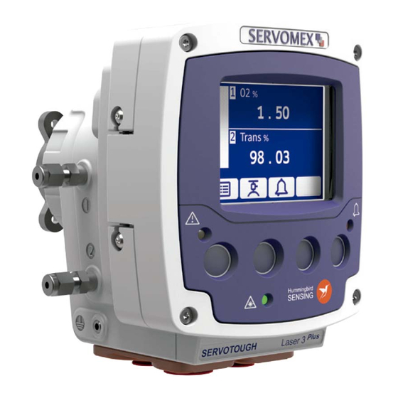
Servomex SERVOTOUGH Laser 3 Plus Operator's Manual (221 pages)
Brand:
Servomex
| Category:
Measuring Instruments
| Size: 9 MB
Table of Contents
Table of Contents
5
Safety
15
General Warnings and Cautions
15
Laser Safety
16
Certification
16
Markings
18
Figure 1-1: Laser 3 Plus Transmitter Unit Rating Label Location
18
Figure 1-2: Laser 3 Plus Receiver Unit Certification Label Location
18
Figure 1-3: Laser 3 Plus Transmitter Unit Certification Label
19
Figure 1-4: Laser 3 Plus Receiver Unit Laser Label Location
19
Figure 1-5: Laser 3 Plus Transmitter Unit Laser Label Location
20
Figure 1-6: Laser 3 Plus Mount Laser Label Location
20
Introduction
21
Product Description
21
Figure 2-1: Laser 3 Plus Example Installation (Exploded View)
21
Figure 2-2: Laser 3 Plus Installation: Showing Thermal Spacer and Isolation Flange Options
22
Transmitter Unit
23
Figure 2-3: Transmitter Unit: Front, Rear, Side and Under-Side Views
23
Receiver Unit
25
Figure 2-4: Receiver Unit: Front, Rear, Side and Under-Side Views
25
Figure 2-5: Receiver Unit Indicators
26
Mounting Assembly (Flange and Window Purge)
27
Power Supply (Optional)
27
Product Specifications
27
Figure 2-6: Transmitter Unit Dimensions
27
Figure 2-7: Receiver Unit Dimensions
28
Additional Information
30
Materials in Contact with the Sample
33
Unpacking
33
Transmitter User Interface
34
Keypad
34
Transmitter Unit Indicator Leds
34
Figure 3-1: Transmitter Pushbutton Keys, Screen Icons and Indicator Leds
34
Start-Up Screen
35
Measurement Screen
35
Figure 3-2: Start up Screen
35
Figure 3-3: Example of a 'Live' Measurement Screen
35
Figure 3-4: Example of Second Measurement Screen
36
Figure 3-5: Example of an 'Invalid' Measurement Screen
36
Soft Key Legends
37
System and Measurement Status Icons
38
Navigating the Analyzer User Interface
38
Menu Structure
40
Figure 3-6: Top Level Menu Structure
40
Edit On-Screen Data
41
Figure 3-7: Edit Screen
41
Password Protection
42
Configuration Setting
43
Figure 3-8: Saving Sensor Measurement (Detailed) Settings
45
Figure 3-9: Restore Measurement (Detailed) Settings
46
Figure 3-10: Save Current Calibration Configuration
47
Figure 3-11: Restore Configuration Settings
48
Figure 3-12: Save/ Load Analyzer (Non-Sensor) Configuration Menu
49
Figure 3-13: Save a Support Package
51
Configuration
52
User Settings
52
Figure 4-1: Network Settings Sequential Menu
52
Figure 4-2: Set Time and Date Menu
53
Figure 4-3: Regional Settings Sequential Menu
54
Figure 4-4: Upper and Lower Display Block Menu
55
Figure 4-5: Screen Backlight Time Menu
56
Figure 4-6: Screen Brightness Menu
57
Configure Ma Inputs
58
Figure 4-7: Select Ma Input
58
Figure 4-8: Enable or Disable Ma Input
58
Figure 4-9: Ma Input Sequential Menu
59
Settings Related to Process Conditions "Physical Set-Up
61
Figure 4-10: Physical Setup Sequential Menu
61
Configure Ma Outputs
64
Figure 4-11: Ma Output Sequential Menu
65
Figure 4-12: Ma Output Selection Menu
65
Figure 4-13: Ma Output Range Selection Menu
66
Figure 4-14: Ma Output Calibration and Override Menu
68
Configure Measurement Alarms
69
Figure 4-15: View Active Measurement Alarm Status Menu
69
Figure 4-16: Select Alarm Menu
70
Figure 4-17: Assign Alarm Menu
70
Figure 4-18: Select Alarm Mode Menu
71
Figure 4-19: Select Alarm Latching Mode Menu
72
Figure 4-20: Set Alarm Level and Hysteresis Menu
73
Configure Relay Outputs
74
Figure 4-21: Set Alarm Follow Menu
74
Figure 4-22: Alarm History Menu
74
Figure 4-23: Relay Output Selection Menu
75
Figure 4-24: Relay Output Configuration Menu
75
Figure 4-25: Relay Coil State Menu
78
Filtering
79
Unit Select
79
Figure 4-26: Filtering Configuration Menu
79
Figure 4-27: Set up Units Menu
80
X-Interference Offset
81
Clipping
81
Figure 4-28: X - Interference Configuration Menu
81
Figure 4-29: Set up Clipping Menu
81
Figure 4-30: Clipping Configuration Menu
82
Gain and Phase Settings
83
Figure 4-31: Gain and Phase Setting Menu
83
Figure 4-32: Adjust Gain and Phase Menu
84
Figure 4-33: Raw Signal Graph Example
85
General Analyzer Information
87
Status
87
Figure 5-1: Status Sequential Menu
87
Measurement
88
Figure 5-2: Measurement Menu
88
Data Log
89
Figure 5-3: Data Log Sequential Menu
89
Figure 5-4: Adjust Data Log Menu
91
Figure 5-5: Micro SD Connector
93
Saturation
94
Drift
95
Calibration
96
Save the Configuration Settings
96
Table 6-1: Calibration Check List
96
Removing the Transmitter and Receiver Units from the Process
97
Remove the Transmitter and Receiver Units from the Process
97
Connecting Transmitter and Receiver Units to the Calibration Cell
98
Figure 6-1: Offline Calibration View
98
Reconfigure Settings for Off-Line Calibration
100
Reconfigure Settings for Offline Calibration
100
Figure 6-2: Physical Setup Sequential Menu
100
Saving the Measurement Sensor and Environmental Calibration Settings
101
Calibration Settings
101
Figure 6-3: Measurement Sensor and Environmental Configuration Menu
101
Figure 6-4: Calibration Settings Menu
101
Calibrate
103
Saving Calibration Configuration
105
Figure 6-5: Save Calibration Configuration Menu
105
Restore Configuration Settings
106
View Calibration History
106
Dependent Measurement Calibration
106
Figure 6-6: Restore Physical Configuration Menu
106
Figure 6-7: View Calibration History
106
In-Situ Validation (In-Line Gas Validation)
107
Automatic In-Situ Validation
119
Installation
136
Installation Preparations
136
Table 7-1: Pre-Installation Check List
136
Figure 7-1: Laser 3 Plus Installation Distances
138
Figure 7-2: Laser 3 Plus Flange Dimensions
140
Figure 7-3: Process Flange Bolt Arrangement (4 Bolt Pattern)
141
Figure 7-4: Process Flange Positioning Tolerance
142
Figure 7-5: Transmitter Unit Mounting Arrangement (Example Shown with Adjustable Mount)
143
Figure 7-6: Receiver Unit Mounting Arrangement (Example Shown with Fixed Mount)
144
Installation Overview
145
Figure 7-7: Installation Overview
145
Figure 7-8: Laser 3 Plus In-Situ Installation
147
Table 7-2: Pre-Installation Check List
147
Process Connections
148
Figure 7-9: Example of Mounting / Alignment Assembly Fitting Exploded View
149
Figure 7-10 Alignment Tool
151
Figure 7-11: Align M6 Screws with the Flange Joint
152
Figure 7-12: Rotate the Enclosure
153
Figure 7-13: Tighten the M6 Screws
153
Electrical Connections
154
Figure 7-14: Cable Strip Lengths
156
Figure 7-15: Receiver Unit Cable Gland Position
156
Functional Earth / Ground Requirements
157
Figure 7-16: Transmitter Unit Cable Gland Positions
157
Figure 7-17: Opening the Transmitter Unit
159
Figure 7-18: 7-Way Main Terminal and Entry Glands
160
Figure 7-19: 8-Way Transmitter to Receiver Connector
161
Figure 7-20: Ethernet Connections
163
Figure 7-21: 12-Way Options Board Connections
164
Purge Connections
165
Figure 7-22: Transmitter Purge
166
Figure 7-23: Receiver Purge
167
Commissioning
169
Table 7-3: Mechanical Installation Check List
169
Table 7-4: Alignment Check List
170
Figure 7-24: Peel Back the Boot
171
Figure 7-25: Installation: Ball-Joint Adjustment Screws
172
Figure 7-26: Installation: Large O-Ring Adjustment Screws
173
Figure 7-27: Installation: Large O-Ring Initial Setting
173
Figure 7-28: Installation: Large O-Ring Compression Check
174
Figure 7-29: Installation: Adjust Laser Intensity on the Photodiode
175
Table 7-5: Software Configuration Check List
176
Table 7-6: Measurement Configuration Check List
176
Service
177
Service Functions
177
Figure 8-1: Ma Override Menu
177
Figure 8-2: Ma Output Calibration Menu
177
Figure 8-3: Ma Input Menu
178
Figure 8-4: Relay Override Menu
179
Figure 8-5: Service Override Menu
179
Routine Maintenance
180
Cleaning
181
Routine Checks
181
Figure 8-6: Optical Windows
181
Alignment / Purging Flanges
182
Enclosure Purge and Breather (if Fitted)
182
User Replaceable Spare Parts
182
Certification Information 169 9.1 Hazardous Area Approval and Certification
183
Label Information
185
Figure 9-1: ATEX / Iecex Labels
185
Figure 9-2: SGS North American Labels
185
Figure 9-3: Rating Label
185
Emc
186
Electrical Safety
186
Product Disposal
186
EU REACH Regulations
187
Index
188
Appendix Display Unit Conversion
190
Appendix Modbus Setup
191
Implementation Guide for Modbus Communications
191
Appendix French Translation of Warnings
201
General Warnings and Cautions
201
Laser Safety
203
Certification
203
Hazardous Area Installations
203
Hazardous Area Variants
205
Raw Signal Graph
206
1SD Card
206
Removing the Transmitter and Receiver Units from the Process
207
Installation Preparations
210
Items to Remove before Installation
210
Analyzer Placement
210
Process Flanges
211
Mounting Rigidity
212
Installation Overview
212
Safety
213
Process Connections
214
Fitting the Transmitter and Receiver Mounting/ Alignment Assembly
214
Alignment of the Transmitter and Receiver Mounting / Alignment Assemblies
214
Fitting the Transmitter and Receiver on the Flange
215
Electrical Connections
216
General Safety
216
Glands and Cable Entries
217
Functional Earth / Ground Requirements
218
Power Cable Connections
218
Identification and Location of Electrical Terminals
218
Advertisement
Advertisement
Related Products
Servomex SERVOTOUGH Oxy
Servomex SERVOTOUGH LaserSPII mini
Servomex SERVOTOUGH SpectraExact 2500 Series
Servomex SERVOTOUGH LaserExact 2950
Servomex Servotough SpectraScan 2400
Servomex SERVOTOUGH OxyExact 2200 Series
Servomex SERVOTOUGH Laser SP 2930
Servomex SERVOTOUGH SpectraExact 2500
Servomex 01440002D
Servomex 07931001B
Servomex Categories
Measuring Instruments
Analytical Instruments
Transmitter
Industrial Equipment
More Servomex Manuals
Login
Sign In
OR
Sign in with Facebook
Sign in with Google
Upload manual
Upload from disk
Upload from URL