Sign In
Upload
Manuals
Brands
Optimum Manuals
Power Tool
OPTImill MH 50G
Optimum OPTImill MH 50G Manuals
Manuals and User Guides for Optimum OPTImill MH 50G. We have
2
Optimum OPTImill MH 50G manuals available for free PDF download: Operating Manual
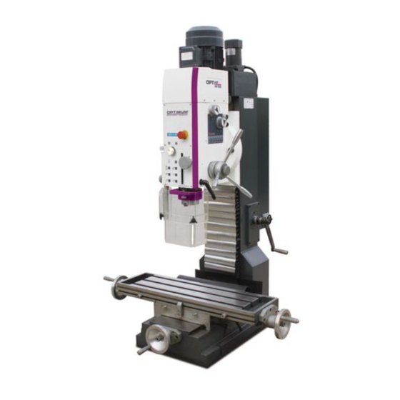
Optimum OPTImill MH 50G Operating Manual (142 pages)
Brand:
Optimum
| Category:
Power Tool
| Size: 3.97 MB
Table of Contents
Table of Contents
2
Sicherheit
8
Typschilder
8
Sicherheitshinweise (Warnhinweise)
9
Gefahren-Klassifizierung
9
Weitere Piktogramme
9
Bestimmungsgemäße Verwendung
10
Vernünftigerweise Vorhersehbare Fehlanwendung
11
Vermeidung von Fehlanwendungen
11
Gefahren die von der Fräsmaschine Ausgehen können
13
Qualifikation
14
Private Nutzer
14
Pflichten des Nutzers
14
Handwerklicher oder Industrieller Einsatz
14
Autorisierte Personen
15
Pflichten des Betreibers
15
1.6.6 Pflichten des Bedieners
16
Zusätzliche Anforderungen an die Qualifikation
16
Bedienerpositionen
16
Sicherheitsmaßnahmen während des Betriebs
16
Sicherheitseinrichtungen
16
NOT-Halt Schalter
17
Hauptschalter Abschließbar
17
Gespeicherte Ladungen an MH50V
18
Trennende Schutzvorrichtung
18
Sicherheitsüberprüfung
18
Körperschutzmittel
19
Zu Ihrer Eigenen Sicherheit während des Betriebs
19
Abschalten und Sichern der Fräsmaschine
20
1.13.1 Hauptschalter Abschließbar
20
Verwenden von Hebezeugen
20
Symbole an der Fräsmaschine
20
Elektrik
20
Prüffristen
21
Technische Daten
22
Elektrischer Anschluß
22
Fräsleistung
22
Spindelaufnahme
22
Bohr- Fräskopf
23
Kreuztisch
23
Abmessungen
23
Arbeitsraum
23
Drehzahlen
23
Umgebungsbedingungen
23
Betriebsmittel
24
Emissionen
24
Werkzeuge und Werkzeugaufnahmen
25
Anlieferung, Innerbetrieblicher Transport, Montage und Inbetriebnahme
26
Hinweise zu Transport, Aufstellung, Inbetriebnahme
26
Allgemeine Gefahren Beim Innerbetrieblichen Transport
26
Auspacken der Maschine
27
Aufstellen und Montieren
27
Anforderungen an den Aufstellort
27
Lastanschlagstelle
27
3.3.3 Montieren
28
Abmessungen, Schwerpunkt
29
Montage auf dem Optional Erhältlichen Maschinenunterbau
31
Erste Inbetriebnahme
32
Reinigen und Abschmieren
32
Elektrischer Anschluss
33
MH50G und MH50V
33
Mh50V
33
Geregelte Antriebe in Verbindung mit Fehlerstrom-Schutzeinrichtungen
34
Schutz gegen Gefährliche Körperströme, Anwendung von FI-Schutzschaltern
34
Strom IM Schutzerdungsleiter - Ableitstrom
34
Auslösens des FI-Schutzschalters
35
Bedienung
36
Bedien- und Anzeigeelemente
36
Bedienpanel
37
Sicherheit
38
Fräsmaschine Einschalten
38
Fräsmaschine Ausschalten
38
Zurücksetzen eines Not-Halt Zustands
38
Energieausfall, Wiederherstellen der Betriebsbereitschaft
38
Drehzahleinstellung
38
Drehzahltabelle MH50G ( ~50Hz Anschluss )
39
Drehzahltabelle MH50V
39
Wahl der Drehzahl
39
Getriebestufe
39
Spindeldrehrichtung
39
Vorschub
40
Pinolenvorschub
40
4.10.1 Bohr- oder Gewindetiefe Einstellen - Signalton Einstellen
40
Gewinde Bohren
41
Eilgang Fräskopf
41
Werkzeug Einsetzen oder Ausbauen
42
4.13.1 Einbau
42
4.13.2 Ausbau
42
Spannen der Werkstücke
42
4.14.1 Berechnung der Schnittkräfte Bzw. der Notwendigen Spannkraft Beim Fräsen
43
Fräskopf Schwenken
44
Instandhaltung
45
Sicherheit
45
Vorbereitung
45
Wiederinbetriebnahme
45
Inspektion und Wartung
45
Instandsetzung
48
Kundendiensttechniker
48
Störungen
49
Störungen an der Fräsmaschine
49
Anhang
51
Urheberrecht
51
Terminologie/Glossar
51
Änderungsinformationen Betriebsanleitung
51
Mangelhaftungsansprüche / Garantie
52
Entsorgungshinweis / Wiederverwertungsmöglichkeiten
52
Lagerung
53
Abbauen, Demontieren, Verpacken und Verladen
53
Außerbetrieb Nehmen
54
Abbauen
54
Demontieren
54
Verpacken und Verladen
54
Entsorgung der Neugeräte-Verpackung
54
Entsorgung der Schmiermittel und Kühlschmierstoffe
54
Entsorgung über Kommunale Sammelstellen
55
Produktbeobachtung
55
Safety
59
Rating Plates
59
Safety Instructions (Warning Notes)
60
Classification of Hazards
60
Other Pictograms
60
Intended Use
61
Reasonably Foreseeable Misuse
62
Avoiding Misuse
62
Possible Dangers Posed by the Milling Machine
64
Qualification
65
Private Users
65
Obligations of the User
65
Craftsman or Industrial Use
65
Authorized Personnel
66
Operator's Obligations
66
Obligations of the Operator
66
Additional Requirements Regarding Qualification
66
User Positions
67
Safety Measures During Operation
67
Safety Devices
67
Emergency Stop Button
67
Lockable Master Switch
68
Stored Charge on MH50V
68
Separation Guard
69
Safety Check
69
Personal Protective Equipment
70
For Your Own Safety During Operation
70
Switching-Off and Securing the Milling Machine
70
1.13.1 Lockable Main Switch
70
Using Lifting Equipment
71
Symbols on the Milling Machine
71
Electronics
71
Inspection Deadlines
71
Technical Data
72
Electrical Connection
72
Milling Capacity
72
Spindle Seat
72
Drill-Mill Head
73
Cross Table
73
Dimensions
73
Work Area
73
Speeds
73
Environmental Conditions
73
Operating Material
74
Emissions
74
Tools and Tool Holding Fixtures
75
Delivery, Interdepartmental Transport, Assembly and Commissioning
76
Notes on Transport, Installation, Commissioning
76
General Risks During Internal Transport
76
Unpacking the Machine
77
Installation and Assembly
77
Installation Site Requirements
77
Load Suspension Point
77
Assembly
77
Dimensions, Balance Point
79
Mounting on the Optionally Available Machine Base
81
First Commissioning
82
Cleaning and Lubrication
82
Electrical Connection
83
MH50G and MH50V
83
Mh50V
83
Regulated Drives in Connection with Residual Current Devices
84
Protection from Dangerous Shock Currents, Use of Elcbs
84
Current in the Protective Earth Conductor - Leakage Current
84
When the ELCB Triggers
85
Operation
86
Control and Indicating Elements
86
Control Panel
87
Safety
88
Switching the Milling Machine on
88
Switching the Milling Machine off
88
Resetting an Emergency Stop Situation
88
Power Failure, Restoring Readiness for Operation
88
Speed Setting
88
Speed Table MH50G ( ~50Hz Connection )
89
Speed Table MH50G ( ~60Hz Connection )
89
Speed Table MH50V
89
Selecting the Speed
89
Gear Stage
89
Direction of Spindle Rotation
89
Feed
90
Spindle Quill Feed
90
4.10.1 Setting the Drilling or Tapping Depth - Setting the Beep
90
Tapping
91
Milling Head Rapid Traverse
91
Inserting or Removing Tool
92
4.13.1 Inserting
92
4.13.2 Removing
92
Clamping the Workpieces
92
4.14.1 Calculation of the Cutting Forces or Necessary Holding Force When Milling
93
Swivelling the Milling Head
94
Maintenance
95
Safety
95
Preparation
95
Restarting
95
Inspection and Maintenance
95
Repair
98
Customer Service Technician
98
Malfunctions
99
Milling Machine Malfunctions
99
Appendix 7.1 Copyright
100
Terminology/Glossary
100
Change Information Operating Manual
100
Liability Claims/Warranty
101
Advice for Disposal / Options of Reuse
101
Storage
102
Dismantling, Disassembling, Packing and Loading
102
Decommissioning
103
Dismantling
103
Disassembly
103
Packing and Loading
103
Disposal of New Device Packaging
103
Disposal of Lubricants and Cooling Lubricants
103
Disposal Via Municipal Collection Facilities
104
Product Follow-Up
104
Ersatzteile - Spare Parts
107
Ersatzteilbestellung - Ordering Spare Parts
107
Hotline Ersatzteile - Spare Parts Hotline
107
Service Hotline
107
Ersatzteilzeichnungen - Spare Part Drawings
108
Schaltplan - Wiring Diagram - MH50G
123
Schaltplan - Wiring Diagram - Integrated Machine Control - MH50G
128
Schaltplan - Wiring Diagram - MH50V
133
Advertisement
Optimum OPTImill MH 50G Operating Manual (76 pages)
Brand:
Optimum
| Category:
Power Tool
| Size: 2.78 MB
Table of Contents
Table of Contents
2
1 Safety
6
Type Plates
6
Safety Instructions (Warning Notes)
7
Classification of Hazards
7
Other Pictograms
7
Intended Use
8
Reasonably Foreseeable Misuse
9
Avoiding Misuse
9
Possible Dangers Posed by the Milling Machine
10
Qualification
11
Private Users
11
Obligations of the User
11
Craftsman or Industrial Use
11
Authorized Personnel
12
Operator's Obligations
12
Obligations of the Operator
12
Additional Requirements Regarding Qualification
13
User Positions
13
Safety Measures During Operation
13
Safety Devices
13
Emergency Stop Button
14
Lockable Master Switch
14
Stored Charge on MH50V
14
Separation Guard
15
Safety Check
15
Personal Protective Equipment
16
For Your Own Safety During Operation
16
Switching-Off and Securing the Milling Machine
16
Lockable Main Switch
16
Using Lifting Equipment
17
Symbols on the Milling Machine
17
Electronics
17
Inspection Deadlines
17
2 Technical Data
18
Electrical Connection
18
Milling Capacity
18
Spindle Seat
18
Drill-Mill Head
19
Cross Table
19
Dimensions
19
Work Area
19
Speeds
19
Environmental Conditions
19
Operating Material
20
Emissions
20
Tools and Tool Holding Fixtures
21
3 Unpacking and Connecting
22
Unpacking the Machine
22
Transport
22
Installation and Assembly
22
Installation Site Requirements
22
Load Suspension Point
23
Assembly
23
Dimensions, Balance Point
24
Mounting on the Optionally Available Machine Base
26
First Commissioning
27
Cleaning and Lubrication
28
Electrical Connection
28
MH50G and MH50V
28
Mh50V
29
Regulated Drives in Connection with Residual Current Devices
30
Protection from Dangerous Shock Currents, Use of Elcbs
30
Current in the Protective Earth Conductor - Leakage Current
30
When the ELCB Triggers
31
4 Operation
32
Control and Indicating Elements
32
Control Panel
33
Safety
34
Switching the Milling Machine on
34
Switching the Milling Machine off
34
Resetting an Emergency Stop Situation
34
Power Failure, Restoring Readiness for Operation
34
Speed Setting
34
Selecting the Speed
34
Gear Stage
35
Direction of Spindle Rotation
35
Feed
35
Spindle Quill Feed
36
Setting the Drilling or Tapping Depth
36
Tapping
36
Milling Head Rapid Traverse
37
Inserting or Removing Tool
37
Inserting
37
Removing
38
Clamping the Workpieces
38
Calculation of the Cutting Forces or Necessary Holding Force When Milling
39
Swivelling the Milling Head
39
5 Maintenance
40
Safety
40
Preparation
40
Restarting
40
Inspection and Maintenance
40
Repair
43
Customer Service Technician
43
6 Ersatzteile - Spare Parts
44
Fräskopf - Milling Head 1 - 4
44
Fräskopf - Milling Head 2 - 4
44
Fräskopf - Milling Head 3 - 4
45
Fräskopf - Milling Head 4 - 4
45
Säule - Column 1 - 2
48
Säule - Column 2 - 2
49
Kreuztisch - Cross Table 1 - 2
50
Kreuztisch - Cross Table 2 - 2
50
Schutzeinrichtung - Protection Device
52
Schaltschrank - Switch Cabinet
52
Schaltplan - Wiring Diagram - MH50G
57
Schaltplan - Wiring Diagram - MH50V
60
7 Malfunctions
67
Milling Machine Malfunctions
67
8 Appendix 8.1 Copyright
68
8 Appendix
68
Change Information Operating Manual
68
Terminology/Glossary
68
Advice for Disposal / Options of Reuse
69
Liability Claims/Warranty
69
Dismantling, Disassembling, Packing and Loading
70
Decommissioning
71
Dismantling
71
Disassembly
71
Packing and Loading
71
Storage
70
Disposal of Lubricants and Cooling Lubricants
71
Disposal of New Device Packaging
71
Disposal Via Municipal Collection Facilities
72
Product Follow-Up
72
Advertisement
Related Products
Optimum OPTImill MH 50V
Optimum OPTIMILL MH 28V
Optimum OPTImill MH 25V
Optimum OPTimill MH 35G
Optimum OPTimill MH 35V
Optimum OPTImill MH 22V
Optimum OPTImill MH 22VD
Optimum OPTimill MH 25 SV
Optimum Optimill MH 20V
Optimum Optimill MH 20VL
Optimum Categories
Kettle
Drill
Kitchen Appliances
Blender
Power Tool
More Optimum Manuals
Login
Sign In
OR
Sign in with Facebook
Sign in with Google
Upload manual
Upload from disk
Upload from URL