Sign In
Upload
Manuals
Brands
Opticon Manuals
Barcode Reader
OPI 2201
Opticon OPI 2201 Manuals
Manuals and User Guides for Opticon OPI 2201. We have
1
Opticon OPI 2201 manual available for free PDF download: Specification Manual
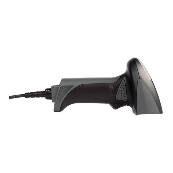
OPTICON OPI 2201 Specification Manual (59 pages)
Imager Scanner OPI 2201
Brand:
OPTICON
| Category:
Barcode Reader
| Size: 3 MB
Table of Contents
Document History
2
Serial Number
2
Table of Contents
3
1 Abstract
8
2 Overview
8
Supported Symbologies
9
3 Physical Features
10
Dimensions
10
Weight
10
4 Environmental Specifications
10
Operating Temperature and Humidity
10
Storage Temperature and Humidity
10
Ambient Light Immunity
10
Figure 1: Ambient Light Immunity
11
5 Controls
12
6 Electrical Specifications
12
Configuration
12
Figure 2: Electrical Configuration
12
Absolute Maximum Ratings
13
Recommended Operating Conditions
13
Electrical Characteristics
13
AC Adaptor Specifications
13
Input Specifications
13
Output Specifications
14
7 Optical Specifications
14
Imager Scanning
14
Imager Output
15
8 Technical Specifications
15
Print Contrast Signal (PCS)
17
Minimum Resolution
17
Scan Area and Resolution
18
Depth of Field
18
Figure 3: Depth of Field
18
Pitch, Skew, and Tilt
20
Pitch Angle
20
Skew Angle and Dead Zone
20
Tilt Angle
20
Figure 4: Pitch, Skew, and Tilt
20
Curvature
21
Scanning Barcodes on Moving Items
21
Figure 5: Curvature
21
Horizontal Motion Tolerance
22
9 Interface Specifications
22
RS-232C Interface Spec
22
Settings and Communication
22
Figure 6: Horizontal Motion
22
Signal Level
23
Interface Circuit
23
Character Format
23
Figure 7: RS-232C Interface Circuit
23
Figure 8:Character Format
23
Communication Format
24
Handshaking
24
Figure 9: Communication Format
24
Figure 9: no Handshaking
24
Figure 11: Busy/Ready Communication
24
Figure 12: Cannot Receive Command
25
Figure 13: Signal Timing
25
Figure 14: Modem Transmit Data
26
Figure 15: ACK/NAK
27
Figure 16: ACK/NAK-No Response
28
USB-HID and USB-VCP Interface Specifications
29
Settings
29
Interface Specification
29
Circuit
29
Wedge Interface Specification
29
Figure 17: USB Interface Circuit
29
10 Cable and Connector
30
RS-232C Cable
30
Connectors
30
Figure 18: RS-232C Cable
30
Figure 19: DB 9 Connector
30
Pin Assignment
31
USB Cable
32
Connector
32
Pin Assignment
32
Figure 20: USB Cable
32
Figure 21: USB "A" Connector
32
Wedge Cable
33
Figure 22: Wedge Interface Cable
33
Figure 23: Wedge Branch Cable
33
Connectors
34
Figure 24: Wedge Connector
34
Figure 25: Front View
34
Pin Assignment
34
11 Default Settings
35
Set Default Interface
35
Figure 26: Front View
35
Default Settings 1: Readable Codes
37
Default Settings 2: Read Options, Trigger, Buzzer
39
Default Settings 3: Serial Communication Settings-RS-232C
39
Default Settings 3A: Serial Communication Settings-RS-232C
39
Default Settings 3B: Serial Communication Settings-RS-232C
39
Default Settings 4: Keyboard Communication Settings-Wedge
40
Default Settings 5: Keyboard Communication Settings-USB-HID, USB-VCP
40
12 Serial Number and Labeling
41
Figure 27: Serial Number Diagram
41
13 Packaging Specifications
42
Individual Packaging Specification
42
Accessory Specifications
42
Figure 28: Individual Packaging
42
Collective Packaging Specification
43
Figure 29: Collective Packaging
43
14 Durability
44
Electrical Noise
44
Static Electricity
44
Shock
44
Drop Test (Without Packaging)
44
Figure 30: Drop Test
44
Drop Test (with Individual Packaging)
45
Vibration Strength
45
Dust and Drip Proof
45
Cable Strength
45
Cable Bending Test
45
15 Reliability
46
Figure 31: Cable Strength
46
16 Trigger and Read Options
47
Trigger Modes
47
Read Modes
47
Auto Trigger Options
48
Auto Trigger Overview
48
Figure 32: Auto Trigger Detection Area
48
Figure 33: Auto Trigger Specifications
48
Image Capture Options
49
17 Trigger and Read Settings
50
Read Time Settings
50
Read Time
50
Multiple Read Reset Time
51
Auto Trigger Settings
52
Enable/Disable Settings
52
Auto Trigger Sensitivity Settings
53
Setting Image Capture Mode
54
Configuring Gamma Values
55
18 Regulatory Compliance
56
Laser / LED Safety
56
LED Safety
56
Emc
56
Rohs
56
19 Safety
57
Shock
57
Temperature Conditions
57
Foreign Materials
57
Other
57
20 Mechanical Drawing
58
Figure 34: Mechanical Drawing
58
21 Detailed View of the AC Adapter
59
Figure 35: AC Adapter (for Input Side)
59
Figure 36: AC Adapter (for Output Side: DC Jack)
59
Advertisement
Advertisement
Related Products
Opticon OPI-3601
Opticon OPI 4002
Opticon OPI 2002
Opticon OPL972X
Opticon OPL 9712
Opticon OPR3301
Opticon OPN2005
Opticon OPR 3201
Opticon OPH 1004
Opticon OPR 3101
Opticon Categories
Barcode Reader
Scanner
Handhelds
Touch terminals
Telescope
More Opticon Manuals
Login
Sign In
OR
Sign in with Facebook
Sign in with Google
Upload manual
Upload from disk
Upload from URL