Sign In
Upload
Manuals
Brands
Omron Manuals
Inverter
SYSDRIVE 3G3MV-AB015
Omron SYSDRIVE 3G3MV-AB015 Manuals
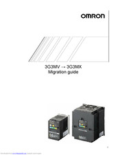
Manuals and User Guides for Omron SYSDRIVE 3G3MV-AB015. We have
3
Omron SYSDRIVE 3G3MV-AB015 manuals available for free PDF download: User Manual, Migration Giude
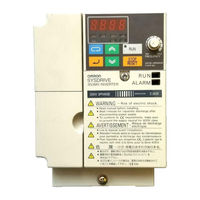
Omron SYSDRIVE 3G3MV-AB015 User Manual (344 pages)
SYSDRIVE 3G3MV Series Multi-function Compact Inverter
Brand:
Omron
| Category:
Inverter
| Size: 2.48 MB
Table of Contents
General Precautions
6
Wiring Precautions
7
Checking before Unpacking
11
Checking the Accessories
12
Dimensions and Weights
15
About this Manual
16
Table of Contents
19
Chapter 1. Overview
23
Functions
24
Chapter 1 Overview
26
Nomenclature
27
Digital Operator
28
New Features
30
Chapter 2. Design
33
Installation
34
Dimensions
34
Installation Conditions
38
Removing and Mounting the Covers
40
Removing the Terminal Cover
41
Removing the Bottom Cover
42
Wiring
43
Terminal Block
44
Main Circuit Terminals
46
Control Circuit Terminals
47
Standard Connections
52
Wiring Around the Main Circuit
53
Ground Wiring
61
Wiring Control Circuit Terminals
66
Conforming to EC Directives
68
Chapter 3. Preparing for Operation and Monitoring
75
Nomenclature
76
Names of Parts and Their Functions
76
Outline of Operation
78
Parameter Copy and Verify Function
84
Parameter for Copying and Verifying Set Values
84
Parameter Copying Procedure
85
Parameter Read-Prohibit Selection
91
Parameter Copy or Verify Errors
92
Chapter 4. Test Run
93
Procedure for Test Run
95
Operation Example
97
Test Run
98
Initializing Parameters
98
Actual Load Operation
100
Chapter 5. Basic Operation
103
Initial Settings
104
Setting the Parameter Write-Prohibit Selection/Parameter Initialization (N001)
104
Setting the Control Mode (N002)
105
Basic Operation
106
Operation in Vector Control
107
Operation in V/F Control
109
Setting the Rated Motor Current (N036)
109
Setting the V/F Patterns (N011 to N017)
109
Setting the Local/Remote Mode
111
Selecting the Operation Command
112
Setting the Frequency Reference
113
Selecting the Frequency Reference
113
Upper and Lower Frequency Reference Limits
114
Frequency Referencing by Analog Input
115
Setting Frequency References through Key Sequences
120
Setting Frequency References by Pulse Train Input
125
Setting the Acceleration/Deceleration Time
127
Selecting the Reverse Rotation-Prohibit
130
Selecting the Stopping Method
131
Multi-Function I/O
132
Multi-Function Input
132
Multi-Function Output
138
Multi-Function Analog Output and Pulse Monitor Output
140
Setting the Multi-Function Analog Output (N065 through N067)
140
Setting the Pulse Monitor Output (N065 and N150)
141
Chapter 6. Advanced Operation
143
Precise Vector Control Settings and Adjustments
144
Precise Vector Control Settings
144
Adjusting Output Torque in Vector Control
145
Energy-Saving Control
147
Energy-Saving Control Operation
147
Performing Energy-Saving Settings
148
PID Control
153
PID Control Applications
153
PID Control Operation
154
Types of PID Control
154
Block Diagram of PID Control
156
Input Selection of PID Control Target Value and Detection Value
157
PID Control Settings
158
PID Adjustments
161
PID Fine Tuning
163
Setting the Carrier Frequency
165
DC Injection Braking Function
168
Stall Prevention Function
169
Overtorque/Undertorque Detection Function
173
Torque Compensation Function
177
Slip Compensation Function
179
Other Functions
181
Digital Operator Disconnection Error Detection
181
Motor Protection Functions (N037 and N038)
181
Cooling Fan Operation Function (N039)
182
Momentary Power Interruption Compensation (N081)
182
Fault Retry (N082)
183
Frequency Jump Function (N083 to N086)
184
Accumulated Operating Time (N087, N088)
185
Frequency Detection
186
UP/DOWN Command Frequency Memory (N100)
187
Input Open-Phase Detection (N166, N167)
189
Output Open-Phase Detection (N168, N169)
189
Fault Log (N178)
190
Chapter 7. Communications
191
Inverter Settings
192
Setting the Communications Conditions
192
RUN Command Selection (N003)
195
Frequency Reference Input Selection (N004)
196
Setting the Multi-Function Inputs (N050 to N056)
196
Message Communications Basic Format
198
Slave Address
199
Function Code
199
Error Check
200
DSR Message and Response
201
Data Read (Function Code: 03 Hex)
201
Data Write/Broadcast Data Write (Function Code: 10 Hex)
203
Loop-Back Test (Function Code: 08 Hex)
206
Enter Command
208
Setting the Communications Data
209
Register Number Allocations in Detail
211
I/O Function
211
Monitor Functions
212
Communications Error Codes
217
Self-Diagnostic Test
219
Communications with Programmable Controller
220
Available Programmable Controllers and Peripheral Devices
220
Peripheral Devices
221
Wiring the Communications Line
223
Outline of Protocol Macro Function
224
Creating a Project File
228
Ladder Program
237
Communications Response Time
241
Chapter 8. Maintenance Operations
243
Protective and Diagnostic Functions
244
Fault Detection (Fatal Errors)
244
Warning Detection (Nonfatal Errors)
252
Troubleshooting
256
Parameters Fail Set
256
Motor Fails to Operate
256
Motor Rotates in the Wrong Direction
258
Motor Outputs no Torque or Acceleration Is Slow
258
Speed Accuracy of the Inverter Rotating at High Speed in Vector Control Is Low
259
Motor Deceleration Rate Is Low
259
Vertical-Axis Load Drops When Brakes Are Applied
259
Motor Burns
260
Controller or am Radio Receives Noise When Inverter Is Started
260
Ground Fault Interrupter Is Actuated When Inverter Is Started
260
Mechanical Vibration
261
Stable PID Control Is Not Possible or Control Fails
261
Inverter Vibration in Energy-Saving Control
262
Motor Rotates after Output of Inverter Is Turned off
262
Detects OV (over Voltage) and Stalls When Motor Starts
262
Output Frequency Does Not Reach Frequency Reference
263
Inverter Does Not Run Because EF
263
Simultaneous Inputs of Forward and Reverse Commands) Is Detected or Motor Rotates Momentarily When Control Device Power Is Turned off
263
Maintenance and Inspection
264
Replacement of Cooling Fan
265
Chapter 9. Specifications
269
Inverter Specifications
270
Specifications
271
Option Specifications
275
List of Options
275
Devicenet Communications Unit
277
Fan Unit
278
Scaling Meter
279
Braking Resistor
280
Braking Resistor Unit
282
DC Reactor
283
DIN Track Mounting Bracket
284
Digital Operators
285
AC Reactor
288
EMC-Compatible Noise Filter
290
Connection Example
291
External Dimensions
292
Simple Input Noise Filter and Input Noise Filter
298
Output Noise Filter
300
Chapter 10. List of Parameters
303
Chapter 11. Using the Inverter for a Motor
337
Synchronous Motor
339
Revision History
341
Advertisement
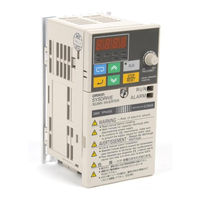
Omron SYSDRIVE 3G3MV-AB015 User Manual (348 pages)
Multi-function Compact Inverter SYSDRIVE 3G3MV Series
Brand:
Omron
| Category:
Inverter
| Size: 2.75 MB
Table of Contents
Checking before Unpacking
3
Installation Precautions
8
Wiring Precautions
8
General Precautions
9
Table of Contents
11
Chapter 1. Overview
15
Function
16
Nomenclature
19
Digital Operator
20
New Features
22
Chapter 2. Design
24
Installation
25
Dimensions
25
Installation Conditions
29
Removing and Mounting the Covers
31
Removing the Front Cover
31
Removing the Digital Operator
33
Wiring
34
Terminal Block
35
Main Circuit Terminals
37
Control Circuit Terminals
38
Standard Connections
43
Wiring Around the Main Circuit
44
Installing a Magnetic Contactor
49
Wiring Example
50
Ground Wiring
54
Wiring Method
57
Wiring Control Circuit Terminals
61
Conforming to EC Directive
64
Conforming to Ec Directives
66
Chapter 3. Preparing for Operation and Monitoring
69
Nomenclature
70
Names of Parts and Their Functions
70
Outline of Operation
71
Parameter Copy and Verify Function
78
Parameter for Copying and Verifying Set Values
78
Parameter Copying Procedure
79
Parameter Read-Prohibit Selection (Prohibiting Data Written to the EEPROM of the Digital Operator)
86
Parameter Copy or Verify Errors
87
Chapter 4. Test Run
89
Procedure for Test Run
92
Operation Example
94
Power Connection
94
Initializing Parameters
95
Test Run
96
Actual Load Operation
98
Chapter 5. Basic Operation
100
Initial Settings
101
Setting the Parameter Write-Prohibit Selection/Parameter Initialization
101
Setting the Control Mode (N002)
102
Basic Operation
103
Operation in Vector Control
104
Operation in V/F Control
106
Setting the Rated Motor Current (N036)
106
Setting the V/F Patterns (N011 to N017)
106
Setting the Local/Remote Mode
109
Selecting the Operation Command
110
Selecting the Frequency Reference
111
Setting the Frequency Reference
111
Upper and Lower Frequency Reference Limits
112
Frequency Referencing by Analog Input
113
Setting Frequency References through Key Sequences
118
Setting Frequency References by Pulse Train Input
124
Setting the Acceleration/Deceleration Time
126
Selecting the Reverse Rotation-Prohibit
129
Selecting the Stopping Mode
130
Multi-Function I/O
131
Multi-Function Digital Output 1
137
Multi-Function Analog Output and Pulse Monitor Output
140
Setting the Multi-Function Analog Output (N065 through N067)
140
Setting the Pulse Monitor Output (N065 and N150)
141
Chapter 6. Advanced Operation
143
Precise Vector Control Settings and Adjustments
144
Precise Vector Control Settings
144
Adjusting Output Torque in Vector Control
145
Energy-Saving Control
148
Energy-Saving Control Operation
148
Performing Energy-Saving Settings
149
PID Control
155
PID Control Applications
155
PID Control Operation
156
Types of PID Control
156
Block Diagram of PID Control
158
PID Adjustments
164
PID Fine Tuning
166
Setting the Carrier Frequency
168
DC Injection Braking Function
171
Stall Prevention Function
173
Overtorque Detection Function
177
Torque Compensation Function
179
Slip Compensation Function
181
Other Functions
183
Digital Operator Disconnection Error Detection
183
Motor Protection Functions (N037 and N038)
183
Cooling Fan Operation Function (N039)
184
Momentary Power Interruption Compensation (N081)
184
Fault Retry (N082)
185
Frequency Jump Function (N083 to N086)
186
Accumulated Operating Time (N087, N088)
187
Frequency Detection
189
UP/DOWN Command Frequency Memory (N100)
190
Input Open-Phase Detection (N166, N167)
192
Output Open-Phase Detection (N168, N169)
193
Fault Log (N178)
194
Chapter 7. Communications
195
Inverter Settings
196
Setting the Communications Conditions
196
RUN Command Selection (N003)
200
Frequency Reference Input Selection (N004)
200
Setting the Multi-Function Inputs (N050 to N056)
201
Message Communications Basic Formats
204
DSR Message and Response
204
Function Code
205
Slave Address
205
Data Read (Function Code: 03 Hex)
206
Data Write/Broadcast Data Write (Function Code: 10 Hex)
206
Error Check
206
Loop-Back Test (Function Code: 08 Hex)
212
Enter Command
215
Setting the Communications Data
216
Register Number Allocations in Detail
218
I/O Function
218
Monitor Functions
220
Communications Error Codes
225
Self-Diagnostic Test
227
Communications with Programmable Controller
228
Available Programmable Controller and Peripheral Device
228
Peripheral Devices
229
Wiring the Communications Line
231
Standard Connection Diagram
231
Outline of Protocol Macro Function
232
Parameter Description
234
Creating a Project File
237
Ladder Program
247
Communications Response Time
252
Chapter 8. Maintenance Operations
254
Protective and Diagnostic Functions
255
Fault Detection (Fatal Error)
255
Warning Detection (Nonfatal Error)
264
Troubleshooting
271
Parameters Fail Set
271
Motor Fails to Operate
271
Motor Rotates in the Wrong Direction
274
Motor Outputs no Torque or Acceleration Is Slow
274
Control Is Low
275
Motor Deceleration Rate Is Low
275
Vertical-Axis Load Drops When Brakes Are Applied
275
Motor Burns
276
Mechanical Vibration
278
Inverter Vibrates in Energy-Saving Control
279
Motor Rotates after Output of Inverter Is Turned off
280
Detects 0 V and Stalls When Motor Starts
280
Inverter Does Not Run Because EF (Simultaneous Inputs of Forward and Reverse Commands) Is Detected, or Motor Rotates Momentarily When Control Device Power Is Turned off
280
Maintenance and Inspection
282
Daily Inspection
282
Periodic Inspection
283
Replacement of Cooling Fan
284
Chapter 9. Specifications
286
Inverter Specifications
287
Specifications
288
Option Specifications
293
Emc-Compatible Noise Filter
293
Standard Specifications
293
Connection Example
294
External Dimensions
294
DIN Track Mounting Bracket
302
DC Reactor
304
Ac Reactor
305
Output Noise Filter
307
Compobus/D Communications Unit
309
Chapter 10. List of Parameters
311
Chapter 11. Using the Inverter for a Motor
342
Revision History
346
Omron SYSDRIVE 3G3MV-AB015 Migration Giude (21 pages)
3G3MV series; 3G3MX series
Brand:
Omron
| Category:
DC Drives
| Size: 1.31 MB
Table of Contents
Table of Contents
2
1 Precautions During Replacement
3
2 Main Unit Dimensions / Mounting Dimensions
4
3 Wiring
5
Main Circuit Terminal
5
Control Circuit Terminal
6
The Differences on Terminal Screw and Wire Size between MV and MX
7
4 Standard Braking Torque and Minimum Connectable Resistance Value
9
5 Parameter Table
11
6 The Differences between MV and MX
19
Rated Output Capacity / Current and Carrier Frequency Default Value
19
Advertisement
Advertisement
Related Products
Omron SYSDRIVE 3G3MV-AB001
Omron SYSDRIVE 3G3MV-AB002
Omron SYSDRIVE 3G3MV-AB004
Omron SYSDRIVE 3G3MV-AB007
Omron SYSDRIVE 3G3MV-AB022
Omron SYSDRIVE 3G3MV-AB037
Omron SYSDRIVE 3G3MV-AB040
Omron SYSDRIVE 3G3MV-A2007
Omron SYSDRIVE 3G3MV-A2022
Omron SYSDRIVE 3G3MV A2002
Omron Categories
Blood Pressure Monitor
Controller
Accessories
Switch
Inverter
More Omron Manuals
Login
Sign In
OR
Sign in with Facebook
Sign in with Google
Upload manual
Upload from disk
Upload from URL