Sign In
Upload
Manuals
Brands
Omron Manuals
Servo Drives
R88L-EC Series
Omron R88L-EC Series Manuals
Manuals and User Guides for Omron R88L-EC Series. We have
1
Omron R88L-EC Series manual available for free PDF download: User Manual
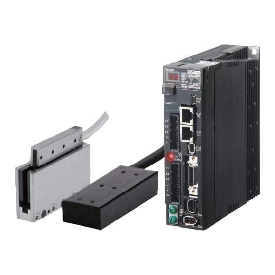
Omron R88L-EC Series User Manual (629 pages)
EtherCAT COMMUNICATIONS Linear Motor Type
Brand:
Omron
| Category:
Servo Drives
| Size: 8.41 MB
Table of Contents
Introduction
3
Manual Configuration
4
Manual Structure
5
Sections in this Manual
7
Table of Contents
8
Contents
9
Terms and Conditions Agreement
14
Safety Precautions
16
Regulations and Standards
28
Items to Check after Unpacking
31
Revision History
34
Features and System Configuration
35
Outline
36
Features of G5-Series Servo Drives
36
What Is Ethercat
37
Object Dictionary
37
System Configuration
38
Names and Functions
40
Servo Drive Part Names
40
Servo Drive Functions
41
System Block Diagram
42
Unit Versions
46
Confirmation Method
46
Models and External Dimensions
47
Servo System Configuration
48
How to Read Model Numbers
50
Servo Drive
50
Linear Motor
51
Model Tables
53
Servo Drive Model Table
53
Linear Motor Model Table
53
Servo Drive and Linear Motor Combination Tables
54
Cable and Peripheral Device Model Tables
56
External and Mounting Dimensions
58
Servo Drive Dimensions
58
Linear Motor Dimensions
66
External Regeneration Resistor Dimensions
73
Reactor Dimensions
74
Mounting Bracket Dimensions
77
Specifications
79
Servo Drive Specifications
80
General Specifications
80
Characteristics
81
Ethercat Communications Specifications
83
Ethercat Communications Connector Specifications (RJ45)
83
Control I/O Specifications (CN1)
84
Control Input Circuits
86
Control Input Details
87
Control Output Circuits
89
Control Output Details
90
External Encoder Specifications
94
External Encoder Connector Specifications (CN4)
95
Analog Monitor Connector Specifications (CN5)
99
USB Connector Specifications (CN7)
100
Safety Connector Specifications (CN8)
100
Overload Characteristics (Electronic Thermal Function)
103
Linear Motor Specifications
106
General Specifications of Iron-Core Linear Motors
106
Performance Specifications of Iron-Core Linear Motors
107
Iron-Core Linear Motor Speed - Force Characteristics
110
Temperature Sensor Specifications of Iron-Core Linear Motors
113
General Specifications of Ironless Linear Motors
114
Performance Specifications of Ironless Linear Motors
114
Ironless Linear Motor Speed - Force Characteristics
117
Temperature Sensor Specifications of Ironless Linear Motors
122
Cable Specifications
123
Cable and Connector Specifications
124
Resistance to Bending of Robot Cable
124
External Encoder Cable Specifications
125
Connector Specifications
126
Ethercat Communications Cable Specifications
127
Analog Monitor Cable Specifications
130
Control Cable Specifications
131
External Regeneration Resistor Specifications
136
Reactor Specifications
137
System Design
139
Installation Conditions
140
Iron-Core Linear Motor Installation Conditions
142
Ironless Linear Motor Installation Conditions
148
Wiring
152
Peripheral Equipment Connection Examples
152
Main Circuit and Linear Motor Connections
156
Terminal Block Wire Sizes
160
Terminal Block Wiring Procedure
162
Wiring Conforming to EMC Directives
164
100-VAC and 200-VAC Input Servo Drive Models
164
400-VAC Input Servo Drive Models
165
Conformity to IEC 61800-5-1
167
Noise Reduction
169
Wiring Method
169
Selecting Connection Components
173
Regenerative Energy Absorption
187
Calculating the Regenerative Energy
187
Servo Drive Regeneration Absorption Capacity
189
Regenerative Energy Absorption with an External Regeneration Resistor
190
Connecting an External Regeneration Resistor
191
Ethercat Communications
195
Display Area and Settings
196
Node Address Setting
196
Status Indicators
197
Structure of the CAN Application Protocol over Ethercat
198
Ethercat State Machine
199
Process Data Objects (Pdos)
200
PDO Mapping Settings
200
Sync Manager PDO Assignment Settings
201
Fixed PDO Mapping
201
Variable PDO Mapping
203
Multiple PDO Mapping
204
Service Data Objects (Sdos)
206
Synchronization with Distributed Clocks
207
Emergency Messages
208
Sysmac Device Features
209
Basic Control Functions
213
Cyclic Synchronous Position Mode
214
Related Objects
215
Block Diagram for Position Control Mode
216
Cyclic Synchronous Velocity Mode
217
Related Objects
218
Objects Requiring Settings
218
Related Functions
218
Block Diagram for Speed Control Mode
219
Cyclic Synchronous Torque Mode
220
Related Functions
222
Block Diagram for Force Control Mode
222
Profile Position Mode
223
Related Objects
224
Description of Function
225
Controlword (6040 Hex) in Profile Position Mode
226
Statusword (6041 Hex) in Profile Position Mode
226
Homing Mode
227
Connecting with OMRON Controllers
228
Applied Functions
231
Output Signals
235
Positive and Negative Drive Prohibition Functions
238
Overrun Protection
241
Operating Conditions
241
Objects Requiring Settings
241
Operation Example
242
Backlash Compensation
243
Brake Interlock
245
Objects Requiring Settings
245
Operation Timing
246
Electronic Gear Function
250
Objects Requiring Settings
250
Operation Example
251
Force Limit Switching
252
Operating Conditions
252
Objects Requiring Settings
252
Soft Start
254
Objects Requiring Settings
254
Soft Start Acceleration or Deceleration Time
254
S-Curve Acceleration or Deceleration Time
255
Gain Switching Function
256
Objects Requiring Settings
256
Gain Switching Based on the Control Mode
258
Diagrams of Gain Switching Setting
261
Position Gain Switching Time (3119 Hex)
266
Safety Function
273
Safe Torque off Function
274
Safety Input Signals
275
External Device Monitor (EDM) Output Signal
276
Relationship between Safety Input Signals and EDM Output Signal
276
Operation Example
277
Connection Example
279
Servo Parameter Objects
281
Basic Settings
282
Gain Settings
287
Vibration Suppression Settings
298
Analog Control Objects
305
Interface Monitor Settings
310
Extended Objects
321
Special Objects
327
Linear Motor Objects
341
Operation
352
Operational Procedure
352
Preparing for Operation
354
Items to Check before Turning on the Power Supply
354
Turning on the Power Supply
356
Checking the Displays
356
Preparing the Linear Motor for Operation
358
Linear Motor Setup
363
Outline of Linear Motor Setup
364
Operation from the CX-Drive
364
Connection from the CX-Drive Via Network
373
Connection from the Sysmac Studio Via Network
375
Trial Operation
377
Preparations for Trial Operation
377
Trial Operation Via USB Communications from the CX-Drive
378
Setup Via Network
378
Adjustment Functions
379
Gain Adjustment
383
Purpose of the Gain Adjustment
383
Gain Adjustment Methods
383
Gain Adjustment Procedure
384
Realtime Autotuning
385
Operating Conditions
386
Objects Requiring Settings
386
Setting Realtime Autotuning
387
Setting Machine Rigidity
388
Objects to be Updated
390
Manual Tuning
393
Preparation for Manual Tuning
393
Position Control Mode Adjustment
394
Damping Control
395
Operating Conditions
395
Objects Requiring Settings
396
Operating Procedure
397
Adaptive Filter
399
Operating Conditions
400
Objects Requiring Settings
400
Objects to be Set Automatically
401
Operating Procedure
401
Notch Filters
402
Objects Requiring Settings
403
Notch Filter Width and Depth
404
Disturbance Observer Function
406
Operating Conditions
406
Objects Requiring Settings
407
Operating Procedure
407
Friction Force Compensation Function
408
Operating Conditions
408
Objects Requiring Settings
408
Operating Procedure
409
11-10Feed-Forward Function
410
Objects Requiring Settings
410
Operating Procedure
411
11-11Instantaneous Speed Observer Function
413
Operating Conditions
413
Objects Requiring Settings
414
Operating Procedure
414
Actions for Problems
416
Preliminary Checks When a Problem Occurs
416
Precautions When a Problem Occurs
417
Replacing the Linear Motor or Servo Drive
417
Warnings
419
Related Objects
419
Warning List
420
Errors
423
Error List
423
Immediate Stop Operation at Errors
425
Troubleshooting
427
Troubleshooting with Error Displays
427
Troubleshooting with the al Status Code
441
Troubleshooting Using the Operation State
442
Periodic Maintenance
449
Linear Slider Life Expectancy
449
Servo Drive Life Expectancy
450
Appendices
451
Cia402 Drive Profile
452
Controlling the State Machine of the Servo Drive
452
A-1-2 Modes of Operation
454
A-1-3 Communications Cycles and Corresponding Modes of Operation
455
A-1-4 Modes of Operation and Applied Functions
456
A-1-5 Changing the Mode of Operation
457
A-1-6 Homing Mode Specifications
465
Communication Objects
475
PDO Mapping Objects
481
Sync Manager Communication Objects
494
A-1-11 Manufacturer Specific Objects
499
A-1-12 Servo Drive Profile Objects
505
Object List
527
Sysmac Error Status Codes
545
A-3-1 Error Table
545
A-3-2 Error Description
559
Response Time in Ethercat Process Data Communications
617
A-4-1 Input Response Time
617
A-4-2 Output Response Time
618
Ethercat Terminology
619
Advertisement
Advertisement
Related Products
Omron R88L-EA-AF
OMRON R88D-GN Series
Omron R88M-U05030WA-S1
Omron R88M-U10030VA-BS1
Omron R88M-U20030VA-S1
Omron R88M-U30030WA-S1
Omron R88D-UP04H(A)
Omron R88D-UP12L(A)
Omron R88D-KNA5L-ECT-R
Omron R88D-KN30H-ECT-R
Omron Categories
Blood Pressure Monitor
Controller
Accessories
Switch
Inverter
More Omron Manuals
Login
Sign In
OR
Sign in with Facebook
Sign in with Google
Upload manual
Upload from disk
Upload from URL