Sign In
Upload
Manuals
Brands
OMRON Manuals
Control Unit
CS1W-MC221 - 02-2008
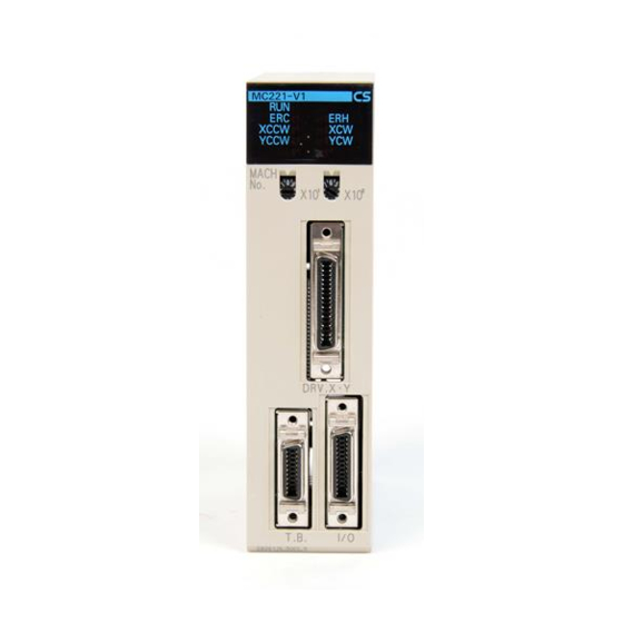
OMRON CS1W-MC221 - 02-2008 Manuals
Manuals and User Guides for OMRON CS1W-MC221 - 02-2008. We have
1
OMRON CS1W-MC221 - 02-2008 manual available for free PDF download: Operation Manual
OMRON CS1W-MC221 - 02-2008 Operation Manual (705 pages)
Motion Control Units
Brand:
OMRON
| Category:
Control Unit
| Size: 12.51 MB
Table of Contents
Table of Contents
8
Precautions
20
General Precautions
21
Intended Audience
21
Safety Precautions
21
Operating Environment Precautions
22
Application Precautions
23
Conformance to EC Directives
25
Applicable Directives
25
Concepts
25
Conformance to EC Directives
26
Section 1 Features and System Configuration
28
Features and System Configuration
28
Features
29
Overview
29
Description of Features
30
System Configuration
31
System Configuration Example (CS1W-MC421)
31
Basic Operations
34
Motion Control
35
Other Functions
37
Summary of Function
38
Control System Configuration and Principles
39
Servo System
39
Feedback Pulses
42
CW and CCW
42
Specifications
43
Overview of Operations
48
Performance Chart
50
CX-Motion Functions
51
Teaching Box Functions
52
Data Exchange
53
Overall Structure
53
Explanation
54
Internal Block Diagram
55
Data Transfer Overview
56
Overview of G-Language Programs in the MC Unit
57
Programs and Tasks
57
Manual and Automatic Operation
59
G Language
60
G-Language Codes
62
Commands Listed According to Purpose
64
Comparison with Earlier MC Unit Model
65
Changing from the C200H-MC221 to the CS1W-MC421/MC221
67
Basic Operating Procedure
69
Methods for Using MC Unit Functions
70
Overview of Version 1 Upgrades
72
Using Customized Functions
75
Easy Backup Function
124
Section 2 Installation
128
Installation
128
Nomenclature and Unit Settings
129
Nomenclature
129
Installation
131
System Configuration Precautions
131
Mounting to the Backplane
131
Unit Handling Precautions
132
Dimensions
133
Wiring
134
I/O Connector
134
DRV Connectors
139
Driver Cables (Optional)
143
Wiring Connectors
145
Connection Examples for Special Servo Driver Cable
146
MPG Wiring
152
Interface Circuits
153
Wiring Precautions
155
Motor Runaway
157
Wiring Check Function
159
Failsafe Circuits
160
Failsafe Principles
161
Failures in the Command System
161
Failures in the Feedback System
165
Other Safety Features
165
Wiring Check Troubleshooting
166
Wiring Errors
166
Wiring Check Principles
166
Wiring Error Cause and Countermeasures
167
Checking for Wiring Errors
168
Changing the Mechanical Direction of Operation
168
Connecting Peripheral Devices
169
Connecting a Personal Computer to the CPU Unit
170
Connecting the Teaching Box
171
Section 3 MC Unit Internal Data Configuration
174
MC Unit Internal Data Configuration
174
Data Configuration
175
Determining the Task Configuration
176
Task Configuration
176
System Parameters
178
Description of System Parameters
179
System Parameter Addresses
182
Data Configuration for System Parameters
183
Timing that Validates Transferred System Parameters
197
System Parameters
198
Position Data
214
Position Data Addresses
215
Position Data Configuration
215
Monitor Data
216
Monitor Data Addresses
216
Monitor Data Configuration
218
Command Area
223
Command Area Addresses
224
Command Area Data Configuration
224
Section 4 Data Transfer and Storage
228
Data Transfer and Storage: Overview
229
Data Transfer
229
Types of Data
230
Using IOWR and IORD Instructions to Transfer Data
231
Transferring Position Data Using the Command Area
233
Data Storage
235
IOWR and IORD Specifications
236
Iowr: Intelligent I/O Write
236
Iord: Intelligent I/O Read
240
Transferring Data Using the Command Area
244
Saving Data
248
Execution
248
Command Specifications
248
Ladder Program Example
249
Section 5 Exchanging Data with the CPU Unit
250
Exchanging Data with the CPU Unit
250
Overall Structure
251
PLC Interface Area
253
Data Transfer Words
253
Flash Memory
254
Restart Flags
254
MC Unit Initialization
254
Controlling the MC Unit from the CPU Unit
255
Manual and Automatic Modes
255
Manual Mode
257
Automatic Mode
259
PLC Interface Area
264
PLC Interface Area Lists
264
Interface Specifics
287
System Controls
288
Controls Common to All Tasks
292
Task Control Bits
293
Axis Control Bits
306
System Status
328
Task Status
336
Axis Status Flags
345
Section 6 Basic Positioning Operations
352
Basic Positioning Operations
352
Overview
353
Summary of Operations
353
PTP Control
354
Linear Interpolation
355
Circular Interpolation
358
Helical Circular Interpolation
359
Interrupt Feeding
361
Traverse Function
363
Operating Modes
364
Stop Mode
365
Pass Mode
366
In-Position Check off Mode
369
Changing Parameters
372
Stopover Function
373
CPU Unit Interrupt Processing
375
Override Function
376
Resetting the Error Counter
378
Servo Lock and Unlock
380
Timing Charts
381
Related System Parameters
382
Backlash Correction
383
Setting Backlash Correction
384
Automatic Loading
386
Executing Automatic Loading
387
Related Bits in the PLC Interface Area
389
Present Position Preset
390
Executing Present Position Preset
391
Electronic Gear Function
392
Setting the System Parameters
392
Related Bits
396
Acceleration and Deceleration Curves
396
Unlimited Feeding
397
Setting System Parameters
398
Stopping
399
Changes Made to the Driver Alarm Input Stop Method
400
Section 7 G-Language Programming
402
G-Language Programming
402
Programs and Tasks
403
Overview
403
G Language Overview
404
List of G-Language Commands
404
G-Language Formats
405
List of G Symbols
407
Declaring Program Numbers and Axes
409
Default Mode and Coordinate System
410
G-Language Commands
411
G00: Positioning
411
G01: Linear Interpolation
412
G02 and G03: CIRCULAR INTERPOLATION
415
G04: Dwell Timer
422
G10: Pass Mode
423
G11: Stop Mode
425
G13: In-Position Check off Mode
426
G17 to G22: CIRCULAR PLANE SPECIFICATION
427
G26: Reference Origin Return
429
G27: Workpiece Origin Return
430
G28: Origin Search
431
G29: Origin Undefined
432
G30: Speed Control Axis Feeding
432
G31: Interrupt Feeding
433
G32: Traverse
439
G50: Select Reference Coordinate System
443
G51: Select Workpiece Coordinate System
444
G53: Change Workpiece Origin Offset
445
G54: Change Reference Coordinate System Pv
446
G60: Arithmetic Operations
447
G63: Substitution
448
G69: Change Parameter
448
G70: Unconditional Jump
450
G71: Conditional Jump
451
G72: Subroutine Jump
451
G73: Subroutine End
452
G74: Optional End
452
G75: Optional Skip
454
G76: Optional Program Pause
455
G79: Program End
456
G90: Absolute Specification
457
G91: Incremental Specification
457
M Code Outputs
458
Introduction
458
M Code Data
460
M Code Examples
460
Effect of Mode Changes on M Code Resets
460
Clearing M000 to M499 with Forced Block End or G74
460
Clearing M500 to M999 with Forced Block End or G74
462
M Code Outputs in Pass Mode
463
Stopover Function and Resetting M Codes
464
D Code Outputs
465
Stopover Function
467
Precautions on the Stopover Function
470
G-Language Programming Examples
472
Programming Examples
473
Executing MC Programs from the Ladder Program
489
Establishing the Origin
492
Overview
493
Input Signals Required for an Origin Search
495
Origin Search Methods and Parameters
495
Origin Search Operations
497
Absolute Encoders
506
Setting the Origin with an Absolute Encoder
507
Absolute Encoder Interface Specifications
510
Teaching
514
Introduction
515
Setting the Teaching Address
515
Performing Teaching
517
Errors During Teaching
519
Getting Started
522
Operation Details
523
System Configuration and Wiring
525
Considerations When Starting up the MC Unit
545
Troubleshooting
548
Troubleshooting Tables
549
Error Indicators
558
System Error Codes
559
Task Error Codes
563
Axis Error Codes
568
Error Log
573
Maintenance and Inspection
576
Routine Inspections
577
A Performance
580
B G-Language Codes
590
C PLC Interface Area Lists
592
D System Parameters
616
E Control Bit/Flag Timing Charts
640
F Origin Search Patterns
656
G Encoder Divider Rate and Rotation Speed for OMRON Servo Drivers
685
H MC Program Coding Sheet
686
I System Parameter Settings
688
J Position Data Coding Sheet
694
Index
696
Revision History
704
Advertisement
Advertisement
Related Products
OMRON CS1W-MC221 -
Omron CS1W-MC221-V1
OMRON CS1W-MC421 - DATASHEET 2
OMRON CS1W-MCH71 -
Omron CS1W-MC421-V1
OMRON CS1W-NC113 - REV 02-2008
Omron CS1W-CLK12-V1
Omron CS1W-LCB01
Omron CS1W-LC001
Omron SYSMAC CS1W-NC433
OMRON Categories
Blood Pressure Monitor
Controller
Accessories
Switch
Inverter
More OMRON Manuals
Login
Sign In
OR
Sign in with Facebook
Sign in with Google
Upload manual
Upload from disk
Upload from URL