Sign In
Upload
Manuals
Brands
NTI Manuals
Measuring Instruments
ENVIROMUX-2DB
NTI ENVIROMUX-2DB Manuals
Manuals and User Guides for NTI ENVIROMUX-2DB. We have
1
NTI ENVIROMUX-2DB manual available for free PDF download: Installation And Operation Manual
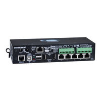
NTI ENVIROMUX-2DB Installation And Operation Manual (135 pages)
ENVIROMUX Series Enterprise Environment Monitoring System
Brand:
NTI
| Category:
Measuring Instruments
| Size: 7.88 MB
Table of Contents
Table of Contents
3
Introduction
9
Materials
11
Supported Web Browsers
12
Features and Functions
13
Installation
15
Mounting Instructions-16D
15
Figure 1- Secure Rack Mount Ears to ENVIROMUX-16D
15
Figure 2- Mount ENVIROMUX in a Rack
15
Mounting Instructions-5D / -2D
16
Figure 3- Rotate the Tabs for Zero-RU Mounting
16
Sensor Attachment
17
RJ45 Sensor Ports
17
Figure 4- Sensors Connected by Cables with RJ45 Connectors
17
Figure 5- Contact Sensor Wired to RJ45 Socket
17
Digital in Terminals
18
Liquid Detection Sensors
18
Figure 6- DIGITAL in Terminal Connections
18
Figure 7- Secure Liquid Detection Sensor with Tape
19
Figure 8- Portion of Water Sensor Configuration Page
19
Alarm(Beacon/Siren) Connections
20
Figure 9- Connect Visual and Audible External Indicators
20
Connect Output Devices
21
Figure 10- Install Additional Devices to Output Terminals
21
Terminal Connection for RS232
22
Figure 11- Connect a Terminal for Direct RS232 Serial Communication
22
Figure 12- Connect a Terminal Using USB Console Port
22
Ethernet Connection for Remote User Control
23
Figure 13- Connect ENVIROMUX to the Ethernet
23
Figure 14- Connect ENVIROMUX to Ethernet Via SFP
23
Modem Connection
24
USB GSM Modem
24
Figure 15- Install USB GSM Modem
24
Serial GSM Modem
26
Power Connection-ENVIROMUX-16D
27
Dual Power Option
27
Figure 16- Connect the Power Cord
27
Figure 17- Power Connections for ENVIROMUX with Dual Power Option
27
DC Power Option
28
Power Connection- ENVIROMUX-5D/-2D
28
Figure 18- 48VDC Power Option Connections
28
Figure 19- Connect the AC Adapter and Power-Up
28
Figure 20- Power Connections on ENVIROMUX-5D-48VDP
29
Figure 21- Power Supply Sensors-Summary Page
29
Figure 22- Connect Serially Controlled Device
30
Figure 23- Create User "Rs232
30
Remote RS232 Device Control
30
Figure 24- Connection to Serial Device Successful
31
Overview - Use and Operation
32
Sensors
32
IP Assignment
32
User Management
32
Alerts
32
Data and Event Logging
33
Email
33
Syslog
33
Snmp
33
Modbus TCP/IP Support
33
External Modem
33
Power-On/Reset Operation
33
Out-Of-Box Operation
33
Expandability
33
Figure 25- Device Discovery Tool Page
34
Device Discovery Tool
34
Use and Operation Via Web Interface
35
Log in and Enter Password
35
Figure 26- Login Prompt to Access Web Interface
35
Figure 27- Summary Page
35
Monitoring
36
Summary Page
36
Figure 28- Summary Page
36
Power Supplies
37
Power Supply Alert Configuration
37
Figure 29- Power Supply Status- Dual Power Model
37
Figure 30- Power Supply Alerts Configuration-Part 1
37
Figure 31- Power Supply Alerts Configuration-Part 2
38
Internal Sensors
39
External Sensors
39
Figure 32- External Sensor Reading
40
Figure 33- Sensor Configuration Page (1)
41
Figure 34- Sensor Configuration Page (2)
42
Figure 35- Sensor Configuration Page (3)
43
External Sensor Configuration
44
Figure 36- Sensor Configuration Page (4)
44
Figure 37- Chart to Setup Alert Notification
46
Specialized Sensors (for S420MA-24V Current Sensor Configuration Only)
48
Figure 38- Current Sensor Added to ENVIROMUX
48
Figure 39- Configuration of Sensor Connected to ENVIROMUX-S420MA-24V
48
Contact Sensors
50
Figure 40- List of Sensors
50
Figure 41- Add a Contact Sensor
50
Figure 42- Contact Sensor Configuration Page
51
Figure 43- Digital Input Sensors
52
Figure 44- Select Connector on ENVIROMUX
52
Figure 45- Configure New Sensor
53
Figure 46- Status of Digital Input #2
53
Figure 47- Open Configuration from Digital Input Page
53
Figure 48- Connection that Supports Tachometer Sensor
54
Monitor Output Relay
55
Figure 49- Monitoring Output Relays
55
Figure 50- Output Relay Status
55
Figure 51- Output Relay Contact State
55
Figure 52- Configure Output Relay
56
IP Devices
57
Figure 53- IP Devices Monitored
57
Figure 54- Add New IP Device
57
Figure 55- IP Device Configuration
58
Figure 56- IP Device Configuration-More
59
IP Cameras
61
Figure 57- Monitoring IP Cameras
61
Figure 58- IP Camera Configuration
61
Administration
62
System Configuration
62
Figure 59- System Configuration Page
62
Figure 60- Configuration Backup and Restore
63
Figure 61- Select What will be Displayed on Connected USB LCD Monitor
64
Figure 62- Configure the Purpose of the "RS232 AUX" Port
64
Figure 63- System Configuration-Continued
65
Administration-Enterprise Setup
66
Figure 64- Enterprise Configuration Page
66
Figure 65- GSM Modem Status
67
Figure 66- SMS Relay Configuration
67
Administration-Network Setup
68
Figure 67- Network Configuration Page
68
Figure 68- Apply Ipv4 or Ipv6 Settings
68
Figure 69- Configure SMTP, SNMP, and Security Settings
69
Figure 70- Configure 3G Data Connection
70
Figure 71- Setup SNMP to Control Output Relays
72
User Configuration
73
Figure 72- Usernames List and Status
73
Figure 73- Edit User Profile for Root User
73
Figure 74- more User Settings
74
Figure 75-Summary Page for User Without Admin Privileges
76
Group Names
77
Figure 76- Enter Custom Group Names
77
Security
78
Figure 77- Security Configuration Page
78
Figure 78- Security Configuration- IP Filtering Rules
80
System Information
81
Figure 79- System Information Page
81
Administration- Firmware
82
Figure 80- Update Firmware Page
82
Advanced-Cascade Configuration
83
Figure 81- Cascade Configuration Options
83
Figure 82- Master with Local (RS485) Slaves
84
Figure 83- Cascade Configuration with Ethernet Slaves
84
Figure 84- Configure Which Slaves will be Connected to the Master
85
Figure 85- Apply Alert Settings to Alert for Slave Connection Loss
85
Figure 86- Portion of Summary Page from a Master with a Slave
87
Reboot the System
88
Figure 87- Reboot System Page
88
Figure 88- System Is Rebooting
88
Smart Alerts
89
Figure 89- Events Used for Smart Alerts
89
Figure 90- Sensor to be Used for a Predefined Event
89
Figure 91- Configuration Options for New Event
90
Figure 92- Event Configuration Options Continued
92
Figure 93- Smart Alert Summary Page
93
Figure 94- Smart Alert Configuration
93
Figure 95- Smart Alert Configuration- Continued
94
Figure 96- Smart Alert Configuration- Continued
94
Figure 97- Event Logical Function Diagram
97
Figure 98- Examples of Smart Alert Conditions
98
Log
99
View Event Log
99
Figure 99- Event Log Page
99
View Data Log
100
Figure 100- Data Log Page
100
Log Settings
101
Figure 101- Log Settings Page
101
Support
102
Logout
102
Figure 102- Support
102
Front Panel Controls and LED Indicators
103
System Reset Button
103
Alarm Test/Silence Button
104
Restore Defaults Button
104
Battery Backup
104
Enviromux-16D
104
Enviromux-5Db / -2Db
104
USB Port
105
Serial Control
105
Modbus TCP/IP Support
106
Modbus TCP Function Codes Definition
106
Function Code 01 - Read the State of Output Relays
106
Function Code 02 - Read the State of Digital Inputs
107
Function Code 04 - Read Internal/External Sensors Floating Point Values
108
Write Data to Force Multiple Output Relays Active/Inactive
110
How to Setup Email
111
How to Setup SNMP
113
How to Setup Syslog
116
Locating Oids
119
ENVIROMUX-16D Specifications
123
Front Panel Interface
123
RJ45 Sensor Inputs
123
Digital Inputs
123
Output Relays
123
Beacon Port & Siren Port
123
USB Device Ports
123
Control Serial Port "RS232
124
USB-Serial Port "Console
124
Auxiliary Power Port
124
Ethernet Port
124
Back-Up Battery
124
General Specifications
124
Tcp/Ip
124
ENVIROMUX-5D Specifications
125
User Interface
125
RJ45 Sensor Inputs
125
Digital Inputs
125
Output Relays
125
Alarm Port
125
USB Device Ports
125
USB-Serial Port "Console
125
Auxiliary Power Port
126
Ethernet Port
126
General Specifications
126
Tcp/Ip
126
Optional Battery
126
ENVIROMUX-2D Specifications
127
User Interface
127
RJ45 Sensor Inputs
127
Digital Inputs
127
Output Relays
127
USB Device Ports
127
USB-Serial Port "Console
127
Auxiliary Power Port
127
Ethernet Port
128
General Specifications
128
Tcp/Ip
128
Optional Battery
128
Wiring Methods
129
RS485 Sensor Cable
129
Contact Sensor Wiring
129
Troubleshooting
130
Recycling Information
132
Index
133
Warranty Information
135
Advertisement
Advertisement
Related Products
NTI ENVIROMUX-5D
NTI ENVIROMUX-16D
NTI ENVIROMUX-2D
NTI ENVIROMUX-MINI-LXO
NTI ENVIROMUX-5DB
NTI ENVIROMUX E-5D
NTI ENVIROMUX E-2D
NTI E-STSM-E7
NTI E-STHS-LCDW
NTI E-STHSB
NTI Categories
Extender
Boiler
Switch
Media Converter
Cables and connectors
More NTI Manuals
Login
Sign In
OR
Sign in with Facebook
Sign in with Google
Upload manual
Upload from disk
Upload from URL