Sign In
Upload
Manuals
Brands
National Instruments Manuals
I/O Systems
SC-2062
National Instruments SC-2062 Manuals
Manuals and User Guides for National Instruments SC-2062. We have
2
National Instruments SC-2062 manuals available for free PDF download: User Manual
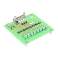
National Instruments SC-2062 User Manual (92 pages)
General-Purpose Termination Breadboards
Brand:
National Instruments
| Category:
Computer Hardware
| Size: 2 MB
Table of Contents
Table of Contents
6
About this Manual
11
Organization of this Manual
11
Conventions Used in this Manual
12
Related Documentation
12
Customer Communication
13
Chapter 1 Introduction
14
About the SC-207X Series Boards
14
Table 1-1. DAQ Devices for Use with SC-207X Series Boards
15
What You Need to Get Started
17
Optional Equipment
17
Software
17
Unpacking
18
Chapter 2 SC-2070 Board
19
Analog Input
20
Figure 2-1. SC-2070 Board Parts Locator Diagram
20
Temperature Sensor
21
Figure 2-2 Onboard Equivalent Circuit
21
Table 2-1. Component Positions in each Channel
21
Shield Ground
22
Fuse and Power LED
22
Digital and Timing Signals
22
Figure 2-3. W1 Jumper Settings
22
Figure 2-4. W2 Jumper Settings
22
Board-To-Board Cabling
23
Figure 2-5. Direct Connection between an MIO-16 Board and the SC-2070 Board
23
Figure 2-6. Connection between an MIO-16 Board and the SC-2070 Board Via the SC-2050 Board
23
Table 2-2. DAQ Boards Used with the SC-2070 Board
23
Mounting
24
Applications
24
Soldering and Desoldering on the SC-2070 Board
24
Channel Configurations
25
Connecting Nonreferenced or Floating Signal Sources
25
Differential Inputs
25
Single-Ended Inputs
26
Connecting Ground-Referenced Signal Sources
27
Differential Inputs
27
Single-Ended Inputs
27
Building Lowpass Filters
28
Figure 2-8. Normalized Frequency Response of Lowpass Filter
28
Building Highpass Filters
30
Figure 2-10. Normalized Frequency Response of Highpass Filter
30
Building Attenuators (Voltage Dividers)
32
Figure 2-12. Attenuator for Use with Differential Inputs
33
Working with Thermocouples
34
Using the SC-2070 Board for Thermocouple Measurements
35
Input Filtering and Broken Thermocouple Detection (Optional)
35
Selecting the Gain and Input Ranges
36
Figure 2-13. Thermocouple Circuit with Open Thermocouple Detect and Lowpass Noise Filter
36
Linearizing the Data
37
Table 2-3. Thermocouple Voltage Output Extremes (MV)
37
Table 2-4. NBS Polynomial Coefficients
38
Differential Measurements
39
An Example of Using Thermocouples in Differential Mode
39
Single-Ended Measurements
40
An Example of Using Thermocouples in Single-Ended Mode
40
Sources of Error
41
Thermocouple Measurement Accuracies
41
Additional Signal Connection Information
42
Table 2-5. Thermocouple Measurement Accuracies
42
Chapter 3 SC-2071 Board
43
Analog Input
44
Figure 3-1. SC-2071 Board Parts Locator Diagram
44
Figure 3-2. Onboard Equivalent Circuit
45
Table 3-1. Component Positions in each Channel
45
Temperature Sensor
46
Shield Ground
46
Fuse and Power LED
46
Figure 3-3. W1 Jumper Settings
46
Figure 3-4. W2 Jumper Settings
46
Digital and Timing Signals
47
Board-To-Board Cabling
47
Figure 3-5. Direct Connection between a Lab/1200 Device and the SC-2071 Board
47
Table 3-2. DAQ Devices Used with the SC-2071 Board
47
Figure 3-6. Daisy-Chaining a Lab/1200 Device to a BNC-2081
48
Figure 3-7. Connection between a Lab/1200 Device and the SC-2071 Board Via the SC-2053 Board
48
Mounting
49
Applications
49
Soldering and Desoldering on the SC-2071 Board
49
Connecting Floating Signal Sources
50
Connecting Grounded Signal Sources
50
Building Lowpass Filters
50
Figure 3-8. Normalized Frequency Response of Lowpass Filter
51
Building Highpass Filters
52
Figure 3-10. Normalized Frequency Response of Highpass Filter
53
Building Attenuators (Voltage Dividers)
54
Figure 3-12. Attenuator for Use with SC-2071 Board Inputs
55
Working with Thermocouples
56
Using the SC-2071 Board for Thermocouple Measurements
57
Input Filtering and Broken Thermocouple Detection (Optional)
57
Selecting the Gain and Input Ranges
58
Figure 3-13. Thermocouple Circuit with Open Thermocouple Detect and Lowpass Noise Filter
58
Linearizing the Data
59
Table 3-3. Thermocouple Voltage Output Extremes (MV)
59
Measurement Connections
60
Table 3-4. NBS Polynomial Coefficients
60
An Example of Using Thermocouples
61
Sources of Error
61
Thermocouple Measurement Accuracies
62
Additional Signal Connection Information
63
Table 3-5. Thermocouple Measurement Accuracies
63
Chapter 4 SC-2072 Board
64
Figure 4-1. SC-2072 Board Parts Locator Diagram
65
Signal Connections
66
Figure 4-2. SC-2072D Board Parts Locator Diagram
66
Power Connections
67
Table 4-1. Switch S2 Settings for National Instruments DAQ Devices
67
Fuses and Power LED
68
Board-To-Board Cabling
69
Figure 4-3. Direct Connection between a TIO-10 Board and the SC-2072 Board
69
Figure 4-4. Connection between a DIO-24 Board and the SC-2072 Board Via the SC-2051 Board
69
Mounting
70
Soldering and Desoldering on the SC-2072 Board
70
Installation and Connections
71
Hardware Installation
71
Hardware Installation for the SC-2070 and the SC-2071
71
Hardware Installation for the SC-2072
72
Installing the SC-205X Series Cable Adapter Boards
72
Installing the BNC-2081 Analog Breakout Board
73
Rack Mounting
73
Figure 5-1. Mounting Locations for SC-207X Series Boards
73
Figure 5-2. Attaching a Mountable Board to the Chassis
73
Figure 5-3. Double-Height Mounting
74
External Power Connection (if Necessary)
75
Table 5-1. Amount of Power Supplied by DAQ Devices
76
SC-207X Series Board Connection
77
Figure 5-4. Connections between DAQ Devices and SC-205X Series Boards and between SC-205X Series Boards and SC-2070 and SC-2071 Boards
77
Signal Connections
78
Ribbon Cable Connectors
78
Screw Terminal Connections for the SC-2070 and the SC-2071
78
Table 5-2. SC-205X Series Board Connectors Compatible with the SC-207X Series Boards
78
Screw Terminal Connections for the SC-2072
79
Rack-Mount Chassis Cover Attachment
79
Appendix A Specifications
80
Customer Communication
82
Glossary
85
Index
86
Advertisement
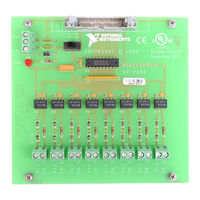
National Instruments SC-2062 User Manual (77 pages)
Brand:
National Instruments
| Category:
I/O Systems
| Size: 1 MB
Table of Contents
Table of Contents
5
About this Manual
8
Organization of this Manual
8
Conventions Used in this Manual
9
Related Documentation
9
Customer Communication
10
Introduction
11
Table 1-1. Data Acquisition Boards for Use with SC-206X Series Boards
11
Figure 1-1. SC-2060 Board Connected to Host Data Acquisition Board Via an SC-2050 Board
12
Figure 1-2. SC-2060 Boards and SC-2050 Board Mounted in 19 In. Rack Mount with Connection to Host Data Acquisition Board
12
Software
13
What Your Kit Should Contain
13
Optional Equipment
14
Unpacking
14
Chapter 2 SC-2060 Board
15
Figure 2-2. SC-2060 Power Circuit
16
Figure 2-3. Onboard Equivalent Circuit
16
Specifications
17
Optically Isolated Digital Input
17
Power Requirement (from Host Board or External Power Supply)
18
Physical
18
Operating Environment
18
Storage Environment
18
Mounting and Connection to Data Acquisition Boards
18
Table 2-1. Data Acquisition Boards for Use with the SC-2060 Board
19
SC-2061 Board
20
Figure 3-1. SC-2061 Board Parts Locator Diagram
20
Specifications
22
Optically Isolated Digital Output
22
Power Requirement (from Host Board or External Power Supply)
22
Physical
23
Operating Environment
23
Storage Environment
23
Mounting and Connection to Data Acquisition Boards
23
Table 3-1. Data Acquisition Boards for Use with the SC-2061 Board
23
Chapter 4 SC-2062 Board
24
Figure 4-1. SC-2062 Board Parts Locator Diagram
24
Figure 4-2. SC-2062 5 V Onboard Equivalent Circuit
25
Specifications
26
Electromechanical Relay Digital Output
26
Power Requirement (from Host Board or External Power Supply)
27
Physical
27
Operating Environment
27
Storage Environment
27
Mounting and Connection to Data Acquisition Boards
27
Table 4-1. Data Acquisition Boards for Use with the SC-2062 Board
28
Installation and Operation
29
Hardware Installation
29
Figure 5-1. Mounting Locations for SC-205X and SC-206X Series Boards
30
Figure 5-2. Attaching a Mountable Board to the Chassis
30
Figure 5-3. Double-Height Mounting
31
Internal or External Power Selection
32
Table 5-1. Amount of Power Data Acquisition Boards Supply
32
SC-206X Series Board Connection
33
Figure 5-4. Location of the External Power Screw Terminals
33
Figure 5-6. Connecting SC-206X Series Boards to Data Acquisition Boards Via the SC-205X Series Cable Adapter Boards
34
Figure 5-7. Pinout for I/O Connector J1
35
Operation
36
Table 5-2. SC-205X Series Connectors Compatible with SC-206X Series
36
Safety Information
37
HCPL-2611-060 Technical Data
39
Motorola Array Technical Data
60
American Zettler Relay Technical Data
66
Customer Communication
69
Glossary
73
Index
74
Advertisement
Related Products
National Instruments SC-2060
National Instruments SC-2061
National Instruments SC-2071
National Instruments Isolated Analog Input Modules SCC-AI02
National Instruments Isolated Analog Input Modules SCC-AI05
National Instruments Isolated Analog Input Modules SCC-AI13
National Instruments Isolated Analog Input Modules SCC-AI14
National Instruments SCXI-1162HV
National Instruments SCC-CI20
National Instruments SC Express Series
National Instruments Categories
Control Unit
I/O Systems
Controller
Computer Hardware
Measuring Instruments
More National Instruments Manuals
Login
Sign In
OR
Sign in with Facebook
Sign in with Google
Upload manual
Upload from disk
Upload from URL