Sign In
Upload
Manuals
Brands
Mitsubishi Electric Manuals
Servo Drives
MELSERVO MR-J3-200BN-RT
Mitsubishi Electric MELSERVO MR-J3-200BN-RT Manuals
Manuals and User Guides for Mitsubishi Electric MELSERVO MR-J3-200BN-RT. We have
1
Mitsubishi Electric MELSERVO MR-J3-200BN-RT manual available for free PDF download: Handbook
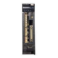
Mitsubishi Electric MELSERVO MR-J3-200BN-RT Handbook (590 pages)
Brand:
Mitsubishi Electric
| Category:
Servo Drives
| Size: 13.98 MB
Table of Contents
Table of Contents
10
Summary of Mr-J3/Mr-J3W Replacement
18
Major Replacement Target Model
19
Servo Amplifier Replacement Target Model
19
Servo Motor Replacement Target Model
19
Flow of Replacement
20
Summary
20
Flow of Review on Replacement
20
Configuration Diagram
21
Changes from MR-J3 Series to MR-J4 Series
22
Changes from MR-J3W Series to MR-J4 Series
24
Review on Replacement
26
Checking the System Prior to Replacement
26
Determination of Base Replacement Model
26
Attachment Compatibility Check
32
Detailed Review on Replacement Model
32
Peripheral Equipment Check
32
Startup Procedure Check
32
Related Materials
32
Catalog
32
Instruction Manual
32
Replacement Tool for Replacing MR-J3 with MR-J4
33
MITSUBISHI ELECTRIC FA Global Website
33
Summary
33
Case Study on Replacement of Mr-J3-_A
35
Review on Replacement Method
35
Replacement Method
35
Differences between Mr-J3-_A_ and Mr-J4-_A
37
Function Comparison Table
37
Comparison of Standard Connection Diagrams
39
List of Corresponding Connectors and Terminal Blocks
41
Comparison of Peripheral Equipment
46
Comparison of Parameters
47
Setting Requisite Parameters Upon Replacement
47
Parameter Comparison List
49
Comparison of Parameter Details
53
Important Points for Replacement
96
Part 3: Review on Replacement of MR-J3-_B_ with MR-J4-_B_ 3- 1 to
98
Case Study on Replacement of Mr-J3-_B
99
Review on Replacement Method
99
Replacement Method
100
Differences between Mr-J3-_B_ and Mr-J4-_B
103
Function Comparison Table
103
Comparison of Networks
105
Comparison of Standard Connection Diagrams
105
List of Corresponding Connectors and Terminal Blocks
106
Comparison of Peripheral Equipment
109
Comparison of Parameters
109
Setting Requisite Parameters Upon Replacement
110
Parameter Comparison List
111
Comparison of Parameter Details
114
Application of Functions
144
Part 4: Replacement of MR-J3W-_B with MR-J4W2-_B 4- 1 to
146
Case Study on Replacement of Mr-J3W-_B
147
Review on Replacement Method
147
Servo Amplifier Replacement Model
147
Replacement Method
148
Differences between Mr-J3W-_B and Mr-J4W2-_B
151
Function Comparison Table
151
Configuration Including Auxiliary Equipment
153
Comparison of Networks
157
Comparison of Standard Connection Diagrams
157
List of Corresponding Connectors and Terminal Blocks
159
Class
159
DC/24 V DC Class
162
Comparison of Peripheral Equipment
164
Comparison of Parameters
165
Setting Requisite Parameters Upon Replacement
166
Parameter Comparison List
167
Comparison of Parameter Details
171
Application of Functions
194
Part 5: Review on Replacement of MR-J3-DU_ with MR-J4-DU_ 5- 1 to
196
Functions and Configuration
197
Differences between MR-J3-DU_ and MR-J4-DU
197
Combination of Converter Unit, Drive Unit, and Servo Motor
198
Configuration Including Peripheral Equipment
200
Installation
202
Installation Direction and Clearances
202
Magnetic Contactor Control Connector (CNP1)
204
Signals and Wiring
206
Comparison of Standard Connection Diagrams
206
When Magnetic Contactor Drive Output Is Enabled (Factory Setting)
206
When Magnetic Contactor Control Connector (CNP1) Is Made Invalid
211
Power-On Sequence
216
List of Corresponding Connectors and Terminal Blocks
224
Converter Unit
224
Converter Unit Parameter Comparison List
232
Converter Unit Comparison of Parameter Details
233
Drive Unit
236
Drive Unit Comparison of Parameter Details
236
Characteristics
238
Overload Protection Characteristics
238
Power Supply Capacity and Generated Loss
241
Inrush Currents at Power-On of Main Circuit/Control Circuit
243
Options and Peripheral Equipment
244
Comparison Table of Cable Option Combinations
244
MR-J3CDL05M (0.5 M) Protection Coordination Cable
245
Selection Example of Wires
246
MR-J3 Series, Power Supply Wire Size
246
MR-J4 Series, Power Supply Wire Size
248
Selection of Molded-Case Circuit Breakers, Fuses, Magnetic Contactors (Example)
250
MR-J3-DU_ Molded-Case Circuit Breakers, Fuses, Magnetic Contactors (Recommended)
250
MR-J4-DU_ Molded-Case Circuit Breakers, Fuses, Magnetic Contactors (Recommended)
250
BU2-(H) Brake Unit
252
Selection
252
Brake Unit Parameter Setting
253
Connection Example
253
Dimensions
269
Regenerative Option
271
Combination and Regenerative Power
271
External Dynamic Brake
272
MR-J3 Series
272
MR-J4 Series
273
Dimensions
273
MR-J3 Series
273
MR-J4 Series
275
Part 6: Common Reference Material 6- 1 to
278
Specification Differences
279
Detailed Specification/Function Differences
279
Servo Amplifier
281
Main Circuit Terminal Block
281
Comparison of Encoder Signals (CN2)
286
Dynamic Brake: Coasting Distance
287
Forced Stop Deceleration Function Selection
297
Servo Setup Software: Setup Software (SETUP221E) => MR Configurator2
299
Servo Amplifier Initializing Time
300
The Pulse Width of the Encoder Z-Phase Pulse
302
Overload Protection Characteristics
303
Comparison of Networks
310
Comparison of Servo System Network Specifications
310
Servo Amplifier Dimensions/Attachment Differences
312
MR-J3 Series => MR-J4 Series Comparison Table of Servo Amplifier Dimensions/Installation Differences
312
General-Purpose Interface/Sscnet Interface 200 V/100 V Class (22 Kw or Less)
312
General-Purpose Interface/Sscnet Interface 400 V Class (22 Kw or Less)
317
General Purpose Interface/Sscnet Interface 200 V Class (30 Kw or More)
321
General Purpose Interface/Sscnet Interface 400 V Class (30 Kw or More)
323
SSCNET Interface (MR-J3W Series)
325
Parameter Conversion
326
Operation Procedure of Parameter Conversion
326
MR-J3-_A_ Parameter Diversion Procedure
327
Parameter Reading from the Servo Amplifier MR- J3-_A
327
Converting the Parameters of MR-J3-_A_ and Writing Them to the MR-J4-_A
327
Servo Amplifier
327
Conversion Rules (MR-J3-_A_ => MR-J4-_A_)
333
Parameters that Need to be Checked after Parameter Conversion
337
MR-J3-_B_ and MR-J3W-_B Parameter Diversion Procedure
338
Changing QD75MH to QD77MS/LD77MS
339
Changing Q17Nhcpu/Q17Ndcpu/Q170Mcpu to Q17Ndscpu/Q170Mscpu(-S1)
341
Conversion Rules (MR-J3-_B_ and MR-J3W-_B => MR-J4-_B_ and MR-J4W2-_B)
343
Parameters that Need to be Checked after Parameter Conversion
346
Common Points to Note
348
Method for Checking the Software Version
348
Checking with MR Configurator2 (SW1DNC-MRC2-E)
348
Communication Function (Mitsubishi General-Purpose Ac Servo Protocol)
349
Structure
350
Configuration Diagram
350
Precautions for Using RS-422/RS-232C/USB Communication Function
352
Communication Specifications
353
Outline of Communication
353
Parameter Setting
353
Protocol
354
Transmission Data Configuration
354
Character Codes
355
Error Codes
356
Checksum
356
Time-Out Processing
356
Retry Processing
357
Initialization
357
Communication Procedure Example
358
Command and Data No. List
359
Reading Command
359
Writing Commands
365
Detailed Explanations of Commands
367
Data Processing
367
Status Display Mode
369
Parameter
370
External I/O Signal Status (DIO Diagnosis)
374
Input Device On/Off
377
Disabling/Enabling I/O Devices (DIO)
378
Input Devices On/Off (Test Operation)
379
Test Operation Mode
380
Output Signal Pin On/Off (Output Signal (DO) Forced Output)
384
Alarm History
385
Current Alarm
386
Other Commands
387
Hf-_P/Ha-_P/Hc-_P Motor Drive
389
MR-J3 Series Motors Which Are Available with MR-J4-_A_ and MR-J4-_B
389
MR-J3 Series Motors Which Are Available with MR-J4W2-_B
394
Application of Functions
395
J3 Compatibility Mode
395
J3 Outline of J3 Compatibility Mode
395
Operation Modes Supported by J3 Compatibility Mode
395
J3 Compatibility Mode Supported Function List
396
Distinguishing J3 Compatibility Mode
398
How to Switch J4 Mode/J3 Compatibility Mode
399
How to Use the J3 Compatibility Mode
400
Cautions for Switching J4 Mode/J3 Compatibility Mode
401
Cautions for the J3 Compatibility Mode
401
Change of Specifications of "J3 Compatibility Mode" Switching Process
402
J3 Extension Function
405
Master-Slave Operation Function
407
Scale Measurement Function
411
Functions and Configuration
411
Scale Measurement Encoder
413
How to Use Scale Measurement Function
416
Part 7: Review on Replacement of Motor 7- 1 to
418
Servo Motor Replacement
419
Servo Motor Substitute Model and Compatibility
419
Comparison of Servo Motor Specifications
430
Comparison of Servo Motor Mounting Dimensions
430
Detailed Comparison of Servo Motor Mounting Dimensions
436
Comparison of Mounting Dimensions for Geared Servo Motors
439
Comparison of Actual Reduction Ratios for Geared Servo Motors
442
Comparison of Moment of Inertia
443
Comparison of Servo Motor Connector Specifications
454
Comparison of Servo Motor Torque Characteristics
475
Part 8: Review on Replacement of Optional Peripheral Equipment 8- 1 to
486
Comparison Table of Regenerative Option Combinations
487
Regenerative Options 200 V Class /100 V Class
488
Combination and Regenerative Power for the MR-J3/MR-J3W Series
488
Combination and Regenerative Power for MR-J4 Series (Replacement Model)
489
External Form Comparison
490
Regenerative Options 400 V Class
491
Combination and Regenerative Power for the MR-J3 Series
491
Combination and Regenerative Power for MR-J4 Series (Replacement Model)
492
External Form Comparison
493
Comparison Table of Dynamic Brake Option Combinations
495
External Form Comparison
496
Comparison Table of Cable Option Combinations
497
Changes from MR-J3 Series to MR-J4 Series
497
Changes from MR-J3W Series to MR-J4W2-_B Servo Amplifier
499
Power Supply Wire Size
500
Selection of Power Supply Wire Size (Example)
500
MR-J3 Series Power Supply Wire Size
500
MR-J4 Series Power Supply Wire Size
504
MR-J3W Series Power Supply Wire Size
506
MR-J4W2-_B Servo Amplifier, Power Supply Wire Size
508
Selection Example of Crimp Terminals
510
MR-J3 Series Crimp Terminal
510
MR-J4 Series Crimp Terminal
511
Selection of Molded-Case Circuit Breaker, Fuse, and Magnetic Contactor (Example)
512
MR-J3 Series, Molded-Case Circuit Breakers, Fuses, and Magnetic Contactors
512
MR-J4 Series, Molded-Case Circuit Breakers, Fuses, and Magnetic Contactors (Recommended)
513
MR-J3W Series, No-Fuse Breakers, Fuses, Magnetic Contactors
515
MR-J4W2-_B Servo Amplifier, No-Fuse Breakers, Fuses, Magnetic Contactors
516
Battery
518
Combinations of Batteries and the Servo Amplifier
518
MR-J3 Series Battery
519
MR-J4 Series Battery
520
Battery Replacement Procedure
520
When Using the MR-BAT6V1SET Battery
521
When Using MR-BAT6V1BJ Battery for Junction Battery Cable
522
When Using MR-BT6VCASE Battery Case
523
MR-J3W Series Battery
524
MR-BTCASE Battery Case and MR-BAT Battery
524
MR-J4W2-_B Servo Amplifier, Battery
525
MR-BT6VCASE Battery Case
525
MR-BAT6V1 Battery
531
MR-BAT6V1SET-A Battery (MR-J4W2-0303B6 Only)
532
Emc Filter (Recommended)
535
MR-J3/MR-J3W/MR-J4 Series EMC Filter (Recommended) (100 V/200 V/400 V Class)
535
Connection Example
536
Dimensions
537
Power Factor Improving Ac Reactor/Power Factor Improving DC Reactor
541
MR-J3 Series Power Factor Improving DC Reactor
541
MR-J3/MR-J3W Series Power Factor Improving AC Reactor
544
MR-J4 Series Power Factor Improving DC Reactors 200 V Class
546
MR-J4 Series Power Factor Improving DC Reactors 400 V Class
548
MR-J4 Series Power Factor Improving AC Reactors 200 V/100 V Class
550
MR-J4 Series Power Factor Improving AC Reactors 400 V Class
552
Setup Software (Setup221E)
554
MR-J3/MR-J3W Series Setup Software (SETUP221E)
554
Specifications
554
MR-J4 Series MR Configurator2
555
Specifications
555
System Configuration
556
Components
556
Connection with Servo Amplifier
557
Precautions for Using USB Communication Function
557
Panel through Attachment
558
MR-J3 Series (MR-J3ACN)
558
MR-J4 Series (MR-J4ACN15K/MR-J3ACN)
560
Part 9: Startup Procedure Manual
564
Advertisement
Advertisement
Related Products
Mitsubishi Electric MR-J3-20A
Mitsubishi Electric MR-J3-22KA
Mitsubishi Electric MR-J3-200A4
Mitsubishi Electric MR-J3-22KA4
Mitsubishi Electric MR-J3-350A
Mitsubishi Electric MR-J3-60A4
Mitsubishi Electric MR-J3-700A4
Mitsubishi Electric MR-J3-11KB4-LR
Mitsubishi Electric MR-J3-15KA4
Mitsubishi Electric MR-J3-11KA4
Mitsubishi Electric Categories
Air Conditioner
Controller
Projector
Inverter
Heat Pump
More Mitsubishi Electric Manuals
Login
Sign In
OR
Sign in with Facebook
Sign in with Google
Upload manual
Upload from disk
Upload from URL