Sign In
Upload
Manuals
Brands
Mircom Manuals
Control Panel
FX-3500RCU
Mircom FX-3500RCU Manuals
Manuals and User Guides for Mircom FX-3500RCU. We have
3
Mircom FX-3500RCU manuals available for free PDF download: Installation And Operation Manual, Configuration Manual, Application Manual
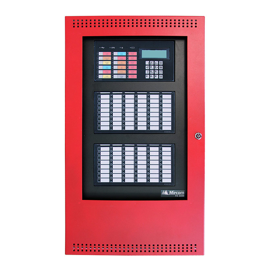
Mircom FX-3500RCU Configuration Manual (76 pages)
Fire Alarm Control Panel
Brand:
Mircom
| Category:
Control Panel
| Size: 5 MB
Table of Contents
Table of Contents
3
1 Installation
9
Installing the Configurator
9
Figure 1 Ftdichip CDM Drivers
9
Figure 2 Device Driver Installation Wizard
10
Figure 3 Completing the Device Driver Installation Wizard
10
Figure 4 MGC-3000 Series Configuration Utility Installshield Wizard
11
Figure 5 License Agreement
11
Figure 6 Choose Destination Location
12
Figure 7 Installshield Wizard Complete
12
Inserting the Wibu Key
13
Connecting the Cables
13
Figure 8 Security Key Logon
13
Figure 9 Picture of FX-3500 Board Showing USB Port
14
Figure 10 Picture of FX-3500 Board Showing Configurator Port
15
Starting the Windows Device Manager
16
Figure 11 Windows 8 Search Screen
16
Figure 12 System Properties
17
Configuring the Device Manager for USB
18
Figure 13 Device Manager
18
Figure 14 Microsoft Serial Ballpoint
18
Figure 15 Microsoft Serial Ballpoint Disabled
18
Figure 16 USB Serial Port in the Device Manager
19
Figure 17 USB Serial Port Properties
19
Figure 18 Port Settings
20
Figure 19 Advanced Settings
20
Configuring the Device Manager for a Serial Connection
21
Figure 20 COM Port in the Device Manager
21
Figure 21 Communications Port Properties
21
Figure 22 Port Settings
22
Figure 23 Advanced Settings
22
2 User Preferences
23
Figure 24 User Preferences Window
23
3 Overview
24
GUI - Major Components
24
Figure 25 GUI Panels
24
Related Documents
25
4 Menus
26
File Menu
26
Job Menu
26
Table 1 File Menu
26
Table 2 Job Menu
26
Insert Menu
27
Edit Menu
27
Table 3 Insert Menu
27
Panel Menu
28
Table 4 Edit Menu
28
Table 5 Panel Menu
28
Tools Menu
29
Table 6 Tools Menus
29
Quick Bar
30
Table 7 Quick Bar Icons
30
5 Job Tree and Details Pane
31
Job Details
31
Figure 26 Job Details
31
Figure 27 Holidays Window
33
Table 8 Timers
33
Base I/O
34
Loops
35
Figure 28 Base I/O Details
35
Table 9 Loop Details
35
Bypass Groups
36
Hazard Zones
36
Table 10 Flag Columns - F1, F2, F3
36
Table 11 Bypass Groups
36
Main Display
37
Display Adder
37
Table 12 Display Adder Info
37
Dialer
38
Common System Status
40
Input / Output Circuit Summary
41
6 Adding Items to the Job
42
Add Loop Controllers
42
Add Annunciator
42
Add Correlations
42
Figure 29 Add Correlations Window
42
Add Device
43
Figure 30 Add Devices Window
43
Add Display Adder
44
Figure 31 Add Display Adder Window
44
Deleting Correlations
45
Hazard Zones
45
Figure 32 Change Process Type Warning
45
7 Managing the Database
48
Backup Database
48
Restore Database
48
Figure 33 Backup Database
48
Figure 34 Restore Database
49
Figure 35 Restore Database
49
Compact Database
50
8 Managing Jobs
51
Create a New Job
51
Figure 36 Create Job Window
51
Open Job
52
Import Job
52
Figure 37 Select Job and Version Window
52
Figure 38 Import Job Window
52
Export Job
53
Figure 39 Export Job Window
53
New Version
54
Delete Job Version
54
Version History
54
Figure 40 Version History Window
54
Compare Job Versions
55
Figure 41 Select Job to Compare Window
55
Figure 42 Advanced Compare Options Window
57
Validate Job
58
Edit Job
58
Figure 43 the Job Is Protected against Unintentional Edits
58
Figure 44 this Job Version Has Already Been Built or Downloaded to the Panel
58
9 Working with the Panel
59
Connect
59
Figure 45 Connection Window
59
Send Job
60
Get Job
60
Panel Information
60
Event Log
61
Upgrade Firmware
62
Figure 46 Upgrade Firmware Wizard
62
Figure 47 Upgrade Firmware Wizard
62
10 Tools Menu
63
Extract All DB
63
Validate All
63
Build Job
63
Build Job Old Versions
63
Link Statistics
63
Log Send
63
Log Get
63
Log Comms
63
Trace
64
Display Structure
64
External Bus
64
About MGC-3000 Series Configuration Utility
64
Paste Special - Circuits, Adders or Entire Loops
65
Paste Special - Display Items, Display Adders or Annunciators
65
Figure 48 Paste Special
65
Figure 49 Paste Special
65
11 Correlations Pane
67
Input Circuit Correlations
67
Output Circuit Correlations
67
Figure 50 Correlations Pane
67
12 Differences Mode / Differences Report
68
Introduction
68
Primary Vs. Secondary Job
68
Initiating Differences Mode
68
Figure 51 Differences
69
13 Printing
70
Figure 52 Print
70
Print Setup
72
Figure 53 Print Setup
72
Advertisement
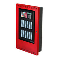
Mircom FX-3500RCU Installation And Operation Manual (103 pages)
Fire Alarm Control Panel
Brand:
Mircom
| Category:
Control Panel
| Size: 5 MB
Table of Contents
Table of Contents
3
Industry Canada and FCC Notice
7
Notice for All FX-3500RCU Series Built-In Udacts Sold in Canada
7
Industry Canada Notice
7
Notice for All FX-3500RCU Series Built-In Udacts Sold in the U.S.A
7
FCC Notice
8
Introduction
9
The FX-3500RCU Addressable Fire Alarm Control Panel
9
General Notes
10
FX-3500RCU Overview
11
FX-3500RCU Fire Alarm Control Panel Models
11
Figure 1 FX-3500RCU with DOX-1024DSR
11
FX-3500RCU System Components
12
Table 1 FX-3500RCU System Components
12
Related Documents
16
Installation
17
BBX-1024DS and BBX-1024DSR Mechanical Installation
17
Figure 2 BBX-1024DS and BBX-1024DSR Installation Instructions and Dimensions
17
Installation Tips
18
Installing Adder Modules
18
Figure 3 Main Board with All Adder Modules Installed
19
Main Board and Core Board Connectors and Jumpers
20
Figure 4 Port and Jumper Locations on Main Board
20
Table 2 Main Board Connectors and Jumpers
21
Table 3 Core Board Connectors and Jumpers (Plug-In Board in Center of Main Board)
21
Installing the PR-300 Polarity Reversal and City Tie Module
22
Figure 5 Jumper on Back of Display
22
Figure 6 Installing the PR-300 Polarity Reversal and City Tie Module
22
Installing the ALC-636 Dual Loop Adder
23
Figure 7 Installing the ALC-636 Dual Loop Adder
23
Table 4 PR-300 Polarity Reversal and City Tie Module Connectors and Jumpers
23
Table 5 ALC-636 Dual Loop Adder Connectors and Jumpers
23
Installing the RAX-1048TZDS Display Adder Module
24
Installing the IPS-2424DS Programmable Input Switches Module
24
Figure 8 IPS-2424DS Programmable Input Switches Module Front Chassis View
24
Installing the IPS-4848DS Programmable Input Switches Module
25
Figure 9 IPS-2424DS Cable Connections
25
Figure 10 IPS-4848DS Programmable Input Switches Module Front Chassis View
25
Figure 11 IPS-4848DS Cable Connections
26
Operation
27
Table 6 Settings Permitted in UL864
27
Table 7 Settings Permitted in CAN/ULC-S527 and CAN/ULC-S559
28
Addressable/Analog Devices
29
Figure 12 FX-3500RCU Configurator Date and Time Settings
30
Configurable Input Types
31
Table 8 Configurable Input Types
31
Output Types
35
Table 9 Configurable Output Types
35
NAC Circuit Operation
36
Single Stage Operation
37
Two-Stage Operation
38
Evacuation Codes
39
Positive Alarm Sequence
39
Remote Annunciator Operation
41
Figure 13 Enabling the Positive Alarm Sequence
41
Table 10 Annunciator Address DIP Switch Settings
41
Dialer Operation
42
Using the Operation Menu from the Control Panel
43
Figure 14 Operation Menu
44
Table 11 List Bypass Special Characters
57
Indication & Controls
62
Indication and Controls
62
LCD Display
62
Figure 15 LED Indicators and Control Buttons
62
Figure 16 Numeric Keypad
63
Table 12 Keypad and Cursor Button Descriptions
63
Common LED Indicators and Control Buttons
64
Table 13 LED Indicators and Control Buttons
64
Wiring
68
Wiring Tables
68
Table 14 Advanced Protocol and CLIP Devices Addressable Loop Wiring Table
68
Table 15 NAC and Auxiliary Power Circuits Wiring Table
69
Table 16 Releasing Circuits Wiring Table
69
Table 17 MIX-502MAP(A) Conventional Zone Module Input Circuit Wiring Table
69
Wire Routing
70
Figure 17 Wire Routing
70
Addressable Loop Wiring
71
Figure 18 Addressable Loop Wiring - Class B (Style 4)
71
Figure 19 Addressable Loop Wiring - Class a (Style 6)
71
NAC Circuit Wiring
72
Figure 20 Addressable Loop Wiring - Class X (Style 7)
72
Figure 21 NAC Circuit - Class B (Style Y) Wiring
73
Figure 22 NAC Circuit - Class a (Style Z) Wiring
73
Figure 23 RTI-1 Common Remote Trouble Indicator Wiring
74
Releasing Circuit Wiring
75
Figure 24 Releasing Circuit Wiring - Class B (Style Y) Wiring
76
Module and Devices Wiring
77
Figure 25 Wiring the Dialer
77
Figure 26 Connecting an FACP to a 3G4010 Interface Device in Canada
78
Figure 27 Connecting an FACP to a 3G4010CF Interface Device Outside Canada
79
Figure 28 Connecting an FACP to a SLE-LTEV or SLE-LTEA Interface Device Outside Canada
80
Figure 29 Wiring the PR-300 Polarity Reversal and City Tie Module
81
Power Supply Wiring
82
Table 18 Power Supply Electrical Ratings
82
Figure 30 Main Power Supply Wiring and Connections
83
Figure 31 Supervision of Auxiliary Supplies
84
System Checkout
85
Troubleshooting
85
Appendix A - Compatible Receivers
87
Table 19 Compatible DACR Receivers
87
Appendix B - Manual Panel Configuration
88
Appendix C - Reporting
94
Ademco Contact-ID FX-3500RCU Series Event Codes
94
Table 20 Contact-ID Event Codes
94
Security Industries Association SIA Format Protocol FX-3500RCU Series Event Codes
95
Table 21 SIA-DCS Event Codes
95
Appendix D - Specifications and Features
96
FX-3500RCU Fire Alarm Control Panel
96
Table 22 FX-3500RCU Specifications
96
FX-3500RCU System Module and Annunciator Specifications
97
Table 23 FX-3500RCU System Modules and Annunciator Specifications
97
Appendix E - Battery Calculations
98
Table 24 Recommended Batteries
99
Warranty and Warning Information
100
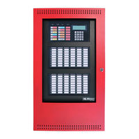
Mircom FX-3500RCU Application Manual (20 pages)
Fire Alarm Control Panel
Brand:
Mircom
| Category:
Control Panel
| Size: 2 MB
Table of Contents
Table of Contents
3
1 Operating the Panel
5
Hazard Zones
5
Counting Zone Type
5
Abort Type
5
Configurable Timers
6
Hazard Zone States
6
1.5.1 Hazard Idle
6
Hazard Alarm (Pre-Discharge)
7
1.5.3 Hazard Release
7
General Operation
7
2 Releasing Circuit Wiring
8
Releasing Circuit Wiring - Class B/Style y Wiring
8
3 Typical Releasing Applications
9
Pre-Action/Agent Release, Single Activation Application
9
Pre-Action/Agent Release, Double Activation Application
10
Pre-Action/Agent Release, Triple Activation Application
11
Pre-Action/Agent Release, 2 Input Type Activation Application
12
Deluge, Single Activation Application
13
Deluge, Double Activation Application
14
Deluge, Triple Activation Application
15
Deluge, 2 Input Type Activation Application
16
4 Compatible Solenoids
17
Advertisement
Advertisement
Related Products
Mircom FX-3318
Mircom FX-2000 series
Mircom FX-2003-6DS
Mircom FX-2017S-12ADS
Mircom FX-2009S-12DS
Mircom FX-2003-12XTDS
Mircom FX-2003-12DS
Mircom FX-2017-12ADS
Mircom FX-2200 Series
Mircom FX-400
Mircom Categories
Control Panel
Intercom System
Fire Alarms
Controller
Smoke Alarm
More Mircom Manuals
Login
Sign In
OR
Sign in with Facebook
Sign in with Google
Upload manual
Upload from disk
Upload from URL