Miller Electric Millermatic 350P Manuals
Manuals and User Guides for Miller Electric Millermatic 350P. We have 3 Miller Electric Millermatic 350P manuals available for free PDF download: Owner's Manual
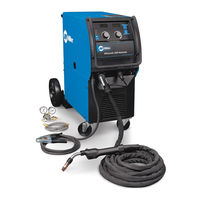
Miller Electric Millermatic 350P Owner's Manual (68 pages)
Brand: Miller Electric
|
Category: Welding System
|
Size: 1 MB
Table of Contents
Advertisement
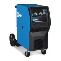
Miller Electric Millermatic 350P Owner's Manual (60 pages)
Arc Welding Power Source and Wire Feeder
Brand: Miller Electric
|
Category: Welding System
|
Size: 2 MB
Table of Contents
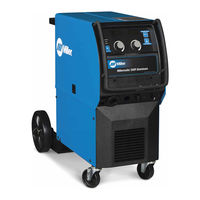
Miller Electric Millermatic 350P Owner's Manual (60 pages)
OM-1327
Brand: Miller Electric
|
Category: Welding System
|
Size: 1 MB
Table of Contents
Advertisement
Advertisement
Related Products
- Miller Electric Spoolmate 3545
- Miller Electric 350 VS
- Miller Electric Blu-Fab 3500
- Miller Electric ProHeat 35
- Miller Electric MILLERMATIC 35 SKP-35
- Miller Electric MILLERMATIC 35S
- Miller Electric Invision 354MP
- Miller Electric 3/32 WIRE
- Miller Electric Axcess 300
- Miller Electric MILLERMATIC 3OAN CONTROL/FEEDER