Sign In
Upload
Manuals
Brands
Metronix Manuals
Servo Drives
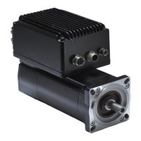
DIS-2 48/10 FB FS STO
User Manuals: Metronix DIS-2 48/10 FB FS STO Drive
Manuals and User Guides for Metronix DIS-2 48/10 FB FS STO Drive. We have
3
Metronix DIS-2 48/10 FB FS STO Drive manuals available for free PDF download: Manual, Mounting Instructions
Metronix DIS-2 48/10 FB FS STO Manual (88 pages)
Servo positioning controller
Brand:
Metronix
| Category:
Controller
| Size: 1 MB
Table of Contents
Table of Contents
4
1 General
8
Documentation
8
PROFIBUS Documentation
8
2 Safety Notes for Electrical Drives and Controllers
10
Used Symbols
10
General Notes
11
Danger Resulting from Misuse
12
Safety Notes
13
General Safety Notes
13
Safety Notes for Assembly and Maintenance
14
Protection against Contact with Electrical Parts
15
Protection against Electrical Shock by Means of Protective Extra-Low Voltage (PELV)16
16
Protection against Dangerous Movements
17
Protection against Contact with Hot Parts
17
Protection During Handling and Assembly
18
3 Wiring and Pin Assignment
19
Pin Assignment
19
PROFIBUS Cable
19
Figure 3.1: PROFIBUS Connector for DIS-2 48/10 FB
19
Termination and Bus Terminating Resistors
20
4 PROFIBUS-DP and Profidrive
21
Overview of DP and Its Different Versions
21
Basic Functions of DP-V0
22
Profidrive Overview
22
5 PROFIBUS Connection
24
Introduction
24
Figure 5.1: Example of the Telegram Format for the DIS-2 48/10 FB
24
Slave Overview
25
Master Overview
25
Figure 5.2: Hardware Configuration under SIEMENS S7
26
6 Telegram Editor
27
Introduction
27
Reception Telegrams
27
Figure 6.1: Composition of a Reception Telegram
28
Response Telegrams
29
Figure 6.2: Composition of a Response Telegram
30
7 Physical Units
31
Figure 7.1: Setting of Physical Units
31
Figure 7.2: Gear Ratio
32
8 Operating Parameters
34
PROFIBUS Operating Parameters
34
Figure 8.1: Setting of Operating Parameters
34
9 Device Control
36
Overview
36
Control Word 1
36
Status Word 1
40
State Diagram and Device Control
42
State Diagram
43
Figure 9.1: Simplified State Diagram
43
Device Control
44
Command Overview
46
10 Manufacturer-Specific Parameter Numbers
48
Overview
48
Pnus for Positioning Mode
50
PNU 1000: Position Set Number
50
PNU 1001: Position Data
50
PNU 1002: Start Set Number
52
PNU 1003: Position Profile Type
52
PNU 1050: Homing Method
53
PNU 1051: Home Offset
53
Figure 10.1: Interpretation of the Home Offset
54
Pnus for Speed Control Mode
55
PNU 1010: Target Velocity
55
PNU 1011: Accelerations for Velocity Control
55
Pnus for Different Operating Modes
57
PNU 1022: Current Limitiation
57
PNU 1040: Jogging
58
PNU 1290: Motor Data
58
PNU 1350: Enable Logic
59
Actual Values
60
PNU 1100: Position Actual Value
60
PNU 1101: Velocity Actual Value
60
PNU 1102: Current Actual Value
61
PNU 1140: Digital Outputs
61
PNU 1141: Digital Inputs
61
Parameters for the Telegram Structure
62
PNU 2000: PKW Access
62
PNU 2010: Placeholders
63
PNU 2011: Element 0
64
Parameter for Various Intents
65
PNU 1601: Last Error Code
65
PNU 1610: Error Managment
66
11 Operating Modes
67
Overview
67
Parameters
67
PNU 1500: Operating Mode
67
Speed Control Mode
68
Positioning Mode
68
Figure 11.1: Uninterrupted Sequence of Motion Tasks
69
12 Profile-Specific Parameter Numbers
70
Overview
70
PNU Description
70
PNU 971: Transfer into a Non-Volatile Memory
70
13 Function and Data Blocks for SIEMENS S7
71
Overview
71
Function and Data Blocks for DIS-2 48/10 FB Servo Positioning Controllers
72
Function Block (FB) Overview
72
Fbs of DIS-2 48/10 FB Servo Positioning Controllers
73
Fb_Position (FB 41 Positioning Mode)
73
Fb_Velocity (FB 43 Speed Control)
76
Integration of Fbs and Dbs
77
PROFIBUS Connection of DIS-2 48/10 FB Servo Positioning Controller
80
Reception Telegram of the Speed Control Example Project
80
Reception Telegram of the Positioning Example Project
82
Response Telegram for the Example Projects
83
Creating an S7 Program
84
Integrating the GSD File
84
Hardware Configuration
85
Integrating the Servo Positioning Controller
86
Overview of Function and Data Blocks
87
Advertisement
Metronix DIS-2 48/10 FB FS STO Mounting Instructions (48 pages)
Brand:
Metronix
| Category:
Servo Drives
| Size: 1 MB
Table of Contents
Table of Contents
3
1 General
5
Documentation
5
Scope of Supply
6
2 Safety Notes for Electrical Drives and Controllers
8
Used Symbols
8
General Notes
8
Danger Resulting from Misuse
10
Safety Notes
10
General Safety Notes
10
Safety Notes for Assembly and Maintenance
11
Protection against Electrical Shock by Means of Protective Extra-Low Voltage (PELV)
13
Protection against Dangerous Movements
13
Protection against Contact with Hot Parts
14
Protection During Handling and Assembly
14
3 Technical Data
15
Ambient Conditions and Qualification
15
Supply [X1]
16
Motor Connection [X301-X303]
16
Angle Encoder Connector [X2]
17
Communication Interfaces
18
STO Interface
20
Fieldbus Interfaces
21
4 Mechanical Installation
22
Important Notes
22
Position and Alignment of the Connectors
23
Connectors on the Main Board
23
Connectors for the Fieldbus Interfaces and RS232 Interface (Canopen, PROFIBUS or Ethercat)
23
Dimensions of the Housing
24
Mounting
26
5 Electrical Installation
30
Connection to Power Supply, Control and Motor
30
Connectors on the Basic Device DIS-2 48/10 FB FS STO
32
Connection: Power Supply and I/O [X1]
32
Connection: Motor [X301-X303]
34
Connection: Angle Encoder [X2]
34
Connection: Holding Brake [X3]
36
Connection: Brake Resistor [X304, X305]
37
Connection: Extension Port [X8]
38
Connection: Safe Torque off (STO) [X40] and [X40A]
40
Connectors Field Bus Modules DIS-2 48/10 FB FS STO
42
Connection: Serial Interface [X5]
42
Connection: Canopen [X401] and [X402]
43
Connection: PROFIBUS [X401] and [X402]
44
Connection: Ethercat [X401] and [X402]
45
6 Functional Safety Technology
46
General, Intended Use
46
Safety Indices
46
7 Emc-Compliant Cabling
47
Connection between the DIS-2 and the Motor
47
Connection between DIS-2 and Power Supply
48
Metronix DIS-2 48/10 FB FS STO Mounting Instructions (25 pages)
Decentral Intelligent Servo
Brand:
Metronix
| Category:
Servo Drives
| Size: 0 MB
Table of Contents
Safety Notes for Electrical Drives and Controllers
2
Danger Resulting from Misuse
3
General Safety Notes
4
Safety Notes for Assembly and Maintenance
4
Protection against Contact with Electrical Parts
6
Protection against Electrical Shock by Means of Protective Extra-Low Voltage (PELV)
7
Protection against Dangerous Movements
7
Protection against Contact with Hot Parts
8
Protection During Handling and Assembly
8
Technical Data
9
Mechanical Installation
12
Important Notes
12
Position and Alignment of the Connectors
13
Dimensions of the Housing
15
Electrical Installation
17
EMC-Compliant Wiring
23
Connection between DIS-2 and Power Supply
24
Advertisement
Advertisement
Related Products
Metronix DIS-2 310/2 FB FS STO
Metronix DIS-2 48/10 IC
Metronix 9019-3103-00
Metronix 9019-3103-04
Metronix 9019-3103-05
Metronix 9200-4104-2000
Metronix 9200-4104-3000
Metronix 9200-4840-2000
Metronix 9200-4840-3000
Metronix ARS 2000
Metronix Categories
Servo Drives
Controller
More Metronix Manuals
Login
Sign In
OR
Sign in with Facebook
Sign in with Google
Upload manual
Upload from disk
Upload from URL