Sign In
Upload
Manuals
Brands
Liebert Manuals
Control Unit
Liebert iCOM
Liebert Liebert iCOM Manuals
Manuals and User Guides for Liebert Liebert iCOM. We have
2
Liebert Liebert iCOM manuals available for free PDF download: User Manual
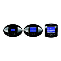
Liebert Liebert iCOM User Manual (84 pages)
Intelligent Communications & Monitoring System
Brand:
Liebert
| Category:
Control Unit
| Size: 2.56 MB
Table of Contents
Table of Contents
3
1 Introduction
7
Features
7
Figure 1 Liebert Icom Components
7
2 Liebert Icom Display Components and Functions
8
Figure 2 Liebert Icom Display Components
8
Table 1 Keyboard Icons and Functions
9
Table 1
9
Figure 3 Status Menu, Large Display, Graphical View
10
Figure 4 Liebert Icom Default Screen Symbols
10
Navigating through the Liebert Icom Menus
11
Control Interface
11
Accessing Submenus
11
Entering a Password
12
Figure 5 Menu Tree-Small Display, Stand-Alone or Networked
12
Figure 6 Menu Tree-Large Display, Stand-Alone
13
Viewing Multiple Units with a Networked Large Display
14
Figure 7 Menu Tree-Large Display, Networked
14
Figure 8 User Menu Icons
15
Table 9 Table
15
Table 11 Table
16
Figure 9 Service Menu Icons
17
Table 13 Table
17
3 Operation
18
Single Unit Functions
18
Unit/Fan Control
18
Figure 10 Start-Stop Priority Switches
18
Chilled Water Units with Variable Speed Motor
19
General Compressor Requirements
20
Compressor Timing-Units with Two Compressors
21
Compressor Sequencing
21
Motorized Ball Valve in Digital Scroll Units
22
MBV Operation after Compressor Is Turned off
22
Service Offset-Changing System Pressure Settings
22
Temperature Control-Single Source Cooling (no Extra Cooling Coil)
23
Temperature Proportional Band
23
Figure 11 Temperature Proportional Band
23
Compressor Control
24
Figure 12 One Single-Step Compressor Without Unloaders
24
Figure 13 Two Single-Step Compressors Without Unloaders or One Compressor with an Unloader
24
Figure 14 Two Compressors with Unloaders (Four-Step)
25
Figure 15 Digital Scroll Capacity Modulation, 10-100% Variable
26
Figure 16 Single and Dual Digital Scroll Compressor Activation Points
26
Chilled Water Control
27
Temperature Control-Second Cooling Source
27
Differential Temperatures / Controls (Comparator Circuit)
27
Figure 17 Three-Point Actuator Control (Example: Cooling)
27
Figure 18 Second Cooling Source and Compressorized Cooling
28
Temperature Control-Reheat
29
Three-Stage Electric, Hot Gas and Hot Water Reheat
29
Table 15 Table
29
Table 4 Reheat Configuration Types
29
Figure 19 Three-Stage Heating
30
SCR Reheat
31
Figure 20 Two Single-Step Compressors with SCR Reheat Set to Tight Mode
31
Figure 21 Two Single-Step Compressors with SCR Reheat Set to Standard Mode
32
Humidity Control
33
Figure 22 Humidity Proportional Band
33
Humidification
34
Table 17 Table
34
Table 5 Parameters for Infrared Humidifier Control
34
Dehumidification
35
Table 19 Table
35
Table 6 Dehumidification with Comp Settings
35
Control Types
36
Temperature and Humidity Control Types
36
Humidity Sensor Reading Control Types
37
Supply Limit-Optional
38
High and Low, Temperature and Humidity Events
38
User Inputs / Customer Inputs
39
Customer Inputs
39
Table 7
39
Event Types and Properties
40
Table 21 Table
41
Table 8 Possible Event Settings—Some Events Not Available in All Units
41
Possible Event Notifications
42
Table 23 Table
42
Table 9 Event Notifications—Large or Small Display
42
Next Maintenance Calculation
43
Calculation of Next Maintenance and Diagnostics
43
4 Teamwork
45
Teamwork Modes
45
Application of Teamwork Modes
45
No Teamwork
45
Teamwork Mode 1
45
Figure 23 Teamwork Mode 1 with Two Cooling Units
46
Teamwork Mode 2
47
Standby - Rotation
47
5 Installing a Liebert Icom Unit - to -Unit Network
48
Placement of Cooling Units
48
U2U Hardware: Cables and Network Switch
48
Wiring for Unit-To-Unit Communications-U2U
49
Table 10 Sample Liebert Icom Network Configurations
49
Table 25 Table
49
Figure 24 Connecting Two Cooling Units, each with a Small Display Using a Crossover Ethernet Cable
50
Wiring a Liebert Icom U2U Network
50
Figure 25 Wiring a Small Display for Stand-Alone Operation
51
Figure 26 Wiring a Small Display for U2U Network Operation
51
Figure 27 Wiring a Large Display for Stand-Alone Operation
52
Figure 28 Wiring a Large Display for U2U Network Operation
52
Figure 29 Liebert Icom Input-Output Control Board
53
Table 11 Ports Available for Connecting Liebert Icom Control Devices
53
External Communications-Building Management Systems, Liebert Sitescan
54
Figure 30 Liebert Vnsa with Optional Remote Large Display
54
6 Mounting a Large Display on a Wall
55
Location Considerations
55
Figure 31 Liebert Icom Display Dimensions
56
7 User Menu Parameters
57
Table 29 Table
57
Table 12 Setpoints Parameters
57
Table 13 Spare Part List Parameters—Large Display Only
57
Table 14 Event Log Parameters
57
Table 15 View Network Parameters—Large Display Only
57
Table 18 Active Alarms Parameters
59
Table 19 Display Setup Parameters
59
Table 22 Service Contacts Parameters
61
8 Service Menu Parameters
62
Table 23 Setpoints Parameters
62
Table
63
Table 25
64
Table 27 Diagnostics / Service Mode Parameters
67
Table 28 Set Alarms Parameters
69
Table 31 Network Setup Parameters
78
Table 32 Options Setup Parameters
79
Table 33 Service Contact Info Parameters
80
Table 29 Sensor Calibration / Setup Parameters
75
Table 30 System / Network Setup Parameters—Large Display Only
76
Advertisement
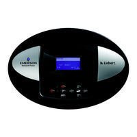
Liebert Liebert iCOM User Manual (80 pages)
Intelligent Communications & Monitoring
Brand:
Liebert
| Category:
Temperature Controller
| Size: 2.36 MB
Table of Contents
Table of Contents
3
1 Introduction
7
Features
7
Figure 1 Liebert Icom Components
7
2 Liebert Icom Display Components and Functions
8
Figure 2 Liebert Icom Display Components
8
Table 1 Keyboard Icons and Functions
9
Table 3 Table
9
Figure 3 Status Menu, Large Display, Graphical View
10
Figure 4 Liebert Icom Default Screen Symbols
10
Navigating through the Liebert Icom Menus
11
Control Interface
11
Accessing Submenus
11
Entering a Password
12
Figure 5 Menu Tree-Small Display, Stand-Alone or Networked
12
Figure 6 Menu Tree-Large Display, Stand-Alone
13
Viewing Multiple Units with a Networked Large Display
14
Figure 7 Menu Tree-Large Display, Networked
14
Figure 8 User Menu Icons
15
Table 2 User Menu Icons
15
Figure 9 Service Menu Icons
17
3 Operation
18
Single Unit Functions
18
Unit/Fan Control
18
Figure 10 Start-Stop Priority Switches
18
Chilled Water Units with Variable Speed Motor
19
General Compressor Requirements
20
Compressor Timing-Units with Two Compressors
21
Compressor Sequencing
21
Temperature Control-Single Source Cooling (no Extra Cooling Coil)
22
Temperature Proportional Band
22
Figure 11 Temperature Proportional Band
22
Compressor Control
23
Figure 12 One Single-Step Compressor Without Unloaders
23
Figure 13 Two Single-Step Compressors Without Unloaders or One Compressor with an Unloader (Two-Step)
23
Figure 14 Two Compressors with Unloaders (Four-Step)
24
Figure 15 Digital Scroll Capacity Modulation, 10-100% Variable
25
Figure 16 Single and Dual Digital Scroll Compressor Activation Points
25
Chilled Water Control
26
Temperature Control-Second Cooling Source
26
Differential Temperatures / Controls (Comparator Circuit)
26
Figure 17 Three-Point Actuator Control (Example: Cooling)
26
Figure 18 Second Cooling Source and Compressorized Cooling
27
Temperature Control-Reheat
28
Three-Stage Electric, Hot Gas and Hot Water Reheat
28
Table 4 Reheat Configuration Types
28
Figure 19 Three-Stage Heating
29
SCR Reheat
30
Figure 20 Two Single-Step Compressors with SCR Reheat Set to Tight Mode
30
Figure 21 Two Single-Step Compressors with SCR Reheat Set to Standard Mode
31
Humidity Control
32
Figure 22 Humidity Proportional Band
32
Humidification
33
Table 5 Parameters for Infrared Humidifier Control
33
Dehumidification
34
Table 6 Dehumidification with Comp Settings
34
Control Types
35
Temperature and Humidity Control Types
35
Humidity Sensor Reading Control Types
36
Supply Limit-Optional
37
High and Low, Temperature and Humidity Events
37
User Inputs / Customer Inputs
38
Table 7 Customer Inputs
38
Table 19 Table
38
Event Types and Properties
39
Table 21 Table
40
Table 8 Possible Event Settings—Some Events Not Available in All Units
40
Possible Event Notifications
41
Table 23 Table
41
Table 9 Event Notifications—Large or Small Display
41
Next Maintenance Calculation
42
Calculation of Next Maintenance and Diagnostics
42
4 Teamwork
44
Teamwork Modes
44
Application of Teamwork Modes
44
No Teamwork
44
Teamwork Mode 1
44
Figure 23 Teamwork Mode 1 with Two Cooling Units
45
Teamwork Mode 2
46
Standby - Rotation
46
5 Installing a Liebert Icom Unit - to -Unit Network
47
Placement of Cooling Units
47
U2U Hardware: Cables and Network Switch
47
Wiring for Unit-To-Unit Communications-U2U
48
Table 10 Sample Liebert Icom Network Configurations
48
Table 25 Table
48
Figure 24 Connecting Two Cooling Units, each with a Small Display Using a Crossover Ethernet Cable
49
Wiring a Liebert Icom U2U Network
49
Figure 25 Wiring a Small Display for Stand-Alone Operation
50
Figure 26 Wiring a Small Display for U2U Network Operation
50
Figure 27 Wiring a Large Display for Stand-Alone Operation
51
Figure 28 Wiring a Large Display for U2U Network Operation
51
Figure 29 Liebert Icom Input-Output Control Board
52
Table 11 Ports Available for Connecting Liebert Icom Control Devices
52
Table 27 Table
52
External Communications-Building Management Systems, Liebert Sitescan
53
Figure 30 Liebert Vnsa with Optional Remote Large Display
53
6 Mounting a Large Display on a Wall
54
Location Considerations
54
Figure 31 Liebert Icom Display Dimensions
55
7 U Mp
56
User
56
Menu
56
User Menu Parameter
56
Table 12 Setpoints Parameters
56
Table 13 Spare Part List Parameters—Large Display Only
56
Table 14 Event Log Parameters
56
Table 15 Graphics Parameters
57
Table 16 View Network Parameters—Large Display Only
57
Table 18 Sensor Data Parameters
58
Table 19 Active Alarms Parameters
58
Table 20 Display Setup Parameters
59
Table 21 Total Run Hours Parameters
59
Table 22 Timer Parameters—Sleep Mode
60
Table 23 Service Contacts Parameters
60
8 Service Menu Parameters
61
Table 24 Setpoints Parameters
61
Table 25 Unit Diary Parameters
62
Table 28 Diagnostics / Service Mode Parameters
66
Table 17 Set Alarms Parameters
69
Table 30 Set Alarms Parameters (Continued)
70
Table 29 Set Alarms Parameters
71
Table 31 Sensor Calibration / Setup Parameters
72
Table 32 System / Network Setup Parameters-Large Display Only
73
Table 33 Network Setup Parameters
74
Table 34 Options Setup Parameters
75
Table 35 Service Contacts Parameters
76
Advertisement
Related Products
Liebert itON 1000
Liebert itON 600 (India Version)
Liebert IntelliSlot
Liebert ITA 6kVA
Liebert IntelliSlot Web Card
Liebert IntelliSlot Web Card-LB
Liebert IntelliSlot IS-WEBADPT IntelliSlot IS-WEBCARD
Liebert IntelliSlot IS-WEBLB
Liebert IntelliSlot IS-WEBS
Liebert Integrated Secured Protection
Liebert Categories
UPS
Air Conditioner
Power Supply
Surge Protector
Chiller
More Liebert Manuals
Login
Sign In
OR
Sign in with Facebook
Sign in with Google
Upload manual
Upload from disk
Upload from URL