Sign In
Upload
Manuals
Brands
Lenze Manuals
Inverter
i700 Series
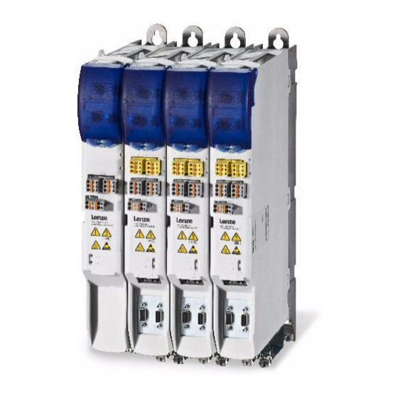
Lenze i700 Series Manuals
Manuals and User Guides for Lenze i700 Series. We have
6
Lenze i700 Series manuals available for free PDF download: Reference Manual, Hardware Manual, Mounting Instructions
Lenze i700 Series Reference Manual (359 pages)
servo inverter
Brand:
Lenze
| Category:
Inverter
| Size: 7 MB
Table of Contents
Table of Contents
2
1 About this Documentation
13
Conventions Used
14
Terminology Used
15
Definition of the Notes Used
16
Structure of the Parameter Descriptions
17
2 Parameter Handling
19
Parameter Transfer During Initialisation
19
Storage Parameter Set (Par001.*) and Total Parameter Set (Par000.*)
20
Saving a Parameter Set from the I700 to a File (Export)
21
Loading the Stored Parameter Set to the I700 (Import)
21
Monitoring of the Parameter Import (Error Report)
21
Cyclic Redundancy Check (CRC) - Parameter Set Comparison on the Basis of the Checksum
22
0X2030 - Parameter Set: Validity Check (CRC)
22
3 Communication with the Controller
23
Acceleration of the System (Initialisation)
23
Process Data (Cyclic PDO Transfer) and PDO Mapping
25
Synchronisation with "Distributed Clocks" (DC)
26
Parameter Data Transfer (SDO Communication)
27
Object Directory
27
SDO Abort Codes (Abort Codes)
28
ESI: Ethercat Slave Information File (Device Description)
28
Activating the Control Via PDO
29
0X2824 | 0X3024 - Device Control Via PDO: Activation
29
Lenze Control and Status Word
29
0X2830 | 0X3030 - Lenze Control Word
29
0X2831 | 0X3031 - Lenze Status Word
30
Ethernet over Ethercat (Eoe)
32
System Architecture
32
Supported Protocols and Services
33
Display of Eoe-Specific Information
33
0X2020 - Eoe Information
33
GCI-SDO Communication (TCP Port 9410)
34
Structure of the Ethercat Data Telegram
35
Assignment of User Data Areas P0
37
Error Codes
38
Telegram Example 1: Querying the Heatsink Temperature (Read Request)
39
Telegram-Example 2: Querying the Software Version of the I700 (Read Request)
41
Setting the LV Warning Threshold in the I700 (Write Request)
43
Telegram Example
43
4 Device Settings
45
Behaviour in Case of Error
45
0X10F1 ECAT: Behaviour in Case of Error
45
Device Identification Data
47
0X2000 - Device: Data
47
0X2001 - Device: Name
47
0X2100 - Brand Protection
47
Function "Optical Device Recognition
48
0X2021 - Device: Optical Recognition
48
Device Commands
48
0X2022 - Device Command
48
Monitoring of the DC-Bus Voltage
49
0X2540 - Device: Voltage Values
49
Resetting the "Undervoltage (LU)" Error Message
52
Real Time Information (Distributed Clock)
53
0X2580 - ECAT DC: Real-Time Information
53
5 Motor Control & Motor Settings
55
Required Commissioning Steps (Short Overview)
57
Servo Control for Synchronous Motor (SM)
57
Servo Control for Asynchronous Motor (ASM)
58
V/F Characteristic Control for Asynchronous Motor (ASM)
59
Commissioning Functions (Short Overview)
60
0X2822 | 0X3022 - Axis Command
60
0X2823 | 0X3023 - Axis Command: Progress
60
0X2825 | 0X3025 - Axis: Operating Mode
61
0X2832 | 0X3032 - Identification: Status Word
61
Enable/Inhibit Operation Via Control Word
62
Saving Changed Parameters Safe against Mains Failure
63
Wiring Check by Means of Manual Test Modes
64
0X2835 | 0X3035 - Manual Test Mode: Settings
64
Manual Test Mode "Voltage/Frequency
66
Manual Test Mode "Current/Frequency
67
Manual Control
69
0X2836 | 0X3036 - Manual Jog: Settings
71
Setting the Control Mode
73
0X2C00 | 0X3400 - Motor Control
73
Accepting/Adapting Plant Parameters
74
Compensating for Inverter Influence on Output Voltage
75
0X2947 | 0X3147 - Inverter Characteristic: Voltage Grid Points (y
76
0X2De0 | 0X35E0 - Advanced Settings
77
0X2947 | 0X3147 - Inverter Characteristic: Voltage Grid Points (Y)
78
Setting the Motor Parameters for the Servo Control
79
Lenze Motor: Easy Loading of Motor Data from the Catalogue Via the »PLC-Designer
79
Motors of Other Manufacturers or no Catalogue Data Available: Three Possibilities to Create the Setting
79
0X2C08 | 0X3408 - Motor: Setting Method - Motor Parameters
79
Enter Motor Nameplate Data
80
Set Motor Parameters Manually
80
Determine Motor Parameters Automatically Via "Motor Parameter Identification
82
Motor Parameters (Object Descriptions)
85
0X2C01 | 0X3401 - Motor: Common Parameters
85
0X2C03 | 0X3403 - Motor (SM): Parameter
87
0X2C02 | 0X3402 - Motor (ASM): Parameter
87
0X6075 | 0X6875 - Motor Rated Current
88
0X6076 | 0X6876 - Motor Rated Torque
88
Setting the Feedback System for the Servo Control
89
General Settings
90
0X2C45 | 0X3445 - Feedback System: Response to Open Circuit
90
0X2C46 | 0X3446 - Feedback System: Specifiable Number of Revolutions
90
0X2C5F | 0X345F - Feedback System: Parameter CRC
91
Settings for "Resolver" Version
91
0X2C43 | 0X3443 - Resolver: Number of Pole Pairs
91
0X2C44 | 0X3444 - Resolver Error Compensation: Parameter
92
Settings for "Encoder" Version
93
0X2C40 | 0X3440 - Encoder: Type
93
0X2C42 | 0X3442 - Encoder: Parameter
93
Evaluation of the Signal Quality
94
Additional Settings for Sincos Absolute Value Encoders with HIPERFACE® Protocol
96
0X2C41 | 0X3441 - Hiperface: Parameter
97
Detection of Changed Settings of the Feedback System
99
Synchronous Motor (SM): Pole Position Identification
100
Monitoring of the Pole Position Identification
101
0X2C60 | 0X3460 - Monitoring of Pole Position Identification: Response
101
Pole Position Identification PPI (360°)
101
Adapt Pole Position Identification PPI (360°)
106
0X2C61 | 0X3461 - Pole Position Identification PPI (360
108
Pole Position Identification PPI (Min. Movement)
109
0X2C62 | 0X3462 - Pole Position Identification PPI (Min. Movement
110
Pole Position Identification PPI (Without Movement)
112
0X2C63 | 0X3463 - Pole Position Identification PLI (Without Movement)
114
Setting Control Loops
115
Setting and Optimising the Current Controller
115
0X2941 | 0X3141 - Current Controller: Feedforward Control
117
0X2942 | 0X3142 - Current Controller: Parameter
117
0X2943 | 0X3143 - Motor: Current Setpoint - Filter Time
117
Manual Test Mode "Current Pulse
118
Determining the Total Moment of Inertia
121
0X2910 | 0X3110 - Moments of Inertia
122
Setting the Speed Controller
123
0X2900 | 0X3100 - Speed Controller: Parameter
124
0X2901 | 0X3101 - Speed Controller: Gain - Adaptation
124
0X2902 | 0X3102 - Speed Controller: Load Value I Component
124
0X2903 | 0X3103 - Speed: Speed Setpoint - Filter Time
124
0X2904 | 0X3104 - Speed: Actual Speed - Filter Time
125
Setting the Position Controller
126
0X2980 | 0X3180 - Position Controller: Gain
126
0X2981 | 0X3181 - Position Controller: Gain - Adaptation
126
0X2982 | 0X3182 - Position Controller: Output Signal Limitation
126
0X2983 | 0X3183 - Position: Select a New Actual Position
126
0X2984 | 0X3184 - Determine Target Position: Mode
127
Setting the Field Controller (ASM)
128
0X29C0 | 0X31C0 - Field Controller: Parameter
128
Setting the Field Weakening Controller (ASM)
129
0X29E0 | 0X31E0 - Field Weakening Controller: Parameter
129
0X29E1 | 0X31E1 - Field: Field Set Value Limitation
130
0X29E2 | 0X31E2 - DC Link Circuit Voltage: Filter Time
130
0X29E3 | 0X31E3 - Motor: Actual Voltage - Filter Time
130
0X29E4 | 0X31E4 - Voltage Reserve Range
130
Field Weakening Operation - Synchronous Motor (SM)
131
Fine Adjustment des Motor Model
132
Correction of the Stator Leakage Inductance (Lss)
132
0X2C04 | 0X3404 - Motor: Lss Saturation Characteristic - Inductance Grid Points (Y)
133
0X2C05 | 0X3405 - Motor: Lss Saturation Charcteristic - Reference for Current Grid Points (X
134
Example for Determining the Saturation Characteristic
135
Synchronous Motor (SM): Compensating for Temperature and Current Influences
138
0X2C06 | 0X3406 - Motor (SM): Magnet Characteristic (Current) - Grid Points
138
Asynchronous Motor (ASM): Identifying the Lh Saturation Characteristic
139
0X2C07 | 0X3407 - Motor (ASM): Lh Saturation Characteristic - Inductance Grid Points (Y)
140
Estimating the Optimal Magnetising Current
141
Parameterising Filter Elements in the Setpoint Path
142
Jerk Limitation
142
0X2945 | 0X3145 - Torque: Setpoint Jerk Limitation
142
Notch Filters (Band-Stop Filters)
142
0X2944 | 0X3144 - Torque: Notch Filter Setpoint Torque
144
Parameterising the V/F Characteristic Control
146
Defining the V/F Characteristic Shape
147
0X2B00 | 0X3300 - VFC: V/F Characteristic - Shape
147
0X2B01 | 0X3301 - VFC: V/F Characteristic - Define Reference Point
148
0X2B03 | 0X3303 - VFC: User-Definable V/F Characteristic - Voltage Grid Points (Y)
149
0X2B02 | 0X3302 - VFC: User-Definable V/F Characteristic - Frequency Grid Points (X
149
Torque Increase in the Lower Speed Range ("Boost" Function)
150
0X2B04 | 0X3304 - VFC: Voltage Vector Control - Setpoint Current
150
0X2B05 | 0X3305 - VFC: Voltage Vector Control Parameter
150
Setting the Voltage Boost
151
0X2B06 | 0X3306 - VFC: Voltage Boost
152
Setting the Load Adjustment
152
0X2B07 | 0X3307 - VFC: Load Adjustment Parameter
152
Defining the Behaviour at the Current Limit (Imax Controller)
153
0X2B08 | 0X3308 - VFC: Imax Controller - Parameter
154
Setting the Slip Compensation
155
0X2B09 | 0X3309 - VFC: Slip Compensation - Parameter
155
Setting the Oscillation Damping
156
0X2B0A | 0X330A - VFC: Oscillation Damping - Parameter
157
Optimising Pull-Out Slip Limitation
158
0X2B0C | 0X330C - VFC: Override Point of Field Weakening
158
Display Parameter
158
0X2B0B | 0X330B - VFC: Setpoint Frequency
158
Flying Restart" Function
159
0X2Ba0 | 0X33A0 - Flying Restart: Activate
159
0X2Ba1 | 0X33A1 - Flying Restart: Current
161
0X2Ba2 | 0X33A2 - Flying Restart: Start Frequency
161
0X2Ba3 | 0X33A3 - Flying Restart: Integration Time
161
0X2Ba4 | 0X33A4 - Flying Restart: Min. Deviation
161
0X2Ba5 | 0X33A5 - Flying Restart: Delay Time
161
0X2Ba6 | 0X33A6 - Flying Restart: Result
162
DC-Injection Braking" Function
163
0X2B80 | 0X3380 - DC-Injection Braking: Current
163
Short-Circuit Braking" Function
164
Setting the Switching Frequency
165
0X2939 | 0X3139 - Switching Frequency
165
Frequency and Speed Limitations
166
6 Holding Brake Control
168
Operating Modes
168
Triggering Via Control Word Via External Control (Lenze Setting)
168
Opening the Brake with a Starting Torque
169
Display of the Holding Brake Status
169
Overriding the Selected Brake Mode
169
Basic Signal Flow
169
No Brake Connected
169
Settings
171
Cia402 Device Profile
175
7 Cia402 Device Profile
176
Supported Drive Modes
177
Applied Units and Scaling for Position and Velocity
177
General Cia402 Parameters
178
0X60Fd 0X68Fd Digital Inputs
178
0X6404 0X6C04 Motor Manufacturer
178
0X6502 0X6D02 Supported Drive Modes
178
0X67Ff | 0X6Fff - Device Profile Number
179
Device Control
180
0X6040 | 0X6840 - Cia402 Controlword
180
0X6041 0X6841 Statusword
180
0X605A 0X685A Quick Stop Option Code
180
0X6060 | 0X6860 - Modes of Operation
181
0X6061 | 0X6861 - Modes of Operation Display
182
0X6085 | 0X6885 - Quick Stop Deceleration
182
Commands for the Device Status Control
183
Shutdown
184
Switching on
185
Enable Operation
186
Activate Quick Stop
187
Disable Operation
188
Disable Voltage
189
Fault Reset
190
Device States
191
Not Ready to Switch on
191
Switch on Disabled
194
Ready to Switch on
195
Switched on
196
Operation Enabled
196
Quick Stop Active
196
Fault Reaction Active
196
Fault
200
STO ("Safe Torque Off")
201
Selection of the Operating Mode
202
Parameters for the Scaling of Physical Values
202
0X607E | 0X687E - Polarity
203
0X6080 | 0X6880 - Max. Motor Speed
203
0X608F | 0X688F - Position Encoder Resolution
204
0X6090 | 0X6890 - Velocity Encoder Resolution
205
Parameters for Actuation of the Position Control
205
0X6062 | 0X6862 - Position Demand Value
206
0X6063 | 0X6863 - Position Actual Internal Value
207
0X6064 | 0X6864 - Position Actual Value
207
0X6065 | 0X6865 - Following Error Window
207
0X6066 | 0X6866 - Following Error Time out
207
0X6067 | 0X6867 - Position Window
208
0X6068 | 0X6868 - Position Window Time
208
0X60F4 | 0X68F4 - Following Error Actual Value
208
0X60Fa | 0X68Fa - Control Effort
208
0X60Fc | 0X68Fc - Position Demand Internal Value
208
Velocity Mode (Vl)
208
Default Mapping
208
Object Description
209
0X6042 | 0X6842 - Vl Target Velocity
210
0X6043 | 0X6843 - Vl Velocity Demand
210
0X6044 | 0X6844 - Vl Velocity Actual Value
211
0X6046 | 0X6846 - Vl Velocity Min Max Amount
211
0X6048 | 0X6848 - Vl Velocity Acceleration
211
0X6049 | 0X6849 - Vl Velocity Deceleration
211
Signal Flow (Servo Control)
211
Signal Flow (V/F Characteristic Control)
214
Cyclic Sync Position Mode (Csp)
217
Default Mapping
218
Object Description
219
0X607A | 0X687A - Target Position
220
0X60C0 | 0X68C0 - Interpolation Sub Mode Select
220
0X60C2 | 0X68C2 - Interpolation Time Period
220
0X60E0 | 0X68E0 - Positive Torque Limit Value
221
0X60E1 | 0X68E1 - Negative Torque Limit Value
221
Signal Flow
221
Control Commands & Status Information
223
Cyclic Sync Velocity Mode (Csv)
224
Default Mapping
225
Object Description
226
0X60B1 | 0X68B1 - Velocity Offset
227
Signal Flow (Servo Control)
227
0X60Ff | 0X68Ff - Target Velocity
229
Signal Flow (V/F Characteristic Control)
229
Control Commands & Status Information
231
Cyclic Sync Torque Mode (Cst)
232
Default Mapping
233
Object Description
234
0X2946 0X3146 Cyclic Sync Torque Mode: Speed Limitation
234
0X6072 0X6872 Max Torque
234
0X6073 0X6873 Max Current
234
0X6077 0X6877 Torque Actual Value
234
0X6078 0X6878 Current Actual Value
234
0X60B2 0X68B2 Torque Offset
234
Signal Flow
239
Control Commands & Status Information
241
Touch Probe (TP)
242
Default Mapping
243
General Functional Principle
244
Filtering the Touch Probe Signal
245
0X2500 - Touch Probe (TP): Debounce Time
245
Compensation of Runtime Delays
245
0X2D00 | 0X3500 - Touch Probe (TP): Dead Time Compensation
246
Touch Probe Function
246
0X60B8 | 0X68B8 - Touch Probe Function
246
Touch Probe Status
248
0X60B9 | 0X68B9 - Touch Probe Status
248
Time Stamps and Positions Detected
249
0X2D01 | 0X3501 - Touch Probe (TP): Time Stamp
249
0X60Ba | 0X68Ba - Touch Probe Pos1 Pos Value
249
0X60Bb | 0X68Bb - Touch Probe Pos1 Neg Value
249
0X60Bc | 0X68Bc - Touch Probe Pos2 Pos Value
249
0X60Bd | 0X68Bd - Touch Probe Pos2 Neg Value
250
8 Monitoring Functions
251
24-V Supply Voltage Monitoring
251
Monitoring of the Power Section and Device Utilisation (Ixt)
252
0X2D40 | 0X3540 - Ixt Utilisation
254
Monitoring of the Heatsink Temperature
255
Monitoring of the Motor Utilisation (I²Xt)
257
0X2D4E | 0X354E - Motor Utilisation (I²Xt): Motor Overload Warning Threshold
257
0X2D4F | 0X354F - Motor Utilisation (I²Xt): Actual Utilisation
257
0X2D50 | 0X3550 - Motor Utilisation (I²Xt): Motor Overload Error
257
0X2D4C | 0X354C - Motor Utilisation (I²Xt): Parameter for the Thermal Model
258
0X2D4D | 0X354D - Motor Utilisation (I²Xt): User-Definable Characteristic
261
Example of How to Enter the Characteristic for Standard and Servo Motors
262
UL 508-Compliant I²Xt Motor Overload Monitoring
264
Motor Temperature Monitoring
266
0X2D49 | 0X3549 - Motor Temperature Monitoring: Parameters
266
Spec. Charact. Curve for Motor Temperature Sensor
268
Motor Speed Monitoring
269
0X2D44 | 0X3544 - Motor Speed Monitoring
269
Motor Phase Failure Monitoring
270
0X2D45 | 0X3545 - Motor Phase Failure Detection
270
Limits of the Motor Phase Failure Monitoring
271
Monitoring 2: in the "Enable Operation" State Transition
272
Monitoring 1: in "Operation Enabled" Status
272
Monitoring with Regard to Short Circuit and Earth Fault
273
Monitoring of the Ultimate Motor Current
274
0X2D46 | 0X3546 - Monitoring: Ultimate Motor Current
274
Monitoring of the Position and Velocity Error
275
0X2D51 - Monitoring: Position and Velocity Error
275
Monitoring of the Position Error
276
Monitoring of the Speed Deviation
277
9 Diagnostics & Error Management
278
LED Status Displays
279
Indication of Fault and Warning (Error Code)
280
0X603F | 0X683F - Error Code
280
0X284F | 0X304F - Current Fault
280
Response of the Device in the Event of an Error
281
0X605E | 0X685E - Response to Error
282
0X2826 | 0X3026 - Quick Stop: Duration in the Event of a Fault
283
Resetting the Error/Fault
283
0X2840 | 0X3040 - Delay Time: Reset Error
283
0X2841 | 0X3041 - Reset Error
283
History Buffer
284
0X10F3 - Diagnostics: History Buffer
284
Cia402 Error Codes / Error Messages
286
Error Code 0Xff18: Communication Timeout in the Manual Control Mode
298
Error Code 0Xff19: Internal Error During Identification
298
Identification Data
299
0X1000 - Device: Type
299
0X1008 - ECAT: Manufacturer's Device Name
299
0X1009 - Device: Hardware Version
299
0X100A - Device: Software Version
299
0X1018 - ECAT: Identification Data
299
Diagnostics Parameters
300
0X10F8 - ECAT DC: Current Time
300
0X2D81 | 0X3581 - Counter: Operating Time
300
0X2D82 | 0X3582 - Motor: Actual Voltage - Veff, Phase-Phase
300
0X2D83 | 0X3583 - Motor: Phase Currents
300
0X2D8A | 0X358A - Speed Monitoring: Current Speed Error
301
Service/Internal
302
0X2Dd0 0X35D0 Field: Values
302
0X2Dd1 0X35D1 Motor: Currents
302
0X2Dd2 | 0X35D2 - Position: Target Position Interpolated
303
0X2Dd3 | 0X35D3 - Target Speeds
303
0X2Dd4 | 0X35D4 - Speed Controller: Output Signal
304
0X2Dd5 | 0X35D5 - Torque: Target Torque
304
0X2Dd6 | 0X35D6 - Torque: Filter Cascade
304
0X2Dd7 | 0X35D7 - Voltage Values
305
0X2Ddc | 0X35Dc - Slip: Actual Slip
306
0X2Ddd | 0X35Dd - Device: Actual Output Frequency
306
0X2Dde | 0X35De - Motor: Actual Position of Rotor Angle
306
0X2Ddf | 0X35Df - Axis: Device Data
307
Firmware Update
307
Reserved Objects
308
Appendix
309
Table of Attributes
309
Structure of the Parameter Set File
332
File Header
332
Data Header
333
Communication Objects
335
0X1600 - RPDO-->Axis A: Cyclic Sync Position Mode (Csp)
335
0X1601 - RPDO-->Axis A: Cyclic Sync Torque Mode (Cst)
336
0X1602 - RPDO-->Axis A: Cyclic Sync Velocity Mode (Csv)
336
0X1603 - RPDO-->Axis A: Velocity Mode (Vl)
336
0X1604 - RPDO-->Axis A: Touch Probe (TP)
336
0X1605 - RPDO-->Axis A: Freely Configurable (User)
337
0X1606 - RPDO-->Axis A: Torque Limits
337
0X1607 - RPDO --> Axis A: Speed Limits
337
0X1610 - RPDO-->Axis B: Cyclic Sync Position Mode (Csp)
337
0X1611 - RPDO-->Axis B: Cyclic Sync Torque Mode (Cst)
338
0X1612 - RPDO-->Axis B: Cyclic Sync Velocity Mode (Csv)
338
0X1613 - RPDO-->Axis B: Velocity Mode (Vl)
338
0X1614 - RPDO-->Axis B: Touch Probe (TP)
338
0X1615 - RPDO-->Axis B: Freely Configurable (User)
339
0X1616 - RPDO-->Axis B: Torque Limits
339
0X1617 - RPDO --> Axis B: Speed Limits
339
0X1A00 - Axis A-->TPDO: Cyclic Sync Position Mode (Csp)
339
0X1A01 - Axis A-->TPDO: Cyclic Sync Torque Mode (Cst)
340
0X1A02 - Axis A-->TPDO: Cyclic Sync Velocity Mode (Csv)
340
0X1A03 - Axis A-->TPDO: Velocity Mode (Vl)
340
0X1A04 - Axis A-->TPDO: Touch Probe (TP)
340
0X1A05 - Axis A-->TPDO: Freely Configurable (User)
341
0X1A06 - Axis A-->TPDO: Additional Status Information
341
0X1A10 - Axis B-->TPDO: Cyclic Sync Position Mode (Csp)
341
0X1A11 - Axis B-->TPDO: Cyclic Sync Torque Mode (Cst)
342
0X1A12 - Axis B-->TPDO: Cyclic Sync Velocity Mode (Csv)
342
0X1A13 - Axis B-->TPDO: Velocity Mode (Vl)
342
0X1A14 - Axis B-->TPDO: Touch Probe (TP)
343
0X1A15 - Axis B-->TPDO: Freely Configurable (User)
343
0X1A16 - Axis B-->TPDO: Additional Status Information
344
0X1C00 - Sync Manager: Communication Type
344
0X1C12 - Sync Manager 2 (RPDO-->Device): PDO Mapping
344
0X1C13 - Sync Manager 3 (RPDO-->Device): PDO Mapping
345
0X1C32 - Sync Manager 2 (RPDO-->Device): Parameter
345
0X1C33 - Sync Manager 3 (Device-->TPDO): Parameter
345
Licences
346
Index
347
Your Opinion Is Important to Us
358
Advertisement
Lenze i700 Series Hardware Manual (162 pages)
Servo-Inverter
Brand:
Lenze
| Category:
Inverter
| Size: 3 MB
Table of Contents
Table of Contents
3
1 About this Documentation
7
Document History
7
Conventions Used
8
Terms and Abbreviations Used
9
Notes Used
12
2 Safety Instructions
13
General Safety and Application Notes for Lenze Controllers
13
General Safety and Application Notes for Lenze Motors
16
Residual Hazards
18
3 Product Description
20
Device Features
20
Overview of the Devices
22
Supply Modules
22
Axis Modules
23
Identification
24
Product Key
25
4 Technical Data
27
General Data and Operating Conditions
27
Rated Data
31
External Supply Voltage
31
Busbar System for the DC Bus
33
Supply Modules
34
Axis Modules
38
Overcurrent Operation
42
Supply Modules
44
Axis Modules
44
Terminal Description
45
Supply Modules
45
Axis Modules
51
5 Mechanical Installation
66
Important Notes
66
Drilling the Holes into the Mounting Plate
67
Dimensions
68
Devices with Standard Built−In Design
68
Assembly in Standard Built−In Technique
69
Devices with "Cold Plate" Design
70
Mounting in "Cold Plate" Technique
71
Devices with Push−Through Design
76
Assembly in Push−Through Technique (Thermal Separation)
77
Notes on Mounting the Device Version in Push−Through Design
79
6 Electrical Installation
86
Important Notes
86
Electrical Isolation
87
Device Protection
87
Motor Protection
88
Interaction with Compensation Equipment
88
Safety Instructions for the Installation According to UL/CSA
89
Installation According to EMC (Installation of a Ce−Typical Drive System)
93
Shielding
93
Mains Connection, DC Supply
95
Motor Cable
96
Installation in the Control Cabinet
97
Wiring Outside of the Control Cabinet
99
Detecting and Eliminating EMC Interferences
100
Measures When Drive Is Used in IT Systems
101
Preparations
103
Integrated PE Conductor Connection
103
Integrated DC Bus Connection
104
Power Supply Modules
105
Axis Modules
107
7 DC−Bus Operation
110
Introduction
110
Terminology and Abbreviations Used
110
Advantages of a Drive System
110
Conditions for Trouble−Free DC−Bus Operation
111
Voltages
111
Number of Feeding Points
111
Other Conditions
111
DC−Bus Variants
112
Supply with One Power Supply Module
112
Supply with Power Supply Modules Operated in Parallel
113
Supply with Regenerative Power Supply Module
114
Rated Data
115
General Data
115
DC−Supply Power
115
DC−Power Requirements
117
Basic Dimensioning
118
General Information
118
Power Distribution of Controllers
119
Motor Efficiency
120
Power Loss of Devices
120
Determining the Power Requirements
120
Determining the Regenerative Power Requirements
120
Cable Protection
120
Braking Operation in a Drive System
121
Basic Considerations
121
EMC in DC−Bus Operation
122
Compliance with EMC Category C3 (Industrial Premises)
122
Compliance with EMC Category C2 (Residential Areas)
123
Assignment of Filters
123
8 Commissioning
125
Before Switching on
125
Quick Commissioning
125
9 Diagnostics
126
Display of Operating Data, Diagnostics
126
Supply Modules
126
Axis Modules
126
LED Status Displays
127
Supply Modules
127
Axis Modules
127
10 Safety Engineering
128
Introduction
128
Important Notes
129
Hazard and Risk Analysis
130
Standards
130
Mission Time
131
Acceptance
132
Description
132
Periodic Inspections
132
Certification
133
Basics for Safety Sensors
134
Basic Safety − STO
135
Mode of Operation
135
Technical Data
136
Electrical Installation
138
11 Accessories (Overview)
139
Overview
139
Mains Chokes
140
RFI Filter/Mains Filter
142
External Brake Resistors
143
Power Supply Units
144
Terminals
145
Components for Operation in the DC−Bus Connection
154
Installation Material for the Push−Through Technique
155
EMC Accessories
156
Shield Mounting
156
12 Appendix
158
Total Index
158
Lenze i700 Series Mounting Instructions (20 pages)
Single- / Double-Inverter
Brand:
Lenze
| Category:
Inverter
| Size: 0 MB
Advertisement
Lenze i700 Series Mounting Instructions (20 pages)
Single- / Double−Inverter
Brand:
Lenze
| Category:
Servo Drives
| Size: 0 MB
Lenze i700 Series Mounting Instructions (19 pages)
Single-/Double-Inverter
Brand:
Lenze
| Category:
Inverter
| Size: 1 MB
Lenze i700 Series Mounting Instructions (18 pages)
Brand:
Lenze
| Category:
Power Supply
| Size: 0 MB
Advertisement
Related Products
Lenze Teachware i7000
Lenze i750
Lenze i550-C1.5/230-2
Lenze i550-C2.2/230-1
Lenze i55AE137B
Lenze I55AE F Series
Lenze I51AE F Series
Lenze I55BE311F
Lenze I55APB Series
Lenze i55AE215D
Lenze Categories
DC Drives
Control Unit
Inverter
Engine
Controller
More Lenze Manuals
Login
Sign In
OR
Sign in with Facebook
Sign in with Google
Upload manual
Upload from disk
Upload from URL