Sign In
Upload
Manuals
Brands
Kontron Manuals
Single board computers
CompactPCI CP6000
User Manuals: Kontron CompactPCI CP6000 Slot Processor
Manuals and User Guides for Kontron CompactPCI CP6000 Slot Processor. We have
1
Kontron CompactPCI CP6000 Slot Processor manual available for free PDF download: User Manual
Kontron
CompactPCI CP6000
User Manual
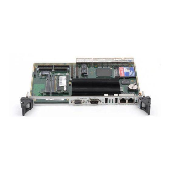
Kontron CompactPCI CP6000 User Manual (238 pages)
6U Pentium M PICMG 2.16 CPU Blade
Brand:
Kontron
| Category:
Single board computers
| Size: 6 MB
Table of Contents
Table of Contents
4
User Guide
2
ID 27942
13
Introduction
24
Board Overview
25
Board-Specific Information
26
System Relevant Information
27
System Expansion Capabilities
27
CP6000 Functional Block Diagram
28
Board Diagrams
28
CP6000 4 HP Front Panels
29
CP6000 Board Layout (Front View)
30
CP6000 Board Layout (Reverse View)
31
CP6000 4HP Version Main Specifications
32
Technical Specification
32
Kontron Software Support
38
Standards
39
Related Publications
40
Functional Description
44
Intel® Pentium® M Core Voltage in the Various Frequency Modes
45
Maximum Power Dissipation of Intel® Pentium® M (CPU Only)
45
Supported Intel® Pentium® M Processors on the CP6000
45
Maximum Power Dissipation of Intel® Celeron® M (CPU Only)
46
Memory Options Utilizing SODIMM Sockets
46
855GME Chipset Functional Block Diagram
47
GME Chipset Overview
47
Graphics and Memory Controller Hub (855GME)
48
Peripherals
49
Supported Intel® Celeron® M Processor on the CP6000
46
SM Bus Device Addresses
50
Reset
50
EEPROM Address Map
51
Thermal Management/System Monitoring
51
Board Interfaces
52
Keyboard Connector J24 Pinout
53
USB Connectors J7 and J8 Pinout
53
Keyboard Connector J24
53
USB Connectors J7 and J8
53
Keyboard/Mouse Interface
53
Graphics Controller
54
D-Sub CRT Con. J10
55
D-Sub CRT Connector J10 Pinout
55
Serial Port Con. J9 (COM1) Pinout
56
Serial Port Con. J9 (COM1)
56
COM Ports
56
Dual Gigabit Ethernet Connector J6A/B
57
EIDE Interface Connectors J19 and J20
58
EIDE Interfaces
58
Connecting an Onboard 2.5" HDD to CP6000 Via Parallel ATA
59
Pinout of ATA 44-Pin Connector J19
60
Pinout of ATA 40-Pin Connector J20
61
Compactflash Connector J17 Pinout
62
SATA Connector J18 Pinout
63
Extension Con. J12
63
SATA Connector J18
63
Extension Connector J12
63
SATA Extension Connector J30 Pinout
64
SATA Extension Connector J31 Pinout
64
SATA Extension Connectors J30 and J31
64
Connecting an Onboard 2.5" SATA HDD to CP6000-EXT-SATA
65
PMC Connectors J25, J26, J27 and J28
66
PMC Interface
66
PMC Connectors J26 and J28 Pinouts
67
PMC Connectors J25 and J27 Pinouts
68
Compactpci Interface
69
Coding Key Colors on J1
71
Compactpci Bus Connector
71
Compactpci Bus Connector J1 System Slot Pinout
72
Compactpci Bus Connector J1 Peripheral Slot Pinout
73
Bit Compactpci Bus Connector J2 System Slot Pinout
74
Bit Compactpci Bus Connector J2 Peripheral Slot Pinout
75
Compactpci Rear I/O Connector J3 Pinout
76
Compactpci Rear I/O Connector J3 Signals
77
Compactpci Rear I/O Connector J4 Pinout
78
Compactpci Rear I/O Connector J5 Pinout
79
IPMI Functional Block Diagram
81
Intelligent Platform Management Interface
81
IPMI Glossary
82
IPMI Implementation on the CP6000
83
Compactpci Rear I/O Connector J5 Signals
79
Compactpci Sensors
84
Data Repositories
85
Reset Control
84
Installation
88
CP6000 Initial Installation Procedures
89
Standard Removal Procedures
90
Peripheral Hot Swap Procedure
91
Installation of CP6000 Peripheral Devices
92
Rear I/O Device Installation
93
Software Installation
94
Clearing BIOS CMOS Setup
98
Compactflash Configuration
98
Shorting Chassis GND (Shield) to Logic GND
98
General Purpose LED Setting
99
VGA CRT Rear I/O Configuration
99
VGA-CRT Jumper Setting
99
Resistor Setting to Configure COM1
100
COM1 Configuration Jumpers and Resistors
100
Serial Ports COM1 and COM2 Jumper and Resistor Settings
100
Jumper Setting for RS-422 RXD Termination (COM1)
101
Jumper Setting for RS-422 TXD and RS-485 Termination (COM1)
101
Resistor Setting to Configure COM2
102
COM2 Configuration Jumpers and Resistors
102
Jumper Setting for RS-422 RXD Termination (COM2)
103
Jumper Setting for RS-422 TXD and RS-485 Termination (COM2)
103
Interrupts
104
Onboard PCI Interrupt Routing
105
Memory Map for the 1St Megabyte
106
I/O Address Map
107
IPMI Configuration Register
108
Special Registers Description
108
IPMI Interrupt Configuration Register
109
Watchdog
109
Watchdog Timer
110
Geographic Addressing Register
111
Watchdog, Compactpci Interrupt Configuration Register
112
CPCI Master Reset Register
113
I/O Status Register
114
Hot Swap Control Register
115
Hardware Index
115
LED Control Register
116
Logic Version
116
Hot Swap LED Control Register
117
Power Consumption
122
DC Operational Input Voltage Ranges
124
Power Consumption
124
Backplane
125
Maximum Input Power Voltage Limits
124
Input Voltage Characteristics
126
Start-Up Ramp of the CP3-SVE180 AC Power Supply
127
Power Consumption
127
Power Consumption: DOS
128
Power Consumption: Windows® 2000 100% CPU Usage
128
Real Applications
128
Power Consumption: Windows® 2000 IDLE Mode
128
Power Consumption Table for CP6000 Accessories
129
Testing Application
129
Power Consumption: Windows® 2000 3D Mark Benchmark
129
Power Consumption: Windows® 2000 Intel® High Power Tool
129
System Considerations
132
CPU External Thermal Supervision
133
Thermal Management Recommendations
134
Intel® 82546 Dual Gigabit Ethernet Controller Power Supply
135
Forced Air Flow
135
Pentium® M Temp. Vs. Airspeed Graph with Standard Heat Sink
136
Pentium® M Temp. Vs. Airspeed Graph with E2 Heat Sink
136
Peripherals
137
A. CTM80-2 RIO Module
140
CTM80-2 RIO Module, 4HP Variant
141
CP6000-EXT-SATA Module Main Specifications
144
CP6000-EXT-SATA Module Functional Block Diagram
144
CP6000-EXT-SATA Module Layout
145
B.5 Module Interfaces
146
Board-To-Board Connector J1 Pinout
146
Board-To-Board Connector J3 Pinout
146
SATA Connector J2 Pinout
147
SATA Connector J2
147
B.5.2 SATA Connector J2
147
Table of Contents
154
Chapter 1 Starting CP6000
160
Starting CP6000
160
CP6000 Setup Menu
161
Navigation
161
Navigation, Continued
162
Navigation, Continued
163
Chapter 2 Main Setup
164
System Time/System Date
164
Chapter 3 Advanced BIOS Setup
166
Advanced BIOS Setup
167
Cpu Configuration Screen
167
CPU Configuration Settings
167
Intel® Speedstep™ Tech
167
Advanced BIOS Setup
168
IDE Configuration
168
Ide Configuration Screen
168
IDE Configuration Settings
168
Advanced BIOS Setup, Continued
169
Hard Disk Drive Write Protect
169
IDE Detect Time out (Seconds)
169
Primary, Secondary, Third and Fourth IDE Master and Slave
169
Advanced BIOS Setup, Continued
170
ATA (PI) 80-Pin Cable Detection
170
Advanced BIOS Setup, Continued
171
Primary, Secondary, Third and Fourth IDE Master and Slave Settings
171
Primary, Secondary, Third and Fourth Ide Master and Slave Sub Menu
171
Advanced BIOS Setup, Continued
172
Drive Parameters
172
Lba/Large Mode
172
Type
172
Advanced BIOS Setup, Continued
173
Block (Multi-Sector Transfer)
173
PIO Mode
173
Advanced BIOS Setup, Continued
174
DMA Mode
174
S.M.A.R.T. for Hard Disk Drives
174
Advanced BIOS Setup, Continued
175
32Bit Data Transfer
175
ARMD Emulation Type
175
Advanced BIOS Setup, Continued
176
Floppy Configuration Screen
176
Floppy Configuration Settings
176
Advanced BIOS Setup, Continued
177
Floppy Drive A: and B
177
Onboard Floppy Controller
177
Advanced BIOS Setup, Continued
178
Super Io Configuration Screen
178
Advanced BIOS Setup, Continued
179
Serial Port1 Address
179
Serial Port2 Address
179
Advanced BIOS Setup, Continued
180
ACPI Aware O/S
180
Acpi Configuration Screen
180
Advanced BIOS Setup, Continued
181
ACPI 2.0 Feature
181
ACPI APIC Support
181
Advanced ACPI Configuration
181
AMI OEMB Table
181
Apic Acpi Sci Irq
181
General ACPI Configuration
181
Repost Video on S3 Resume
181
S4 BIOS Support
181
Suspend Mode
181
Advanced BIOS Setup, Continued
182
Aml
182
Headless Mode
182
Rsdt
182
Advanced BIOS Setup, Continued
183
Clear Event Log
183
Event Log Configuration Screen
183
Mark All Events as Read
183
PCI Error Logging
183
View Event Log
183
Advanced BIOS Setup, Continued
184
IPMC Watchdog Time out
184
IPMC Watchdog Timer Action
184
IPMI 1.5 Configuration
184
Ipmi 1.5 Configuration Screen
184
Advanced BIOS Setup, Continued
185
Dual Port IPMB Redundancy
185
Kcs-Sms Irq
185
Management Controller Configuration
185
Advanced BIOS Setup, Continued
186
SMBIOS Configuration
186
Smbios Configuration Screen
186
SMBIOS SMI Support
186
Advanced BIOS Setup, Continued
187
Remote Access
187
Remote Access Configuration
187
Remote Access Configuration Screen
187
Serial Port Number
187
Advanced BIOS Setup, Continued
188
Flow Control
188
Redirection after BIOS POST
188
Serial Port Mode
188
Terminal Type
188
VT-UTF8 Combo Key Support
188
Advanced BIOS Setup, Continued
189
Legacy USB Support
189
USB Configuration
189
Usb Configuration Screen
189
USB Function
189
Advanced BIOS Setup, Continued
190
USB 2.0 Controller
190
USB 2.0 Controller Mode
190
USB Mass Storage Device Configuration
190
Chapter 4 Pci/Pnp Setup
192
Plug and Play O/S
192
Pci/Pnp Setup, Continued
193
Allocate IRQ to PCI VGA
193
Palette Snooping
193
PCI Latency Timer
193
Pci/Pnp Setup, Continued
194
Irq
194
Offboard PCI/ISA IDE Card
194
PCI IDE Busmaster
194
Pci/Pnp Setup, Continued
195
Dma
195
Reserved Memory Size
195
Chapter 5 Boot Setup
196
Boot Setup, Continued
197
Boot Settings Configuration
197
Quick Boot
197
Quiet Boot
197
Boot Setup, Continued
198
Add-On ROM Display Mode
198
Boot-Up Num-Lock
198
PS/2 Mouse Support
198
Wait for 'F1' if Error
198
Boot Setup, Continued
199
Hit 'DEL' Message Display
199
Interrupt 19 Capture
199
Boot Setup, Continued
200
Boot Device Priority
200
Nd Boot Device
200
Rd Boot Device
200
St Boot Device
200
Boot Setup, Continued
201
Hard Disk Drives
201
Boot Setup, Continued
202
Removable Devices
202
Boot Setup, Continued
203
CD/DVD Drives
203
Chapter 6 Security Setup
204
CP6000 Password Support
204
Remember the Password
204
Two Levels of Password Protection
204
Security Setup, Continued
205
Supervisor Password
205
User Password
205
Security Setup, Continued
206
Boot Sector Virus Protection
206
Change Supervisor Password
206
Change User Password
206
Clear User Password
206
Security Setup, Continued
207
Change User Password
207
Clear User Password
207
Chapter 7 Chipset Setup
208
Chipset Setup, Continued
209
Intel Montara-GML NORTHBRIDGE CONFIGURATION
209
Chipset Setup, Continued
210
Southbridge Configuration
210
Chapter 8 OEM Feature
212
OEM Feature, Continued
213
Clock Spreading
213
OEM Feature, Continued
214
PC Health
214
OEM Feature, Continued
215
Auto Thermal Throttling
215
Automatic Thermal Monitor
215
CPU Performance
215
P4 Term Trip 125°C/257F
215
Temperature Monitor
215
OEM Feature, Continued
216
Etherboot ROM
216
Lan Boot
216
OEM Feature, Continued
217
Board Version
217
EKS Index
217
Geographic Addressing
217
Hardware Index
217
Ident Number
217
Logic Index
217
Serial Number
217
System INFO
217
System Slot
217
OEM Feature, Continued
218
Accept Class Code FF
218
Delay for PCI Config Cycle
218
Pci
218
OEM Feature, Continued
219
IRQ5 Routing
219
Watchdog
219
Watchdog Mode
219
WD Active Time
219
OEM Feature, Continued
220
Active for Boot
220
Fail Signal
220
Chapter 9 Power Setup
222
Power Management/Apm
222
Power Savings under AC
222
Power Savings Level
222
Suspend Time out (Minute)
222
Power Button Mode
222
Power Setup, Continued
223
PME Resume
223
RI Resume
223
USB Controller Resume
223
Chapter 10 Exit Menu
224
Save Changes and Exit
224
Exit Menu, Continued
225
Discard Changes
225
Discard Changes and Exit
225
Exit Menu, Continued
226
Load Optimal Defaults
226
Exit Menu, Continued
227
Load Fail-Safe Defaults
227
Chapter 11 Deleting a Password
228
Erase Old Password
228
Chapter 12 POST Codes
230
Bootblock Initialization Code Checkpoints
230
Bootblock Recovery Code Checkpoints
231
POST Code Checkpoints
232
POST Code Checkpoints, Continued
233
DIM Code Checkpoints
234
Index
236
Advertisement
Advertisement
Related Products
Kontron COMe Ref. Carrier-i T10 TNIV
Kontron COMe Ref. Carrier-i T10 TNIE
Kontron COMe-bCL6
Kontron COMe-cBW6
Kontron COMe-cAP6
Kontron COMe-cRP6 E2
Kontron COMe-mAS10 E2 Series
Kontron COMe-mAS10 E2x7211RE 4G/32G
Kontron COMe-mAS10 E2x7835RE 8G/32G
Kontron CP6006X-SA
Kontron Categories
Computer Hardware
Motherboard
Server
Industrial PC
Desktop
More Kontron Manuals
Login
Sign In
OR
Sign in with Facebook
Sign in with Google
Upload manual
Upload from disk
Upload from URL