Sign In
Upload
Manuals
Brands
Kollmorgen Manuals
Control Unit
Digital MMC Control
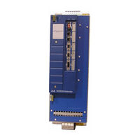
User Manuals: Kollmorgen Digital MMC Control System
Manuals and User Guides for Kollmorgen Digital MMC Control System. We have
1
Kollmorgen Digital MMC Control System manual available for free PDF download: Hardware Manual
Kollmorgen Digital MMC Control Hardware Manual (322 pages)
Brand:
Kollmorgen
| Category:
Control Unit
| Size: 5 MB
Table of Contents
Table of Contents
5
1 Introduction to the MMC Smart Drive
11
Overview
11
Contents of this Manual
11
Software and Manuals
11
Required Software and Manuals
11
Suggested Manuals
11
Kollmorgen Support Contact
13
2 Safety Precautions
15
System Safety
15
User Responsibility
15
Safety Instructions
15
Safety Signs
16
Warning Labels
16
Safety First
17
Safety Inspection
17
Before Starting System
17
After Shutdown
17
Operating Safely
18
Electrical Service & Maintenance Safety
18
Safe Cleaning Practices
19
3 Installing the MMC Smart Drive
21
Storing the Drive before Installation
21
Unpacking the Drive
21
Handling an MMC Smart Drive
21
Inspecting the Drive before Installation
21
Complying with European Directives
22
Conforming with UL and Cul Standards
22
General Installation and Ventilation Requirements
22
Controlling Heat Within the System
23
Bonding
24
Bonding a Subpanel Using a Stud
24
Bonding a Ground Bus Using a Stud
24
Bonding a Ground Bus or Chassis Using a Bolt
24
Grounding Multiple Drive Cabinets
25
Bonding Multiple Subpanels
25
Drive Mounting Guidelines
25
Drive System Grounding Procedures
26
Grounding Multiple Drives in the same Cabinet
29
System Wiring Guidelines
29
Recommended Signal Separation
30
Building Your Own Cables
32
Routing Cables
32
Wiring the Drive
32
Sizing the 24V Power Supply
32
System AC Power Wiring Guidelines
33
Connecting Interface Cables
34
Preparing Motor Connection Wires
35
4 System Power Devices
39
AC Input Power Requirements
39
Protection
41
Motor Overload Protection
41
Motor Thermal Protection
41
230V Smart Drive Protection Requirements
41
Smart Drive Protection Requirements
42
Line Reactors
46
Specifications and Dimensions for Required Line Reactors
47
Isolation Transformers
53
External Shunts
54
Choosing External Shunts
54
Mounting External Shunts
56
Connecting Shunt Modules
63
1-Phase MMC Smart Drive Shunt Wiring
63
3-Phase MMC Smart Drive (-SD) Shunt Wiring
64
Line Filters
65
Line Filters and CE Compliance
65
Dimensions for 230V Line Filters
71
Dimensions for 460V Line Filters
72
1/3 Phase MMC Smart Drive
73
Control Section Connectors, Switches, Leds
75
Leds
75
Picpro Port (Digital Interfaced Drives)
75
Picpro Port (Analog Drives)
77
Node Address Rotary Switch (Digital Interfaced MMC-SD Only)
80
Digital Link Ports (Digital Interfaced MMC-SD Only)
81
Feedback Connectors (F1 & F2)
83
Feedback Connectors (F1 and F2) Details
88
Feedback Port (F1/F2) to Motor Cables
92
Drive I/O Connector (IO)
104
Power Section Connectors
111
24 VDC In/Brake Connector
112
EN" Requirements and Safe-Off Operation
113
Power Connector
114
DC Bus/Regen Connector (3-Phase Drive Only)
117
Specifications - 230V MMC Smart Drive
118
General Data for All 230V Models
118
Physical and Electrical Data for 230V Drives
121
Dimensions for 230V MMC Smart Drive
122
Phase MMC Smart Drive Nextgen
129
Control Section Connectors, Switches, Leds
132
Status Display
132
Node Address Rotary Switches
132
Digital Link Ports
133
Feedback Connectors (F1 & F2)
135
Feedback Connectors (F1 and F2) Details
140
Feedback Port (F1/F2) to Motor Cables
145
Drive I/O Connectors (IO1 & IO2)
150
Power Section Connectors
154
DC Power Connector
154
EN" Requirements and Safe-Off Operation
154
AC Power Connector
155
Line Fusing
155
Motor/Brake Connector
156
Motor/Brake Cables
158
Motor Chokes
158
DC Bus/Regen Connector
159
Bus/Regen Connections
159
External Regen Resistors
159
Specifications - 460V MMC Smart Drive Nextgen
161
General Data
161
Physical and Electrical Data
165
Dimensions
166
3-Phase MMC Smart Drive
169
Control Section Connectors, Switches, Leds
169
Power Section Connectors
169
Size 1 Power Section Connectors
169
Shunt/DC Bus Connector
171
AC Power Connector
172
Motor Connector
172
Power Connector (J1)
173
Motor Brake Connector (X101)
174
Size 2 Power Section Connectors
174
AC Power Connector
176
Motor Connector
177
Power Connector (J1)
178
Size 3 Power Section Connectors
179
AC Power Connector
181
Motor Connector
182
Power Connector (J1)
183
Motor Brake Connector (X101)
184
Size 4 Power Section Connectors
184
AC Power Connector
186
Motor Connector
187
Power Connector (J1)
188
Motor Brake Connector (X101)
189
Fan Connector (X36)
190
Typical 460V Drive Connection Layout
191
Specifications - 460V MMC Smart Drive)
192
Common Data for Size 1, 2, 3, 4 (All Models)
192
Physical/Electrical Data for 460V Size 1 Smart Drives
195
Physical/Electrical Data for 460V Size 2 Smart Drives
197
Physical/Electrical Data for 460V Size 3 Smart Drives
200
Physical/Electrical Data for 460V Size 4 Smart Drives
203
Dimensions for the 460V Smart Drives
206
8 S200-DLS Drive
215
S200-DLS Option Card
217
LED Indicators
217
Diagnostic Indicator Details
217
Digital Link Leds
217
Node Address Rotary Switches
218
Digital Link Ports
219
Auxiliary Feedback Port
221
Drive I/O and I/O Power Ports
229
Drive I/O Port Details
231
Drive I/O Port Outputs
232
Drive I/O Port Inputs
232
Drive I/O Port Wiring Example
232
Power Section Wiring Accessories
233
Specifications - S200-DLS Drive
235
9 Motor Cables & Connectors
237
Flex Cable Installation Guidelines
237
Bending Radius
237
Cable Tension
238
Flex Cable Installation
238
AKM/DDR Motor Power Cables
240
LSM/MSM Motor Connector Kits
241
LSM/MSM Motor Power Cables
242
LSM/MSM Motor Fan Cables
245
10 Maintenance and Troubleshooting
247
Maintenance
247
Troubleshooting
248
General Troubleshooting
248
Power LED
248
Power-On Diagnostics
248
Run-Time Diagnostics
248
Troubleshooting with the Diagnostic LED (D1)
249
Troubleshooting with the 7-Segment Display
249
Troubleshooting Using the Status LED (STATUS)
257
11 Resolver Interface Option Module
261
Theory of Operation
261
Installing the Resolver Module
261
12 Drive Resident Digital MMC Control
265
Introduction
265
Overview
265
Major Components
265
Installing the Drive Resident Digital MMC Control
267
Installing into a 230V MMC-SD Drive
267
Installing into a 460V MMC-SD Drive
267
System Wiring Guidelines
268
Starting an Operation
269
Connecting the Drive Resident Digital MMC Control to the Application
269
Basic Setup and Maintenance Procedures
269
Start-Up Diagnostics
270
Power LED
270
Scan LED
270
Drive Resident Digital MMC Control Start-Up Diagnostic Leds
271
MMC Run-Time Diagnostics
272
Connectors & Operation
273
Picpro Port (P1)
273
Block I/O Port (C1)
273
User Port
277
Ethernet Port
283
General I/O Port (C5)
285
DC Output Operation
290
DC Input Operation
292
Specifications
294
13 Declarations of Conformity
297
A 460V MMC Smart Drive DC Bus Sharing
303
Introduction
303
DC Bus Sharing with AC Power to All Drives
303
DC Bus Sharing with AC Power to One Drive
305
B 460V MMC Smart Drive DC Bus Sharing
309
Introduction
309
DC Bus Sharing with AC Power to All Drives
309
DC Bus Sharing with AC Power to One Drive
311
Index
315
Sales and Service
321
Advertisement
Advertisement
Related Products
Kollmorgen MMC Smart Drive
Kollmorgen MKD Series
Kollmorgen MKD-C
Kollmorgen MKD-N
Kollmorgen MMC Smart Drive Series
Kollmorgen MMC-SD-1.3-460
Kollmorgen MMC-SD-2.4-460
Kollmorgen MMC-SD-4.0-460
Kollmorgen MMC-SD-6.0-460
Kollmorgen MMC-SD-8.0-460
Kollmorgen Categories
Servo Drives
Amplifier
Touch terminals
DC Drives
Engine
More Kollmorgen Manuals
Login
Sign In
OR
Sign in with Facebook
Sign in with Google
Upload manual
Upload from disk
Upload from URL