Table of Contents
Advertisement
Advertisement
Table of Contents
Troubleshooting

Related Manuals for Kollmorgen MMC Smart Drive

Summary of Contents for Kollmorgen MMC Smart Drive
- Page 1 © Smart Drive and Digital MMC Control Hardware Manual Version 6.0 Catalog No. M.1301.5524 Part No. M.3000.1329 IND. CONT. EQ. 12KP Keep all product manuals as a product component during the life span of the product. Pass all product manuals to future users/owners of the product.
- Page 3 All rights reserved. No part of this work may be reproduced in any form (by printing, photocopying, microfilm or any other method) or processed, copied or distributed by electronic means without the written permission of Kollmorgen. Kollmorgen - December 2011...
- Page 4 The text and illustrations are not binding in detail. Kollmorgen shall not be liable for any technical or editorial omissions occurring in this document, nor for any consequential or incidental damages resulting from the use of this document.
-
Page 5: Table Of Contents
MMC Smart Drive Hardware Manual TABLE OF CONTENTS Table of Contents Table of Contents..........................3 1 Introduction to the MMC Smart Drive..................... 9 1.1 Overview........................... 9 1.2 Contents of This Manual......................9 1.3 Software and Manuals......................9 1.3.1 Required Software and Manuals..................9 1.3.2 Suggested Manuals ...................... - Page 6 4.5.1 Choosing External Shunts .................... 52 4.5.2 Mounting External Shunts .................... 54 4.5.3 Connecting Shunt Modules ..................61 4.5.3.1 230V, 1-Phase MMC Smart Drive Shunt Wiring ..........61 4.5.3.2 460V, 3-Phase MMC Smart Drive (-SD) Shunt Wiring........62 4.6 Line Filters..........................63 4.6.1 Line Filters and CE Compliance ...................
- Page 7 6.2.3.2 Motor Chokes ....................156 6.2.4 DC Bus/Regen Connector...................157 6.2.4.1 Bus/Regen Connections ..................157 6.2.4.2 External Regen Resistors ..................157 6.3 Specifications - 460V MMC Smart Drive NextGen ...............159 6.3.1 General Data.......................159 6.3.2 Physical and Electrical Data..................163 6.4 Dimensions...........................164 7 460V 3-Phase MMC Smart Drive ....................167 7.1 Control Section Connectors, Switches, LEDs ..............167...
- Page 8 MMC Smart Drive Hardware Manual TABLE OF CONTENTS 8.1.7 Drive I/O and I/O Power Ports ..................227 8.1.8 Drive I/O Port Details ....................229 8.1.8.1 Drive I/O Port Outputs..................230 8.1.8.2 Drive I/O Port Inputs..................230 8.1.8.3 Drive I/O Port Wiring Example ................230 8.2 Power Section Wiring Accessories ..................
- Page 9 12.5.5.2 DC Input Operation..................290 12.6 Specifications ........................292 13 Declarations of Conformity .......................295 A 460V MMC Smart Drive DC Bus Sharing ...................301 A.1 Introduction ..........................301 A.2 DC Bus Sharing with AC Power to All Drives...............301 A.3 DC Bus Sharing with AC Power to One Drive..............303 B 460V MMC Smart Drive DC Bus Sharing ...................307...
- Page 10 MMC Smart Drive Hardware Manual TABLE OF CONTENTS Kollmorgen - Decamber 2011...
-
Page 11: Introduction To The Mmc Smart Drive
INTRODUCTION TO THE MMC SMART DRIVE Introduction to the MMC Smart Drive Overview This manual covers four distinct products: The Analog and Digital Interfaced 230V MMC Smart Drive (MMC-SD). The 230V • Smart Drive is detailed exclusively in Chapter 5 on page 71 •... - Page 12 MMC Smart Drive Hardware Manual INTRODUCTION TO THE MMC SMART DRIVE • Ethernet Application Specific Function Block Manual General Purpose Application Specific Function Block • Manual Kollmorgen - December 2011...
-
Page 13: Kollmorgen Support Contact
MMC Smart Drive Hardware Manual INTRODUCTION TO THE MMC SMART DRIVE Kollmorgen Support Contact Contact your local Kollmorgen representative for: • Sales and order support • Product technical training • Warranty support • Support service agreements Kollmorgen Technical Support can be reached: In the United States, telephone (800) 558-4808 •... - Page 14 MMC Smart Drive Hardware Manual INTRODUCTION TO THE MMC SMART DRIVE Kollmorgen - December 2011...
-
Page 15: Safety Precautions
Safety Precautions READ AND UNDERSTAND THIS SECTION IN ITS ENTIRETY BEFORE UNDERTAKING INSTALLATION OR ADJUSTMENT OF THE MMC SMART DRIVE AND ANY ASSOCIATED SYSTEMS OR EQUIPMENT The instructions contained in this section will help users to operate and maintain the equipment in a safe manner. -
Page 16: Safety Signs
MMC Smart Drive Hardware Manual SAFETY PRECAUTIONS ATTENTION Do not touch the main power supply fuses or any com- ponents internal to the power modules while the main power supply switch is ON. Note that when the main power switch is OFF, the incoming supply cable may be live. -
Page 17: Safety First
These notices provide information intended to prevent potential pe sonal injury. Safety First Kollmorgen equipment is designed and manufactured with consideration and care to generally accepted safety standards. However, the proper and safe performance of the equipment depends upon the use of sound and prudent operating, maintenance and servicing procedures by trained personnel under adequate supervision. -
Page 18: Operating Safely
MMC Smart Drive Hardware Manual SAFETY PRECAUTIONS Operating Safely Do not operate the control system until you read and understand the operating • instructions and become thoroughly familiar with the system and the controls. • Never operate the control system while a safety device or guard is removed or... -
Page 19: Safe Cleaning Practices
MMC Smart Drive Hardware Manual SAFETY PRECAUTIONS • Make sure the circuit is safe by using the proper test equipment. Check test equip- ment regularly. ATTENTION Care should be taken if you are manually discharging the bus capacitors. WARNING Even after power to the drive is removed, it may take up to 10 minutes for bus capacitors to discharge to a level below 50 VDC. - Page 20 MMC Smart Drive Hardware Manual SAFETY PRECAUTIONS • Always clean up spills around the equipment immediately after they occur. Never attempt to clean a control system while it is operating. • Never use water to clean control equipment unless you are certain that the equip- •...
-
Page 21: Installing The Mmc Smart Drive
If you find damage, either concealed or visible, contact your buyer to make a claim with the shipper. If degraded performance is detected when testing the unit, contact your distributor or Kollmorgen. Do this as soon as possible after receipt of the unit. Kollmorgen - December 2011... -
Page 22: Complying With European Directives
Metal debris or other foreign matter can become lodged in the cir- cuitry, which can result in damage to components. The MMC Smart Drive is suitable for operation in a pollution degree 2 environment (i.e., normally, only non-conductive pollution occurs). Install the drive away from all sources of strong electromagnetic noise. -
Page 23: Controlling Heat Within The System
MMC Smart Drive. This protects the MMC Smart Drive from both heat and electri- cal noise. The MMC Smart Drive itself is a source of heat, though in most installations its heat dissipates without harmful effects. System heat is generated from power dissipated •... -
Page 24: Bonding
• line reactors • CAUTION If the MMC Smart Drive is operated outside the recommended environmen- tal limits, it may be damaged. This will void the warranty. Bonding Connecting metal chassis, assemblies, frames, shields and enclosures to reduce the effects of electromagnetic interference (EMI) is the process of bonding. -
Page 25: Grounding Multiple Drive Cabinets
3.10 Drive Mounting Guidelines • A control cabinet for the MMC Smart Drive should have a NEMA-12 rating or bet- ter. A cabinet with this rating protects its contents from dust and mechanical dam- age. •... -
Page 26: Drive System Grounding Procedures
3.11 Drive System Grounding Procedures The ground of the MMC Smart Drive power source must be connected directly to a Single Point Ground (SPG) tie block. The tie block should be made of brass or copper, bolted or brazed to the control cabinet. If the tie block is bolted rather than brazed, scrape away paint or grease at the point of contact. - Page 27 You must ensure that the “0V” or “Common” of all devices connected to the MMC Smart Drive are connected to Single Point Ground (SPG). Failure to do so may result in erratic operation or damage to the MMC Smart Drive and devices connected to it. Examples of devices connected to the MMC Smart Drive include the power source that supplies power to the MMC Smart Drive and devices connected to the MMC Smart Drive PiCPro Port.
- Page 28 MMC Smart Drive Hardware Manual INSTALLING THE MMC SMART DRIVE 3.11.1 Grounding Requirements Figure 3-1: Example of Grounding Required for CE Compliant Single Phase 230V Drive System In-coming AC Power (Mains) In-coming Supply Ground Terminal ENCLOSURE Supply Circuit Disconnecting 24V Power...
-
Page 29: Grounding Multiple Drives In The Same Cabinet
3.12 System Wiring Guidelines The MMC Smart Drive relies on electrical signals to report what is going on in the application and to send commands to it. In addition, signals are constantly being Kollmorgen - December 2011... -
Page 30: Recommended Signal Separation
MMC Smart Drive Hardware Manual INSTALLING THE MMC SMART DRIVE exchanged within the system. The MMC Smart Drive is designed for use in industrial environments, but some guidelines should be followed. This section contains common system wiring configurations, size, and practices that can be used in a majority of applications. - Page 31 MMC Smart Drive Hardware Manual INSTALLING THE MMC SMART DRIVE WARNING: FEEDBACK DEVICE DAMAGE Feedback Cable Installation and Removal All power to the Smart Drive (24 Vdc and main AC power) must be removed before connecting/disconnecting feedback cable connectors at the Smart Drive (F1 and F2 connector) or at the motor feedback device.
-
Page 32: Building Your Own Cables
Maintain the least amount of unshielded cable leads. 3.13 Wiring the Drive These procedures assume you have bonded and mounted your MMC Smart Drive to the subpanel and that there is no power applied to the system. 3.13.1 Sizing the 24V Power Supply When you size your power supply, you must ensure that the supply is large enough to handle the total load. -
Page 33: System Ac Power Wiring Guidelines
(due to improper wiring or 24 VDC supply failure), a fuse should be used in series with the 24 VDC to the MMC Smart Drive. Specifi- cally, a 4 A max. “UL248 Series” fuse should be used. In addition, the 24 VDC shall be supplied by an isolating source such that the maximum open circuit voltage available to the MMC Smart Drive is not more than 30 VDC. -
Page 34: Connecting Interface Cables
MMC Smart Drive Hardware Manual INSTALLING THE MMC SMART DRIVE • Use shielded cables and AC line filters (for CE Compliance). Make sure that wir- ing from the drive to the line filter is as short as possible. Locate common ground- ing bus bars as close as possible to the drive. -
Page 35: Preparing Motor Connection Wires
Preparing Motor Connection Wires NOTE It is recommended that Kollmorgen cables be used. Kollmorgen cables are designed to minimize EMI and are recommended over hand-built cables. 1. Strip back cable jacket approximately 152 mm (6.0 in.) from the end of the cable. - Page 36 MMC Smart Drive Hardware Manual INSTALLING THE MMC SMART DRIVE 6. Gently pull on each wire to make sure it does not come out of its terminal. Rein- sert and tighten any loose wires. 7. Attach the plastic cover to terminal block...
- Page 37 MMC Smart Drive Hardware Manual INSTALLING THE MMC SMART DRIVE Figure 3-5: Terminating Incoming AC Power (Mains) Cable for 460V SD Drive FROM MAINS Cable Jacket Shield Clamp Screw Shield Clamped to Mounting Panel Clamp Screw Maximum 10 cm from...
- Page 38 MMC Smart Drive Hardware Manual INSTALLING THE MMC SMART DRIVE Figure 3-6: Terminating Power Cables for 460V SDN Drive Drive Shield Bracket Cable Clamp Cable Note: Shield Bracket, Cable Clamp(s), Cable(s) are installed by User Kollmorgen - December 2011...
-
Page 39: System Power Devices
MMC Smart Drive Hardware Manual SYSTEM POWER DEVICES System Power Devices AC Input Power Requirements The MMC Smart Drive is powered from an external AC power source. The power required for each drive type is listed in Table 4-1. Kollmorgen - December 2011... - Page 40 MMC Smart Drive Hardware Manual SYSTEM POWER DEVICES Table 4-1: AC Input Power Requirements Requirements Nominal Transformer Input Current Amps Drive Model 1-phase (3-phase) 1-phase (3-phase) Input Input Input Input Voltage = Voltage = Voltage = Voltage = 230 Volt Drives...
-
Page 41: Protection
MMC Smart Drive Hardware Manual SYSTEM POWER DEVICES Protection 4.2.1 Motor Overload Protection The MMC Smart Drive utilizes solid state motor overload protection in accordance with UL508C that operates: • within 8 minutes at 200% overload • within 20 seconds at 600% overload 4.2.2... -
Page 42: Smart Drive Protection Requirements
MMC Smart Drive Hardware Manual SYSTEM POWER DEVICES • meet both of the requirements for a non-restricted fuse (above) be a Class RK1, J, or CC dual element current limiting fuse • Table 4-2: 230V Smart Drive Protection Devices Maximum Fuse Size... - Page 43 MMC Smart Drive Hardware Manual SYSTEM POWER DEVICES The requirements for both restricted and non restricted fuses may be meet by using one of two methods: • Use a single fuse that meets all requirements. The easiest way to accomplish this is to use a “Combination Fuse”...
- Page 44 This is the maximum fuse size that can be used for Device and Branch Circuit Protection. Kollmor- gen recommends the use of HSJ or DFJ fuses only. d. Kollmorgen part numbers for these fuses can be found in Table 4-4 on page 43 e.
- Page 45 MMC Smart Drive Hardware Manual SYSTEM POWER DEVICES Table 4-4: Available Fuses & Holders Fuse Part Fuse Holder Fuse Holder Combination Fuse Number Type 3P Part Number DFJ6 M.3000.0190 30 Amp M.1016.1046 DFJ10 M.3000.1321 30 Amp M.1016.1046 DFJ15 M.3000.0191 30 Amp M.1016.1046...
-
Page 46: Line Reactors
SYSTEM POWER DEVICES Line Reactors AC Line Reactors are required when using some models of the MMC Smart Drive. They protect the drive from impermissible rates of current change and reduce harmonic current distortions. When required, they are mounted between the drive and the mains input power source. -
Page 47: Specifications And Dimensions For Required Line Reactors
MMC Smart Drive Hardware Manual SYSTEM POWER DEVICES 4.3.1 Specifications and Dimensions for Required Line Reactors Table 4-5: MMC-SD-12-460 Line Reactor Specifications Fundamental Power Part Inductance Weight Amperage Loss Number 1.2 mH 14 lbs. M.1302.7373 0.38 x 0.75 3.00 (4 SLOTS) 3.43... - Page 48 MMC Smart Drive Hardware Manual SYSTEM POWER DEVICES Table 4-6: MMC-SD-16-460 Line Reactor Specifications Fundamental Power Part Inductance Weight Amperage Loss Number 0.8 mH 16 lbs. M.1302.7374 0.38 x 0.75 3.00 (4 SLOTS) 4.00 WIRE RANGE: 22-5 AWG LABEL 2.63...
- Page 49 MMC Smart Drive Hardware Manual SYSTEM POWER DEVICES Table 4-7: MMC-SD-24-460 Line Reactor Specifications Fundamental Power Part Inductance Weight Amperage Loss Number 0.7 mH 28 lbs. M.1302.7375 0.38 x 0.75 3.00 (4 SLOTS) 4.75 LABEL 3.16 WIRE RANGE: 18-4 AWG...
- Page 50 MMC Smart Drive Hardware Manual SYSTEM POWER DEVICES Table 4-8: MMC-SD-30-460 Line Reactor Specifications Fundamental Power Part Inductance Weight Amperage Loss Number 0.5 mH 27 lbs. M.3000.0105 Kollmorgen - December 2011...
- Page 51 MMC Smart Drive Hardware Manual SYSTEM POWER DEVICES Table 4-9: MMC-SD-42-460 Line Reactor Specifications Fundamental Power Part Inductance Weight Amperage Loss Number 0.4 mH 51 lbs. M.3000.0106 Kollmorgen - December 2011...
- Page 52 MMC Smart Drive Hardware Manual SYSTEM POWER DEVICES Table 4-10: MMC-SD-51-460 Line Reactor Specifications Fundamental Power Part Inductance Weight Amperage Loss Number 100A 0.3 mH 51 lbs. M.3000.0107 Kollmorgen - December 2011...
-
Page 53: Isolation Transformers
M.3000.0108 Isolation Transformers The MMC Smart Drive does not require the use of isolation transformers. However, a transformer may be required to match the voltage requirements of the controller to the available service. To size a transformer for the main AC power inputs, the power output (KVA) of each axis must be known. -
Page 54: External Shunts
External Shunts Power from the motor is returned to the MMC Smart Drive during motor deceleration. Excessive power may have to be dissipated from the MMC Smart drive when large inertia loads are present. External shunts should be used to avoid excessive bus over voltage faults. - Page 55 MMC Smart Drive Hardware Manual SYSTEM POWER DEVICES W x T = Watts/sec or Joules where: W is watts from Step 1 above, T is decel time required by the application 3. Obtain the Absorption Energy in Joules for the drive from the Specifications sec- tion of the drive manual.
-
Page 56: Mounting External Shunts
MMC Smart Drive Hardware Manual SYSTEM POWER DEVICES Table 4-12: Shunt Resistors Part Shunt Resistor Module For Drive Number For Single Phase Drives: M.1015.7046 100Ω, 300W, 600V, Dynamic MMC-SD-0.5-230 MMC-SD-1.0-230 MMC-SD-2.0-230 For Three Phase Drives: MMC-SD-3.0-230 M.3000.0503 30Ω, 300W Cont. Power. 215mm(L) x 60mm(W) x 30mm(H) 145Ω, 450W Cont. - Page 57 MMC Smart Drive Hardware Manual SYSTEM POWER DEVICES EXTERNAL SHUNTS ON SMART DRIVE NEXTGEN (SDN) DRIVES For a detailed description of shunts these shunts, refer to the Kollmorgen "AKD/S700 Accessories Manual" which can be found at www.kollmor- gen.com. Kollmorgen - December 2011...
- Page 58 MMC Smart Drive Hardware Manual SYSTEM POWER DEVICES Figure 4-2: Mounting Dimensions for 230V External Shunt (P/N M.1015.7046) 2.56 65.10 1.50 CLEARANCE HOLES FOR #10 38.10 13.30 (M5) SCREWS. [6.30] 18.60 6.30 NOTE: 1. ALLOW 3.0” (76.2 mm) CLEARANCE IN FRONT OF UNIT FOR CABLES.
- Page 59 MMC Smart Drive Hardware Manual SYSTEM POWER DEVICES Figure 4-3: Mounting Dimensions for 460V External Shunt (P/N M.1302.7048) 20.71 in. (526 mm) 0 5, 5 x 8 2.52 in. (64 mm) 3.66 in. (93 mm) 23.82 in. (605 mm) Figure 4-4: Mounting Dimensions for 460V External Shunt (P/N M.1302.7049) 0 5, 5 x 8 24.65 in.
- Page 60 MMC Smart Drive Hardware Manual SYSTEM POWER DEVICES Figure 4-6: Mounting Dimensions for 460V External Shunt (P/N M.1302.7061) 13.62 in. (346 mm) 19.80 in. (503 mm) 13.38 in. (340 mm) 20.70 in. (526 mm) 11.81 in. (300 mm) 21.65 in. (550 mm) 5.91 in.
- Page 61 MMC Smart Drive Hardware Manual SYSTEM POWER DEVICES Figure 4-7: Mounting Dimensions for 460V External Shunt (P/N M.1302.7063) 13.62 in. (346 mm) 19.80 in. (503 mm) 13.38 in. (340 mm) 20.70 in. (526 mm) 11.81 in. (300 mm) 21.65 in. (550 mm) 5.91 in.
- Page 62 MMC Smart Drive Hardware Manual SYSTEM POWER DEVICES Figure 4-8: Mounting Dimensions for Reduced Size Panel mount Shunts Kollmorgen - December 2011...
-
Page 63: Connecting Shunt Modules
Do not connect more than two shunt modules to an MMC Smart Drive. 4.5.3.1 230V, 1-Phase MMC Smart Drive Shunt Wiring The 230V, 1-Phase MMC Smart Drive requires the use of an Active Shunt module. Refer to Figure 4-9 for wiring an Active Shunt Module to this drive. -
Page 64: 3-Phase Mmc Smart Drive (-Sd) Shunt Wiring
Front of Drive 4.5.3.2 460V, 3-Phase MMC Smart Drive (-SD) Shunt Wiring The 460V, 3-Phase MMC Smart Drive requires the use of a Passive Shunt module (regen resistor). Refer to Figure 4-11 for wiring an Passive Shunt Module to this drive. -
Page 65: Line Filters
MMC Smart Drive Hardware Manual SYSTEM POWER DEVICES Figure 4-11: 460V, 3-Phase MMC Smart Drive (-SD) Shunt Wiring Shunt Module Using twisted pair wire, Connect Ba+ to + Terminal on Shunt Module, Connect Ba- to - Terminal on Shunt Module... - Page 66 MMC Smart Drive Hardware Manual SYSTEM POWER DEVICES • The filter must be mounted close to the drive input terminals. If the distance exceeds 2 feet (600 mm), then a shielded cable should be used to connect the drive and filter, rather than a wire.
- Page 67 MMC Smart Drive Hardware Manual SYSTEM POWER DEVICES Figure 4-13: Connection Diagram for 3-Phase Line Filter Power Unit LINE FILTER SCPD Main Line Reactor Contactor (if necessary) WARNING High leakage currents exist in AC line filters. The filters must be grounded properly before applying power. Filter capaci- tors retain high voltages after removal.
- Page 68 MMC Smart Drive Hardware Manual SYSTEM POWER DEVICES Table 4-13: Part Numbers for AC Line Filters Part Current For Drive Number Single Phase Versions of: 10A, 250V, 1 Phase M.1015.6917 MMC-SD-2.0-230 MMC-SD-3.0-230 Three Phase Versions of: MMC-SD-0.5-230 16A, 480V, 3 Phase M.1302.5244...
- Page 69 MMC Smart Drive Hardware Manual SYSTEM POWER DEVICES Table 4-14: Technical Data for 230V Line Filters M.1015.6922 M.1015.6917 M.1015.6918 Voltage/Freq. 250VAC @ 50/50Hz 250VAC @ 50/50Hz 250VAC @ 50/50Hz Current 6A @ 50°C 10A @ 50°C 23A @ 50°C 150% 1 minute...
- Page 70 MMC Smart Drive Hardware Manual SYSTEM POWER DEVICES Table 4-15: Technical Data for 460V Line Filters Part Number Item M.1302. M.1302. M.1302. M.1302. M.1302. M.1302. M.3000. 5241 5244 5245 5246 5247 5248 0109 Maximum Sup- 3 x 480VAC, 50/60Hz ply Voltage...
-
Page 71: Dimensions For 230V Line Filters
MMC Smart Drive Hardware Manual SYSTEM POWER DEVICES 4.6.2 Dimensions for 230V Line Filters NOT E: S pring clips replace T erminal screws on 6 Amp Filter (P/N 401-30222-00) SINGLE PHASE SINGLE PHASE SINGLE PHASE M.1015.6922 M.1015.6917 M.1015.6918 MEASUREMENT Kollmorgen - December 2011... -
Page 72: Dimensions For 460V Line Filters
MMC Smart Drive Hardware Manual SYSTEM POWER DEVICES 4.6.3 Dimensions for 460V Line Filters Part Number M.1302.5241 M.1302.5244 M.1302.5245 M.1302.5246 M.1302.5247 M.1302.5248 M.3000.0190 Kollmorgen - December 2011... -
Page 73: 1/3 Phase Mmc Smart Drive
230V 1/3 PHASE MMC SMART DRIVE 230V 1/3 Phase MMC Smart Drive The 230V MMC Smart Drive is available in both analog and digital interfaced versions, with power ratings from .5kW through 3kW. This section describes these drives in detail. - Page 74 MMC Smart Drive Hardware Manual 230V 1/3 PHASE MMC SMART DRIVE Figure 5-1: Front Panel, 230V Drives Status LED (D1) (Yellow) Power LED (P) Digital Interfaced (Green) MMC-SD Only Node Address Rotary D1 P PiCPro Port (P1) Switches 9-Pin Standard D-Shell on...
-
Page 75: Control Section Connectors, Switches, Leds
460V MMC Smart Drives are the same as those on the 230V MMC Smart Drive. 5.1.1 LEDs Table 5-1: LEDs Description for 230V MMC Smart Drive Color Description Power LED. Indicates when illuminated that Green power is being supplied to the 24V input termi- nal strip. - Page 76 MMC Smart Drive Hardware Manual 230V 1/3 PHASE MMC SMART DRIVE USB ADAPTER A USB-to-RS232 Adapter is available (P/N M.3000.0879) that allows you to connect the PiCPro Port on the Control to a USB connector on your PC. One side of the Adapter contains a 6in cable that connects to your PC. The other side of the Adapter contains a male DB9 connector that allows connection to the Control using a PiCPro Cable M.1302.8250 (not provided, described in...
-
Page 77: Picpro Port (Analog Drives)
MMC Smart Drive Hardware Manual 230V 1/3 PHASE MMC SMART DRIVE Table 5-4: PiCPr0 Port to PC Cable Part Number: M.1302.8284 Length: 4 M (13 ft) Cable type: 24 AWG, shielded, twisted pair, 4 conductor. 6-Pin male Miniature 9-Pin female D-sub (to... - Page 78 MMC Smart Drive Hardware Manual 230V 1/3 PHASE MMC SMART DRIVE USB ADAPTER A USB-to-RS232 Adapter is available (P/N M.3000.0879) that allows you to connect the PiCPro Port on the Control to a USB connector on your PC. One side of the Adapter contains a 6in cable that connects to your PC. The other side of the Adapter contains a male DB9 connector that allows connection to the Control using a PiCPro Cable M.1302.8250 (not provided, described in...
- Page 79 MMC Smart Drive Hardware Manual 230V 1/3 PHASE MMC SMART DRIVE Table 5-6: PiCPro Port Pin Assignments Signal In/Out Connector Pinout RS232 Receive Data RS232 Transmit Data 9-pin male D-sub Data Terminal Ready Signal Ground In/Out Request-to-send Connector Drain Shield...
-
Page 80: Node Address Rotary Switch (Digital Interfaced Mmc-Sd Only)
MMC Smart Drive Hardware Manual 230V 1/3 PHASE MMC SMART DRIVE Table 5-7: PiCPr0 Port to PC Cable Part Number: M.1302.8250 Length: 4 M (13 ft) Cable type: 24 AWG, shielded, twisted pair, 4 conductor. 9-Pin female D-sub (to 9-Pin female D-sub (to... -
Page 81: Digital Link Ports (Digital Interfaced Mmc-Sd Only)
MMC Smart Drive Hardware Manual 230V 1/3 PHASE MMC SMART DRIVE 5.1.5 Digital Link Ports (Digital Interfaced MMC-SD Only) The two 8-pin RJ-45 Digital Link Port connectors (labeled “IN” and “OUT” on the front of the Drive) provide communications between Drives and between a Drive and a Standalone MMC Digital Control. - Page 82 MMC Smart Drive Hardware Manual 230V 1/3 PHASE MMC SMART DRIVE Table 5-9: Digital Link Port Pin Assignments Label In/Out Connector Pinout IN Connector Receive + Receive - Transmit + Not Used Not Used Transmit - Not Used RJ-45 Connectors...
-
Page 83: Feedback Connectors (F1 & F2)
MMC Smart Drive Hardware Manual 230V 1/3 PHASE MMC SMART DRIVE Table 5-10: Digital Link Port “IN” to “OUT” Cables Part Numbers: .3 M (1.0 ft): M.1302.8285 .6 M (2.0 ft): M.1302.8286 1 M (3.3 ft): M.1302.8287 2 M (6.6 ft): M.1302.8288... - Page 84 MMC Smart Drive Hardware Manual 230V 1/3 PHASE MMC SMART DRIVE Table 5-11: Pin Description for Feedback Connector (F1) F1 Feedback Signals Signal Type Signal Name Notes Incremental Encoder In- Differential A quad B encoder A1, A1/, B1, B1/, I1, I1/...
- Page 85 MMC Smart Drive Hardware Manual 230V 1/3 PHASE MMC SMART DRIVE Table 5-12: Pin Assignments for Feedback Connector (F1) Encoder/Resolver Pin Assignments for Motor Feedback 15 Pin Connector (F1) 230V Single Phase (500W, 1kW, 2kW) Feedback Device Sinewave Encoder Endat...
- Page 86 MMC Smart Drive Hardware Manual 230V 1/3 PHASE MMC SMART DRIVE Table 5-13: Pin Description for Feedback Connector (F2) (Digital Interfaced MMC-SD Only) F2 Feedback Signals Signal Type Notes Pins 1,2, Incremental Encoder Input Differential A quad B encoder signals.
- Page 87 MMC Smart Drive Hardware Manual 230V 1/3 PHASE MMC SMART DRIVE Table 5-14: Pin Assignments for Feedback Connector (F2) (Digital Interfaced MMC-SD Only) Pin Assignments F2 Feedback 15 Pin Connector 230V Single Phase (500W, 1kW, 2kW) Label In/Out Connector Pinout...
-
Page 88: Feedback Connectors (F1 And F2) Details
MMC Smart Drive Hardware Manual 230V 1/3 PHASE MMC SMART DRIVE 5.1.6.1 Feedback Connectors (F1 and F2) Details The F1 and F2 Feedback connectors support a variety of devices and functions. This section helps clarify the capabilities and limitations of connected devices. - Page 89 MMC Smart Drive Hardware Manual 230V 1/3 PHASE MMC SMART DRIVE Table 5-16: Feedback Port (F1 and F2) to Flying Lead Cable 1 M (3.3 ft): M.3000.1053 3 M (9.8 ft): M.3000.1054 6 M (19.7 ft): M.3000.1055 9 M (29.5 ft): M.3000.1056 Cable type: 28 AWG, (1 pair 16 AWG) shielded, twisted pair, 16 conductor.
- Page 90 MMC Smart Drive Hardware Manual 230V 1/3 PHASE MMC SMART DRIVE Table 5-17: Feedback Ports (F1 and F2) Breakout Box and Cables Description Length Part Number M.1302.6970 MMC-SD F1/F2 Port Breakout Board M.1302.6972 MMC-SD F1/F2 Port Breakout Box 1 M (3.3 ft) M.1302.6976...
- Page 91 MMC Smart Drive Hardware Manual 230V 1/3 PHASE MMC SMART DRIVE Figure 5-2: Feedback Port (F1 and F2) Breakout Box Dimensions Figure 5-3: Feedback Port (F1 and F2) Breakout Board Dimensions Kollmorgen - December 2011...
-
Page 92: Feedback Port (F1/F2) To Motor Cables
230V 1/3 PHASE MMC SMART DRIVE 5.1.6.2 Feedback Port (F1/F2) to Motor Cables Several cables are available that allow easy connection between the Feedback Port (F1/F2) and various Kollmorgen motors. These cables are detailed in Table 5-18 through Table 5-29. For information on Non-Flex versus Hi-Flex cables, refer to section 9.1 on page... - Page 93 MMC Smart Drive Hardware Manual 230V 1/3 PHASE MMC SMART DRIVE Table 5-19: Feedback Port (F1/F2) ENDAT/BiSS to AKM/DDR Motor Cable For Part Numbers, see Table 5-18 on page 90 15-Pin HD male D-sub Connector to MMC Smart Connector to Motor...
- Page 94 MMC Smart Drive Hardware Manual 230V 1/3 PHASE MMC SMART DRIVE Table 5-20: F1/F2 Resolver to AKM/DDR Motor Cables For Connection Diagram, see Table 5-21 on page 93 Length Non-Flex P/N Hi-Flex P/N 1 M (3.3 ft M.1302.8618 M.1302.8630 3 M (9.8 ft) M.1302.8439...
- Page 95 MMC Smart Drive Hardware Manual 230V 1/3 PHASE MMC SMART DRIVE Table 5-21: Feedback Port (F1/F2) Resolver AKM/DDR Motor For Part Numbers, see Table 5-20 on page 92 D-sub 15-Pin HD Male Connector to Motor Connector to MMC Smart Drive...
- Page 96 MMC Smart Drive Hardware Manual 230V 1/3 PHASE MMC SMART DRIVE Table 5-22: F1/F2 Encoder to AKM/DDR Motor Cables For Connection Diagram, see Table 5-23 on page 95 Length Non-Flex P/N Hi-Flex P/N 1 M (3.3 ft) M.1302.8590 M.1302.8600 3 M (9.8 ft) M.1302.8447...
- Page 97 MMC Smart Drive Hardware Manual 230V 1/3 PHASE MMC SMART DRIVE Table 5-23: Feedback Port (F1/F2) Encoder to AKM/DDR Motor For Part Numbers, see Table 5-22 on page 94 D-sub 15-Pin HD Male Connector to Motor Connector to MMC Smart...
- Page 98 MMC Smart Drive Hardware Manual 230V 1/3 PHASE MMC SMART DRIVE Table 5-24: F1/F2 Encoder to LSM/MSM Motor Cables For Connection Diagram, see Table 5-25 on page 97 Length Non-Flex P/N Hi-Flex P/N 1 M (3.3 ft) M.1302.0944 M.1302.5834 3 M (9.8 ft) M.1302.0945...
- Page 99 MMC Smart Drive Hardware Manual 230V 1/3 PHASE MMC SMART DRIVE Table 5-25: Feedback Port (F1/F2) Encoder to LSM or MSM Motors For Part Numbers, see Table 5-24 on page 96 D-sub 15-Pin HD Male Connector to MMC Smart Drive...
- Page 100 MMC Smart Drive Hardware Manual 230V 1/3 PHASE MMC SMART DRIVE Table 5-26: F1/F2 Encoder to FSM Motor Cables For Connection Diagram, see Table 5-27 on page 99 Length Non-Flex P/N Hi-Flex P/N 1 M (3.3 ft) M.1301.3927 3 M (9.8 ft) M.1301.4011...
- Page 101 MMC Smart Drive Hardware Manual 230V 1/3 PHASE MMC SMART DRIVE Table 5-27: Feedback Port (F1/F2) Encoder to FSM Motors For Part Numbers, see Table 5-26 on page 98 D-sub 15-Pin HD Male Connector to MMC Smart Connector to Motor...
- Page 102 MMC Smart Drive Hardware Manual 230V 1/3 PHASE MMC SMART DRIVE Table 5-28: F1/F2 Encoder to YSM Motor Cables For Connection Diagram, see Table 5-29 on page 101 Length Non-Flex P/N Hi-Flex P/N 1 M (3.3 ft) M.1301.3983 2 M (6.6 ft) M.1302.7675...
- Page 103 MMC Smart Drive Hardware Manual 230V 1/3 PHASE MMC SMART DRIVE Table 5-29: Feedback Port (F1/F2) Encoder to YSM Motors For Part Numbers, see Table 5-28 on page 100 D-sub 15-Pin HD Male Connector to MMC Smart Connector to Motor...
-
Page 104: Drive I/O Connector (Io)
MMC Smart Drive Hardware Manual 230V 1/3 PHASE MMC SMART DRIVE 5.1.7 Drive I/O Connector (IO) The 26-pin HD female D-sub Drive I/O Port connector (labeled “IO” on the front of the Drive) provides connection between various devices and the Drive. This port provides... - Page 105 MMC Smart Drive Hardware Manual 230V 1/3 PHASE MMC SMART DRIVE Table 5-31: Pin Assignment for Drive I/O Connector (IO) PiCPro PiCPro Wiring Connector Wiring Label Label In/Out Pin Label Label In/Out Pinout FDBK1B A CMD + FDBK1B A/ CMD -...
- Page 106 MMC Smart Drive Hardware Manual 230V 1/3 PHASE MMC SMART DRIVE Table 5-32: Drive I/O Port to Analog MMC Control "An" Port Cable Part Numbers: .5 M (1.6 ft): M.1302.5990 1.5 M (4.9 ft): M.1302.5992 1 M (3.3 ft): M.1302.5991 3 M (16.4 ft):...
- Page 107 MMC Smart Drive Hardware Manual 230V 1/3 PHASE MMC SMART DRIVE Table 5-33: Drive I/O Port to Flying Lead Cable Part Numbers: 1 M (3.3 ft): M.1302.7032 15 M (49.2 ft): M.1302.7036 3 M (10 ft): M.1302.7034 30 M (98.4 ft): M.1302.7037...
- Page 108 MMC Smart Drive Hardware Manual 230V 1/3 PHASE MMC SMART DRIVE Table 5-34: Drive I/O Port Breakout Box and Cables Description Length Part Number M.1302.6971 Drive I/O Port Breakout Board M.1302.6973 Drive I/O Breakout Box 1 M (3.3 ft) M.1302.6982 Drive I/O Port to Breakout Box Cable 3 M (9.8 ft)
- Page 109 MMC Smart Drive Hardware Manual 230V 1/3 PHASE MMC SMART DRIVE Figure 5-4: Drive I/O Port Breakout Box Dimensions Figure 5-5: Drive I/O Port Breakout Board Dimensions Kollmorgen - December 2011...
- Page 110 MMC Smart Drive Hardware Manual 230V 1/3 PHASE MMC SMART DRIVE Figure 5-6: Wiring Diagram for Drive I/O Connector (IO) Drive IO 24 V 24 V Power IO 24 COM Supply GPIN Input Device To Single Drive Point Ground From...
-
Page 111: Power Section Connectors
MMC Smart Drive Hardware Manual 230V 1/3 PHASE MMC SMART DRIVE Power Section Connectors This section describes the connectors located on the Power Section (left portion) of the drive. Kollmorgen - December 2011... -
Page 112: 24 Vdc In/Brake Connector
MMC Smart Drive Hardware Manual 230V 1/3 PHASE MMC SMART DRIVE 5.2.1 24 VDC IN/Brake Connector Table 5-35: Pin Assignment for 24 VDC IN/Brake Connector Single Phase Drive PiCPro Terminal Signal Connector Label Signal Type Description Label Pinout +24V user... -
Page 113: En" Requirements And Safe-Off Operation
MMC Smart Drive Hardware Manual 230V 1/3 PHASE MMC SMART DRIVE NOTE Use of a diode (as shown) or an external RC type snubber is highly recom- mended for use with inductive loads, especially DC inductive loads. Figure 5-7: BR+ and BR- Wiring Examples... -
Page 114: Power Connector
MMC Smart Drive Hardware Manual 230V 1/3 PHASE MMC SMART DRIVE 6. The process is repeated starting with step 1 above as required If during step 3 above, the user-supplied external circuitry removes 24Vdc from the "EN" input (usually due to a safety violation on the equipment being controlled), the drive will fault, and the motor will coast to a stop. - Page 115 MMC Smart Drive Hardware Manual 230V 1/3 PHASE MMC SMART DRIVE Table 5-36: Pin Assignment for 1 Phase Drive Power Connector Single Phase Drive Terminal Signal Label Signal Type Description In/Out Pin Sequence Power from DC Bus drive to active...
- Page 116 MMC Smart Drive Hardware Manual 230V 1/3 PHASE MMC SMART DRIVE Table 5-37: Pin Assignment for 3 Phase Drive Power Connector Three Phase Drive Terminal Signal Label Signal Type Description In/Out Pin Sequence Power from DC Bus drive to active...
-
Page 117: Dc Bus/Regen Connector (3-Phase Drive Only)
MMC Smart Drive Hardware Manual 230V 1/3 PHASE MMC SMART DRIVE 5.2.3 DC Bus/Regen Connector (3-phase drive only) The DC Bus/Regen Connector consists of a pluggable 4-pin screw-terminal block located on the bottom of the three phase Drive, and provides connection to the drives DC Bus and to an external Regen resistor. -
Page 118: Specifications - 230V Mmc Smart Drive
MMC Smart Drive Hardware Manual 230V 1/3 PHASE MMC SMART DRIVE Specifications - 230V MMC Smart Drive 5.3.1 General Data for all 230V Models General Drive Data Minimum wire size for input power and 1.5mm2 (16 AWG) 75° C copper. - Page 119 MMC Smart Drive Hardware Manual 230V 1/3 PHASE MMC SMART DRIVE General Purpose Inputs • 8 optically isolated 24V DC inputs • Active high Configuration • 6 are current sourcing only (current flow into input) • 2 are sink or source...
- Page 120 MMC Smart Drive Hardware Manual 230V 1/3 PHASE MMC SMART DRIVE Digital Link In/Out Ports (Digital Interfaced MMC-SD only) Sends and receives high speed data to and from connect- “In” port ed MMC-SD’s “Out” port. Sends and receives high speed data to and from connect- “Out”...
-
Page 121: Physical And Electrical Data For 230V Drives
MMC Smart Drive Hardware Manual 230V 1/3 PHASE MMC SMART DRIVE 5.3.2 Physical and Electrical Data for 230V Drives Model MMC-SD- MMC-SD- MMC-SD- MMC-SD- 0.5-230 1.0-230 2.0-230 3.0-230 Part Numbers Analog (Standard Width) 1-phase, no BiSS M.1302.5090 M.1302.5091 M.1302.5092 Not Available 1(3)-phase, no BiSS M.3000.0929... -
Page 122: Dimensions For 230V Mmc Smart Drive
MMC Smart Drive Hardware Manual 230V 1/3 PHASE MMC SMART DRIVE DC Input Power Specifications (24VDC) Input Voltage Range 24 VDC +15% -10% Typical Input Current 375 mA Typical Input Wattage Inrush Current 1.5 A for 10 ms Relay Contact for Motor Mechanical Brake... - Page 123 MMC Smart Drive Hardware Manual 230V 1/3 PHASE MMC SMART DRIVE Figure 5-8: 500 W Narrow Drive (-DN) - Front View 2.49 in (63.25 mm) .50 in 1.49 in (37.85 mm) (12.70 mm) 9.69 in (246.13 mm) 2.96 in (75.18 mm)
- Page 124 MMC Smart Drive Hardware Manual 230V 1/3 PHASE MMC SMART DRIVE Figure 5-9: 500 W Standard Drive (non-DN) - Front 3.22 in (81.74 mm) 2.22 in .50 in (56.34 mm) (12.70 mm) 9.69 in (246.13 mm) 3.69 in (93.73 mm)
- Page 125 MMC Smart Drive Hardware Manual 230V 1/3 PHASE MMC SMART DRIVE Figure 5-10: 1, 2, and 3 kW Narrow Drive (-DN) - Front View 2.49 in (63.25 mm) 1.49 in .50 in (37.85 mm) (12.70 mm) 9.69 in (246.13 mm) 3.96 in...
- Page 126 MMC Smart Drive Hardware Manual 230V 1/3 PHASE MMC SMART DRIVE Figure 5-11: 1, 2 and 3 kW Standard Drive (non-DN) - Front View 3.22 in (81.74 mm) 2.22 in .50 in (56.34 mm) (12.70 mm) 9.69 in (246.13 mm) 4.69 in...
- Page 127 MMC Smart Drive Hardware Manual 230V 1/3 PHASE MMC SMART DRIVE Figure 5-12: 230V Standard (non -DN) and Narrow (-DN) Drive - Side View 6.12 in (155.56 mm) 10.13 in (257.18 mm) 8.79 in (223.27 mm) Kollmorgen - December 2011...
- Page 128 MMC Smart Drive Hardware Manual 230V 1/3 PHASE MMC SMART DRIVE Kollmorgen - December 2011...
-
Page 129: Phase Mmc Smart Drive Nextgen
MMC Smart Drive Hardware Manual 460V 3 PHASE MMC SMART DRIVE NEXTGEN 460V 3 Phase MMC Smart Drive NextGen The 460V Smart Drive NextGen (the Drive) is an AC Servo Drive capable of driving a wide range of Brushless DC motors. - Page 130 MMC Smart Drive Hardware Manual 460V 3 PHASE MMC SMART DRIVE NEXTGEN • Two Fast DC Inputs (sink or source in group of two) Six General Purpose DC Inputs (sink or source in group of six) • Two General Purpose DC Outputs (sourcing) •...
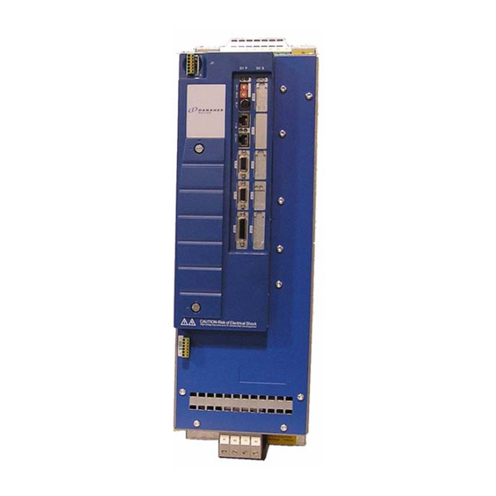
- Page 131 MMC Smart Drive Hardware Manual 460V 3 PHASE MMC SMART DRIVE NEXTGEN Figure 6-1: Front Panel, SDN Drives +24V CAUTION Risk of Electrical Shock High voltage may exist up to 5 minutes after removing power Kollmorgen - December 2011...
-
Page 132: Control Section Connectors, Switches, Leds
MMC Smart Drive Hardware Manual 460V 3 PHASE MMC SMART DRIVE NEXTGEN Control Section Connectors, Switches, LEDs This section describes the connectors, switches, and LEDs located on the Control Section (right portion) of the drive. 6.1.1 Status Display The Status Display is located on the top-front of the drive, and consists of two 7- segment displays. -
Page 133: Digital Link Ports
MMC Smart Drive Hardware Manual 460V 3 PHASE MMC SMART DRIVE NEXTGEN 6.1.3 Digital Link Ports The two 8-pin RJ-45 Digital Link Port connectors (labeled “IN” and “OUT” on the front of the Drive) provide communications between the Drive and other Digital Link devices (another Digital Drive, a Standalone MMC Digital Control, Slice I/O Coupler, DL-DIU, etc.). - Page 134 MMC Smart Drive Hardware Manual 460V 3 PHASE MMC SMART DRIVE NEXTGEN Table 6-2: Digital Link Port Pin Assignments Label In/Out Connector Pinout IN Connector Receive + Receive - Transmit + Not Used Not Used Transmit - Not Used RJ-45 Connectors...
-
Page 135: Feedback Connectors (F1 & F2)
MMC Smart Drive Hardware Manual 460V 3 PHASE MMC SMART DRIVE NEXTGEN Table 6-3: Digital Link Port “IN” to “OUT” Cables Part Numbers: .3 M (1.0 ft): M.1302.8285 .6 M (2.0 ft): M.1302.8286 1 M (3.3 ft): M.1302.8287 2 M (6.6 ft): M.1302.8288... - Page 136 MMC Smart Drive Hardware Manual 460V 3 PHASE MMC SMART DRIVE NEXTGEN Table 6-4: Pin Description for Feedback Connector (F1) F1 Feedback Signals Signal Type Signal Name Notes Incremental Encoder Differential A quad B encoder A1, A1/, B1, B1/, I1, I1/...
- Page 137 MMC Smart Drive Hardware Manual 460V 3 PHASE MMC SMART DRIVE NEXTGEN Table 6-5: Pin Assignments for Feedback Connector (F1) Feedback Device Sinewave Encoder Digital Hiper- Incremental Sine Connector Encoder face Endat BISS Wave SFD Resolver Pinout N/U (Not Used)
- Page 138 MMC Smart Drive Hardware Manual 460V 3 PHASE MMC SMART DRIVE NEXTGEN Table 6-6: Pin Description for Feedback Connector (F2) Signal Type Signal Name Notes Incremental Differential A quad B encoder A1, A1/, B1, Encoder In- signals. These can be defined...
- Page 139 MMC Smart Drive Hardware Manual 460V 3 PHASE MMC SMART DRIVE NEXTGEN Table 6-7: Pin Assignments for Feedback Connector (F2) Signal Name In/Out Connector Pinout I2 (Encoder) 15-pin Female In/Out Com+ (SFD HD D-Sub I2/ (Encoder) In/Out Com- (SFD Temperature+...
-
Page 140: Feedback Connectors (F1 And F2) Details
MMC Smart Drive Hardware Manual 460V 3 PHASE MMC SMART DRIVE NEXTGEN 6.1.4.1 Feedback Connectors (F1 and F2) Details The F1 and F2 Feedback connectors support a variety of devices and functions. This section helps clarify the capabilities and limitations of connected devices. - Page 141 MMC Smart Drive Hardware Manual 460V 3 PHASE MMC SMART DRIVE NEXTGEN Table 6-8: Supported Feedback Combinations Drive Feedback Configuration 1 and 4 (in PiCPro Drive Setup) F2 (Externally mounted F1 (Motor mounted feedback feedback device for position device for motor control)
- Page 142 MMC Smart Drive Hardware Manual 460V 3 PHASE MMC SMART DRIVE NEXTGEN Table 6-9: Feedback Port (F1 and F2) to Flying Lead Cable 1 M (3.3 ft): M.3000.1334 3 M (9.8 ft): M.3000.1335 6 M (19.7 ft): M.3000.1336 9 M (29.5 ft): M.3000.1337 Cable type: 28 AWG, (1 pair 16 AWG) shielded, twisted pair, 16 conductor.
- Page 143 MMC Smart Drive Hardware Manual 460V 3 PHASE MMC SMART DRIVE NEXTGEN Table 6-10: Feedback Ports (F1 and F2) Breakout Box and Cables Description Length Part Number M.1302.6970 Drive F1/F2 Port Breakout Board M.1302.6972 Drive F1/F2 Port Breakout Box 1 M (3.3 ft) M.3000.1330...
- Page 144 MMC Smart Drive Hardware Manual 460V 3 PHASE MMC SMART DRIVE NEXTGEN Figure 6-2: Feedback Port (F1 and F2) Breakout Box Dimensions Figure 6-3: Feedback Port (F1 and F2) Breakout Board Dimensions Kollmorgen - December 2011...
-
Page 145: Feedback Port (F1/F2) To Motor Cables
6.1.4.2 Feedback Port (F1/F2) to Motor Cables Cables are available that allow easy connection between the F1 & F2 Feedback Ports and various Kollmorgen motors. These cables are outlined in Table 6-11. The wiring diagram for each cable is located in the indicated Table. For information on Non-Flex versus Hi-Flex cables, refer to section 9.1 on page... - Page 146 MMC Smart Drive Hardware Manual 460V 3 PHASE MMC SMART DRIVE NEXTGEN Table 6-12: Feedback Port (F1/F2) Encoder to AKM/DDR Motor For Part Numbers, Table 6-11 on page 143 D-sub 15-Pin HD Male Connector to Motor Connector to MMC Smart...
- Page 147 MMC Smart Drive Hardware Manual 460V 3 PHASE MMC SMART DRIVE NEXTGEN Table 6-13: Feedback Port (F1) Endat/BiSS to AKM/DDR Motor For Part Numbers, Table 6-11 on page 143 D-sub 15-Pin HD Male Connector to Motor Connector to MMC Smart...
- Page 148 MMC Smart Drive Hardware Manual 460V 3 PHASE MMC SMART DRIVE NEXTGEN Table 6-14: Feedback Port (F1) Resolver to AKM/DDR Motor For Part Numbers, Table 6-11 on page 143 D-sub 15-Pin HD Male Connector to Motor Connector to MMC Smart...
- Page 149 MMC Smart Drive Hardware Manual 460V 3 PHASE MMC SMART DRIVE NEXTGEN Table 6-15: Feedback Port (F1/F2) SFD to AKM/DDR Motor For Part Numbers, Table 6-11 on page 143 D-sub 15-Pin HD Male Connector to Motor Connector to MMC Smart...
-
Page 150: Drive I/O Connectors (Io1 & Io2)
MMC Smart Drive Hardware Manual 460V 3 PHASE MMC SMART DRIVE NEXTGEN 6.1.5 Drive I/O Connectors (IO1 & IO2) The two 10-pin pluggable screw-terminal connectors (labeled “IO1” and "IO2" on the front of the Drive) provide connection between various devices and the Drive. These... - Page 151 MMC Smart Drive Hardware Manual 460V 3 PHASE MMC SMART DRIVE NEXTGEN Table 6-16: Pin Description for Drive I/O Connectors (IO1 & IO2) Signal Type Notes Pins Pins Analog Input Analog Input of -10VDC to +10VDC 1, 2 Analog Output...
- Page 152 MMC Smart Drive Hardware Manual 460V 3 PHASE MMC SMART DRIVE NEXTGEN Table 6-17: Pin Assignment for Drive I/O Connectors (IO1 & IO2) Connector IO2 Connector IO1 PiCPro PiCPro Wiring Connector Wiring Label Label In/Out Pin Label Label In/Out Pinout...
- Page 153 MMC Smart Drive Hardware Manual 460V 3 PHASE MMC SMART DRIVE NEXTGEN Figure 6-4: Wiring Diagram for Drive I/O Connectors (IO1 & IO2) Drive IO1-7 GPOUT 24 V 24 V Power From Supply Drive IO1-5 GPOUT1 Output From Device Drive...
-
Page 154: Power Section Connectors
MMC Smart Drive Hardware Manual 460V 3 PHASE MMC SMART DRIVE NEXTGEN Power Section Connectors This section describes the connectors located on the Power Section (left portion) of the drive. 6.2.1 DC Power Connector The DC Power Connector consists of a plugable 3-pin screw-terminal block, and provides +24VDC (nominal) Logic Power to the drive, as well as the "Safe Torque Off"... -
Page 155: Ac Power Connector
MMC Smart Drive Hardware Manual 460V 3 PHASE MMC SMART DRIVE NEXTGEN If during step 3 above, the user-supplied external circuitry removes 24Vdc from the "EN" input (usually due to a safety violation on the equipment being controlled), the drive will fault, and the motor will coast to a stop. The drive must be powered off and back on to remove the fault condition. -
Page 156: Motor/Brake Connector
MMC Smart Drive Hardware Manual 460V 3 PHASE MMC SMART DRIVE NEXTGEN Table 6-20: Recommended Fuses & Holders Combin- Fuse ation Fuse Part Holder Fuse Holder For Drive Model Fuse Number Type 3P Part Number MMC-SDN-1.8-460 DFJ6 M.3000.0190 30 Amp M.1016.1046... - Page 157 MMC Smart Drive Hardware Manual 460V 3 PHASE MMC SMART DRIVE NEXTGEN NOTE Use of a diode (as shown) or an external RC type snubber is highly recom- mended for use with inductive loads, especially DC inductive loads. Figure 6-5:...
-
Page 158: Motor/Brake Cables
Kollmorgen AKM/DDR motors. These cables are outlined in Table 6- 22. For a detailed description of these cables, refer to the Kollmorgen "AKD/S700 Accessories Manual" which can be found at www.kollmorgen.com. For information on Non-Flex versus Hi-Flex cables, refer to section 9.1 on page... -
Page 159: Dc Bus/Regen Connector
Available external regen resistors are outlined in Table 6-25. For a detailed description of these resistors, including mounting information, refer to the Kollmorgen "AKD/S700 Accessories Manual" which can be found at www.kollmorgen.com. Kollmorgen - December 2011... - Page 160 MMC Smart Drive Hardware Manual 460V 3 PHASE MMC SMART DRIVE NEXTGEN Table 6-25: External Regen Resistors Part For Drive Shunt Resistor Module Number 33Ω, 100W Cont. Power, 160W Peak Power BAFP-100-33 MMC-SDN-1.8- 33Ω, 200W Cont. Power, 320W Peak Power...
-
Page 161: Specifications - 460V Mmc Smart Drive Nextgen
MMC Smart Drive Hardware Manual 460V 3 PHASE MMC SMART DRIVE NEXTGEN Specifications - 460V MMC Smart Drive NextGen 6.3.1 General Data General Drive Data 3A & 6A Drives: 1.5mm (16 AWG), 75° C copper. Minimum wire size for AC PWR, RE- 12A Drive: 2.5mm... - Page 162 MMC Smart Drive Hardware Manual 460V 3 PHASE MMC SMART DRIVE NEXTGEN Conformity Conforms to Low Voltage Directive 73/23/EEC (amended by 93/68/EEC) and EMC Directive 89/336/EEC (amended by 92/31/EEC and 93/68/EEC). CE Marked (pending). Conformance is in accordance with the following stan-...
- Page 163 MMC Smart Drive Hardware Manual 460V 3 PHASE MMC SMART DRIVE NEXTGEN EN (Safe-off) Input Configuration 24Vdc (nominal) = Drive Enabled Guaranteed On 15 VDC Guaranteed Off 5 VDC Input Current, Typical 25mA. General Purpose Outputs • 2 optically isolated 24V DC outputs •...
- Page 164 MMC Smart Drive Hardware Manual 460V 3 PHASE MMC SMART DRIVE NEXTGEN General Purpose Analog Output -10VDC to +10VDC Output Characteristics 16 bit effective resolution Digital Link In/Out Ports Sends and receives high speed data to and from connect- “In” port ed MMC-SD’s “Out”...
-
Page 165: Physical And Electrical Data
MMC Smart Drive Hardware Manual 460V 3 PHASE MMC SMART DRIVE NEXTGEN 6.3.2 Physical and Electrical Data Model MMC- MMC- MMC- MMC- SDN- SDN-1.8- SDN-3.6- SDN-7.2- 14.4-460- 460-D 460-D 460-D Part Numbers M.3000.1300 M.3000.1301 M.3000.1302 M.3000.1303 Weight, lbs (kg) 6.0 (2.7) 6.0 (2.7) -
Page 166: Dimensions
MMC Smart Drive Hardware Manual 460V 3 PHASE MMC SMART DRIVE NEXTGEN Input = 400 VAC, 6.75 10.4 16.7 Input = 480 VAC, 12.5 Output Frequency, Hz 0-800 Energy Absorbtion Specifications DC Bus Capacitance 235 μF 470 μF 680 μF... - Page 167 MMC Smart Drive Hardware Manual 460V 3 PHASE MMC SMART DRIVE NEXTGEN Figure 6-6: 3, 6, and 12 Amp Drives - Front View 2.76 in (70 mm) .197 in .50 in (5 mm) (12.70 mm) .413 in (10.5 mm) .276 in (7 mm) 10.08 in...
- Page 168 MMC Smart Drive Hardware Manual 460V 3 PHASE MMC SMART DRIVE NEXTGEN Figure 6-7: 24 Amp Drive - Front 4.14 in (105 mm) .217 in .50 in (5.5 mm) (12.70 mm) .433 in (11 mm) .354 in (9 mm) 12.05 in 11.50 in...
-
Page 169: 3-Phase Mmc Smart Drive
MMC Smart Drive Hardware Manual 460V 3-PHASE MMC SMART DRIVE 460V 3-Phase MMC Smart Drive The 460V MMC Smart Drive is available in both analog and digital interfaced versions, with power ratings from 1.3kW through 65kW. This section describes these drives in detail. - Page 170 MMC Smart Drive Hardware Manual 460V 3-PHASE MMC SMART DRIVE Figure 7-1: Connectors on the Size 1 460V Smart Drive 24V Power Connector (J1) +24V Shunt/DC Bus +24V Connector Mains On Shunt On 24V Com 24V Com AC Input Power...
-
Page 171: Shunt/Dc Bus Connector
1D1 (ZK-) Note: A 4-pin screw-terminal mating connector is included with the drive. Additional connectors (P/N M.1302.7159) are available from Kollmorgen. NOTE The shunt resistor (if installed) across Ba+ and Ba- will be connected across the DC bus when the DC bus reaches the “shunt switch threshold” as shown in the specification table;... -
Page 172: Ac Power Connector
AC source Power must be center grounded Y sys- tem. Note: A 4-pin screw-terminal mating connector is included with the drive. Additional connectors (P/N M.1302.7158) are available from Kollmorgen. 7.2.1.3 Motor Connector Table 7-3: 460V Size 1 Motor Connector Signal Connector... -
Page 173: Power Connector (J1)
(due to improper wiring or 24 VDC supply failure), a fuse should be used in series with the 24 VDC to the MMC Smart Drive (4 A max). In addition, the 24 VDC shall be supplied by an isolating source such that the maximum open circuit voltage available to the MMC Smart Drive is not more than 30 VDC. -
Page 174: Motor Brake Connector (X101)
24 VDC com- Power 24VCOM Not Used. Used Note: A 6-pin cage-clamp mating connector is included with the drive. Additional connectors (P/N M.1302.7099) are available from Kollmorgen. Figure 7-2: Wiring Example for X101 Connector Drive Connector +24VBRK +24V BRAKE +... - Page 175 MMC Smart Drive Hardware Manual 460V 3-PHASE MMC SMART DRIVE Figure 7-3: Connectors on the Size 2 460V Drive 24V Power 460V Size 2 AC Power Connector Connector (J1) +24V +24V Mains On Shunt On 24V Com 24V Com Analog Interfaced...
-
Page 176: Ac Power Connector
MMC Smart Drive Hardware Manual 460V 3-PHASE MMC SMART DRIVE 7.2.2.1 AC Power Connector Table 7-6: 460V Size 2 AC Power Connector Connector Signal Type Signal Description Label In/Out Protective Ground Ground (Earth) Three phase AC input Power power in to drive... -
Page 177: Motor Connector
MMC Smart Drive Hardware Manual 460V 3-PHASE MMC SMART DRIVE 7.2.2.2 Motor Connector Table 7-7: 460V Size 2 Motor Connector Signal Connector Signal Type Description Label In/Out Connector Protective Ground Ground (Earth) Power U-phase from the drive to the motor... -
Page 178: Power Connector (J1)
(due to improper wiring or 24 VDC supply failure), a fuse should be used in series with the 24 VDC to the MMC Smart Drive. Spe- cifically, a 4 A max. “UL248 Series” fuse should be used. In addition, the 24 VDC shall be supplied by an isolating source such that the maximum open circuit voltage available to the MMC Smart Drive is not more than 30 VDC. -
Page 179: Size 3 Power Section Connectors
(supply and mag- 24VCOM net) Not Used. Used Note: A 6-pin cage-clamp mating connector is included with the drive. Additional connec- tors (P/N M.1302.7099) are available from Kollmorgen. Figure 7-4: Wiring Example for X101 Connector Drive Connector +24VBRK +24V BRAKE +... - Page 180 MMC Smart Drive Hardware Manual 460V 3-PHASE MMC SMART DRIVE Figure 7-5: Connectors on the Size 3 460V Drive Line Power Connector 24V Power Connector (J1) +24V +24V Mains On Shunt On 24V Com 24V Com Analog Interfaced Digital Interfaced...
-
Page 181: Ac Power Connector
MMC Smart Drive Hardware Manual 460V 3-PHASE MMC SMART DRIVE 7.2.3.1 AC Power Connector Table 7-10: 460V Size 3 AC Power Connector Connector Signal Type Signal Description Label In/Out Protective Ground Ground (Earth) Three phase AC input Power power in to drive... -
Page 182: Motor Connector
MMC Smart Drive Hardware Manual 460V 3-PHASE MMC SMART DRIVE 7.2.3.2 Motor Connector Table 7-11: 460V Size 3 Motor Connector Signal Signal Connector Type Description Label In/Out Connector Protective Ground Ground (Earth) Power U-phase from the drive to the motor... -
Page 183: Power Connector (J1)
(due to improper wiring or 24 VDC supply failure), a fuse should be used in series with the 24 VDC to the MMC Smart Drive. Spe- cifically, a 4 A max. “UL248 Series” fuse should be used. In addition, the 24 VDC shall be supplied by an isolating source such that the maximum open circuit voltage available to the MMC Smart Drive is not more than 30 VDC. -
Page 184: Motor Brake Connector (X101)
(supply and mag- 24VCOM net) Not Used. Used Note: A 6-pin cage-clamp mating connector is included with the drive. Additional connec- tors (P/N M.1302.7099) are available from Kollmorgen. Figure 7-6: Wiring Example for X101 Connector Drive Connector +24VBRK +24V BRAKE +... - Page 185 MMC Smart Drive Hardware Manual 460V 3-PHASE MMC SMART DRIVE Figure 7-7: Connectors on the Size 4 460V Drive Line Power Connector 24V Power Connector (J1) +24V +24V Mains On Shunt On 24V Com 24V Com Analog Interfaced Digital Interfaced...
-
Page 186: Ac Power Connector
MMC Smart Drive Hardware Manual 460V 3-PHASE MMC SMART DRIVE 7.2.4.1 AC Power Connector Table 7-14: 460V Size 4 AC Power Connector Connector Signal Type Signal Description Label In/Out Protective Ground Ground (Earth) Three phase AC input Power power in to drive... -
Page 187: Motor Connector
MMC Smart Drive Hardware Manual 460V 3-PHASE MMC SMART DRIVE 7.2.4.2 Motor Connector Table 7-15: 460V Size 4 Motor Connector Signal Signal Connector Type Description Label In/Out Connector Protective Ground Ground (Earth) Power U-phase from the drive to the motor... -
Page 188: Power Connector (J1)
(due to improper wiring or 24 VDC supply failure), a fuse should be used in series with the 24 VDC to the MMC Smart Drive. Spe- cifically, a 4 A max. “UL248 Series” fuse should be used. In addition, the 24 VDC shall be supplied by an isolating source such that the maximum open circuit voltage available to the MMC Smart Drive is not more than 30 VDC. -
Page 189: Motor Brake Connector (X101)
(supply and mag- 24VCOM net) Not Used. Used Note: A 6-pin cage-clamp mating connector is included with the drive. Additional connec- tors (P/N M.1302.7099) are available from Kollmorgen. Figure 7-8: Wiring Example for X101 Connector Drive Connector +24VBRK +24V BRAKE +... -
Page 190: Fan Connector (X36)
MMC Smart Drive Hardware Manual 460V 3-PHASE MMC SMART DRIVE 7.2.4.5 Fan Connector (X36) Table 7-18: 460V Size 4 Fan Connector (X36) Signal Signal Connector Type Description Label In/Out Connector 230VAC Line for Power 230VAC powering the fan 230VAC Neutral... -
Page 191: Typical 460V Drive Connection Layout
MMC Smart Drive Hardware Manual 460V 3-PHASE MMC SMART DRIVE Typical 460V Drive Connection Layout Optional Shunt Incoming AC Resistor Power (Mains) PE U V W +24V M24V X36-L 230VAC X36-N MMC-SD-460 X101-1 +24V X101-2 X101-3 X101-4 X101-5 X101-6 F1/F2... -
Page 192: Specifications - 460V Mmc Smart Drive)
MMC Smart Drive Hardware Manual 460V 3-PHASE MMC SMART DRIVE Specifications - 460V MMC Smart Drive) 7.4.1 Common Data for Size 1, 2, 3, 4 (All Models) General Drive Data Minimum wire size for input power 1.5mm2 (16 AWG) 75° C copper... - Page 193 MMC Smart Drive Hardware Manual 460V 3-PHASE MMC SMART DRIVE General Purpose Inputs • 8 optically isolated 24V DC inputs • Active high Configuration • 6 are current sourcing only (current flow into input) • 2 are sink or source...
- Page 194 MMC Smart Drive Hardware Manual 460V 3-PHASE MMC SMART DRIVE Drive I/O Connector Encoder Emulation Output Encoder Emulation Output F1 Motor Feedback Type Input Limit (A quad B Differential Output) The motor encoder A/B/I in- 720KHz puts are electrically buffered Incremental Encoder 2.88 M counts/sec.
-
Page 195: Physical/Electrical Data For 460V Size 1 Smart Drives
MMC Smart Drive Hardware Manual 460V 3-PHASE MMC SMART DRIVE 7.4.2 Physical/Electrical Data for 460V Size 1 Smart Drives Model MMC-SD-1.3-460 (-D) MMC-SD-2.4-460 (-D) Part Numbers Analog M.1302.5093 M.1302.5094 Digital, no BiSS M.1302.8133 M.1302.8134 Digital, BiSS M.3000.0464 M.3000.0465 Physical Weight 10 lbs. - Page 196 MMC Smart Drive Hardware Manual 460V 3-PHASE MMC SMART DRIVE DC Input Power Specifications (24VDC) Input Voltage Range 24VDC +15% -10% Typical Input Current 700mA Typical Input Wattage Inrush Current 4A for 10ms Internal Holding Brake Driver Maximum Current 0.5A...
-
Page 197: Physical/Electrical Data For 460V Size 2 Smart Drives
MMC Smart Drive Hardware Manual 460V 3-PHASE MMC SMART DRIVE 7.4.3 Physical/Electrical Data for 460V Size 2 Smart Drives Model MMC-SD-4.0-460 MMC-SD-6.0-460 MMC-SD-8.0-460 (-D) (-D) (-D) Part Numbers Analog M.1302.5095 M.1302.5096 M.1302.5097 Digital, no BiSS M.1302.8135 M.1302.8136 M.1302.8137 Digital, BiSS M.3000.0466... - Page 198 MMC Smart Drive Hardware Manual 460V 3-PHASE MMC SMART DRIVE AC Output Specifications Continuous Output Current RMS (0- 6.4A (9.0A) 9.6A (13.5A) 12.7A (18.0A) Peak) Continuous Output Power Input = 230 VAC 2.0kW 3.0kW 4.0kW Input = 460 VAC 4.0kW 6.0kW...
- Page 199 MMC Smart Drive Hardware Manual 460V 3-PHASE MMC SMART DRIVE External Shunt Maximum shunt 9A (AC) 9A (AC) 9A (AC) resistor current Minimum shunt 86Ω 60Ω 44Ω resistor Maximum shunt resistor power at 10kW 14kW minimum shunt resistor Kollmorgen - December 2011...
-
Page 200: Physical/Electrical Data For 460V Size 3 Smart Drives
MMC Smart Drive Hardware Manual 460V 3-PHASE MMC SMART DRIVE 7.4.4 Physical/Electrical Data for 460V Size 3 Smart Drives Model MMC-SD- MMC-SD- MMC-SD- MMC-SD- 12.0-460 16.0-460 24.0-460 30.0-460-D (-D) (-D) (-D) Part Numbers Analog M.1302.5098 M.1302.5099 M.1302.5100 M.3000.0545 Digital, no BiSS M.1302.8138... - Page 201 MMC Smart Drive Hardware Manual 460V 3-PHASE MMC SMART DRIVE AC Output Specifications Continuous Output 19.5A 25.8A 38.9A Current RMS (0- (49.0A (69.3A) (27.5A) (36.5A) (55.0A) Peak) Continuous Output Power Input = 230 VAC 6.0kW 8.0kW 12.0kW 15.0kW Input = 460 VAC 12.0kW...
- Page 202 MMC Smart Drive Hardware Manual 460V 3-PHASE MMC SMART DRIVE External Shunt Maximum shunt 36A (AC) 50A (AC) resistor current Minimum shunt 22Ω 16Ω resistor Maximum shunt resistor power at 29kW 40kW minimum shunt resistor Kollmorgen - December 2011...
-
Page 203: Physical/Electrical Data For 460V Size 4 Smart Drives
MMC Smart Drive Hardware Manual 460V 3-PHASE MMC SMART DRIVE 7.4.5 Physical/Electrical Data for 460V Size 4 Smart Drives Model MMC-SD- MMC-SD- MMC-SD- 42.0-460-D 51.0-460-D 65.0-460-D Part Numbers Analog M.3000.0546 M.3000.0547 M.3000.0548 Digital, BiSS M.3000.0022 M.3000.0023 M.3000.0024 Physical Weight 59 lbs. - Page 204 MMC Smart Drive Hardware Manual 460V 3-PHASE MMC SMART DRIVE AC Output Specifications Continuous Output 108.0A 66.0A (93.3A) 83.2A (117.4A) (152.7A) Current RMS (0-Peak) Continuous Output Power Input = 230 VAC 21.0kW 25.1kW 32.5kW Input = 460 VAC 42.0kW 51.0kW 65.0kW...
- Page 205 MMC Smart Drive Hardware Manual 460V 3-PHASE MMC SMART DRIVE External Shunt Maximum shunt 67A (AC) 100A (AC) 100A (AC) resistor current Minimum shunt 12Ω 8Ω resistor Maximum shunt resistor power at 53kW 80kW minimum shunt resistor Fan (X36 Connector)
-
Page 206: Dimensions For The 460V Smart Drives
MMC Smart Drive Hardware Manual 460V 3-PHASE MMC SMART DRIVE Dimensions for the 460V Smart Drives Figure 7-9: Size 1 460V Smart Drive - Front View Kollmorgen - December 2011... - Page 207 MMC Smart Drive Hardware Manual 460V 3-PHASE MMC SMART DRIVE Figure 7-10: Size 1 460V Smart Drive - Side View Kollmorgen - December 2011...
- Page 208 MMC Smart Drive Hardware Manual 460V 3-PHASE MMC SMART DRIVE Figure 7-11: Size 2 460V Smart Drive - Front View Kollmorgen - December 2011...
- Page 209 MMC Smart Drive Hardware Manual 460V 3-PHASE MMC SMART DRIVE Figure 7-12: Size 2 460V Smart Drive - Side View Kollmorgen - December 2011...
- Page 210 MMC Smart Drive Hardware Manual 460V 3-PHASE MMC SMART DRIVE Figure 7-13: Size 3 460V Smart Drive - Front View Kollmorgen - December 2011...
- Page 211 MMC Smart Drive Hardware Manual 460V 3-PHASE MMC SMART DRIVE Figure 7-14: Size 3 460V Smart Drive - Side View Kollmorgen - December 2011...
- Page 212 MMC Smart Drive Hardware Manual 460V 3-PHASE MMC SMART DRIVE Figure 7-15: Size 4 460V Smart Drive - Front View 4.72in. 1.38in. (120.00mm) (35.00mm) 25.88in. (655.00mm) 7.5in. (190.00mm) Kollmorgen - December 2011...
- Page 213 MMC Smart Drive Hardware Manual 460V 3-PHASE MMC SMART DRIVE Figure 7-16: Size 4 460V Smart Drive - Side View 26.18in. (665.00mm) 12.71in. (322.63mm) Kollmorgen - December 2011...
- Page 214 MMC Smart Drive Hardware Manual 460V 3-PHASE MMC SMART DRIVE Kollmorgen - December 2011...
-
Page 215: S200-Dls Drive
S200-DLS DRIVE S200-DLS Drive This chapter only pertains to the S200-DLS Drive, not to the MMC Smart Drive. The S200-DLS consists of a Base Unit with an S200 Digital Link Option Card installed. The combination of the two components is the S200-DLS Drive. The Base Unit is described in detail in Kollmorgen’s S200 Base Unit Reference Manual, P/N M-SM-... - Page 216 MMC Smart Drive Hardware Manual S200-DLS DRIVE Figure 8-1: STATUS S200-DLS SERIES Kollmorgen - December 2011...
-
Page 217: S200-Dls Option Card
MMC Smart Drive Hardware Manual S200-DLS DRIVE S200-DLS Option Card The S200 Option Card is located on the right side of the S200-DLS Drive. This section explains in detail the various indicators and connectors located on the S200 Option Card. -
Page 218: Node Address Rotary Switches
MMC Smart Drive Hardware Manual S200-DLS DRIVE 8.1.4 Node Address Rotary Switches Two rotary switches are used to set the drive address. Rotate the switch to the desired address. Addresses can be set to any number from 1 through 64. The top switch represents values of base ten. -
Page 219: Digital Link Ports
DLS and: another S200-DLS Drive • a Digital Link Accessory (DL-DIU, Slice I/O Coupler, etc.) • an MMC Smart Drive (including a Drive that contains a Drive Resident MMC Con- • trol) • an MMC-DSA Control (MMC-DSA2, -DSA4, -DSA8, -DSA16) •... - Page 220 MMC Smart Drive Hardware Manual S200-DLS DRIVE Table 8-3: Digital Link Port Pin Assignments Label In/Out Connector Pinout IN Connector Receive + Receive - Transmit + Not Used Not Used Transmit - Not Used RJ-45 Connectors Not Used Provides a path for the...
-
Page 221: Auxiliary Feedback Port
MMC Smart Drive Hardware Manual S200-DLS DRIVE Table 8-4: Digital Link Port “IN” to “OUT” Cables Part Numbers: .3 M (1.0 ft): M.1302.8285 .6 M (2.0 ft): M.1302.8286 1 M (3.3 ft): M.1302.8287 2 M (6.6 ft): M.1302.8288 3 M (9.8 ft): M.1302.8289... - Page 222 MMC Smart Drive Hardware Manual S200-DLS DRIVE Table 8-5: Aux Feedback Port Pin Description Aux Feedback Signals Signal Type Signal Name Notes Incremental Encoder In- Differential A quad B encoder A1, A1/, B1, B1/, I1, I1/ 1, 2, 3, 4, 5, 10 puts signals.
- Page 223 MMC Smart Drive Hardware Manual S200-DLS DRIVE Table 8-6: Aux Feedback Port Pin Assignments Encoder Pin Assignments for Aux Feedback 15 Pin Connector Feedback Device Endat Digital BISS Incremental Connector Encoder In/Out Pinout RS-485 Data+ Note 15-pin Female Common In/Out...
- Page 224 MMC Smart Drive Hardware Manual S200-DLS DRIVE Table 8-7: Aux Feedback Port to Flying Lead Cable Part Numbers: 1 M (3.3 ft): M.3000.0805 3 M (9.8 ft): M.3000.0806 6 M (19.7 ft): M.3000.0807 9 M (19.5 ft): M.3000.0808 Cable type: 28 AWG (pins 6 & 14 16 AWG), shielded, twisted pair, 16 conductor.
- Page 225 MMC Smart Drive Hardware Manual S200-DLS DRIVE Table 8-8: Aux Feedback Port Breakout Box and Cables Description Length Part Number M.1302.6970 Aux Feedback Port Breakout Board M.1302.6972 Aux Feedback Port Breakout Box 1 M (3.3 ft) M.3000.0801 3 M (9.8 ft) M.3000.0802...
- Page 226 MMC Smart Drive Hardware Manual S200-DLS DRIVE Figure 8-3: Aux Feedback Port Breakout Box Dimensions Figure 8-4: Aux Feedback Port Breakout Board Dimensions Kollmorgen - December 2011...
- Page 227 MMC Smart Drive Hardware Manual S200-DLS DRIVE Table 8-9: Aux Feedback Port ENDAT/BiSS to AKM/DDR Motor Cable Part Numbers: 1 M (3.3 ft): M.1302.0809 3 M (9.8 ft): M.1302.0810 6 M (19.7 ft): M.1302.0811 9 M (29.5 ft): M.1302.0812 15 M (49.2 ft): M.1302.0813 30 M (98.4 ft): M.1302.0814...
- Page 228 MMC Smart Drive Hardware Manual S200-DLS DRIVE Table 8-10: Aux Feedback Port Encoder to AKM/DDR Motor Part Numbers: 1 M (3.3 ft): M.3000.1285 3 M (9.8 ft): M.3000.1286 6 M (19.7 ft): M.3000.1287 9 M (29.5 ft): M.3000.1288 15 M (49.2 ft): M.3000.1289 30 M (98.4 ft): M.3000.1290...
-
Page 229: Drive I/O And I/O Power Ports
MMC Smart Drive Hardware Manual S200-DLS DRIVE 8.1.7 Drive I/O and I/O Power Ports The 8-pin plugable spring-terminal Drive I/O Port connector (labeled "J7 DRIVE I/O" on the front of the Drive) in combination with the 6-pin plugable spring-terminal I/O Power Port connector (labeled "J6 I/O POWER"... - Page 230 MMC Smart Drive Hardware Manual S200-DLS DRIVE Table 8-12: Drive I/O Port Pin Assignments Signal In/Out Connector Pinout DC Input 8 DC Input 7 (Data Capture input for 8-Pin plugable Screw J8 Aux Feedback connector) Terminal Connector DC Input 6...
-
Page 231: Drive I/O Port Details
MMC Smart Drive Hardware Manual S200-DLS DRIVE Table 8-13: I/O Power Port Pin Descriptions Function Notes I/O 24V Power Nominal 24 Vdc to power Drive I/O I/O 24V Common I/O 24V common This pin determines whether Drive I/O inputs 5 DC Inputs 5 and 6 &... -
Page 232: Drive I/O Port Outputs
MMC Smart Drive Hardware Manual S200-DLS DRIVE 8.1.8.1 Drive I/O Port Outputs The Drive I/O Port provides 4 source-only 24 Vdc outputs. For sourcing outputs, one side of the load is connected to the Output pin on the Drive I/O connector, and the other side of the load is connected to 24 Vdc Common. -
Page 233: Power Section Wiring Accessories
MMC Smart Drive Hardware Manual S200-DLS DRIVE Figure 8-5: Connecting Devices to the Drive I/O Port Drive I/O Port LOADS DCOUT1 DCOUT2 DCOUT3 DRIVE I/O DCOUT4 DCIN5 SINKING DCIN6 DCIN7 SOURCING DCIN8 5&6 SS 7&8 SS 24VDCIN I/O PWR 24VDC COM... - Page 234 MMC Smart Drive Hardware Manual S200-DLS DRIVE Table 8-16: Power Section Wiring Accessories Description Part Number Command I/O (J4) Drive-mounted Breakout Board M.1302.6971 Command I/O (J4) Panel-mounted Breakout Box M.1302.6973 Command I/O (J4) to Breakout Box cables: 3.3ft (1M) M.1302.6982 9.8ft (3M)
-
Page 235: Specifications - S200-Dls Drive
The S200-DLS consists of a Base Unit with an S200 Digital Link Option Card installed. The combination of the two components is the S200-DLS Drive. The Base Unit is described in detail in Kollmorgen’s S200 Base Unit Reverence Manual, P/N M-SM- 200-01, which can be found at http://www.kollmorgen.com/website/com/eng/products/... - Page 236 MMC Smart Drive Hardware Manual S200-DLS DRIVE Drive I/O Port DC Outputs • 4 optically isolated 24V DC outputs • Active high Configuration • Current sourcing only (current into load) • Short circuit and overload protected Maximum current 50mA per output...
-
Page 237: Motor Cables & Connectors
MMC Smart Drive Hardware Manual MOTOR CABLES & CONNECTORS Motor Cables & Connectors Kollmorgen offers many cables that connect directly from the MMC Smart Drive’s F1/ F2 connector to various Kollmorgen motors. These cables are described in detail in section 5.1.6.2 on page... -
Page 238: Cable Tension
MMC Smart Drive Hardware Manual MOTOR CABLES & CONNECTORS Doubling the minimum bending radius for reeling applications can triple cable life at the maximum recommended tension. Therefore, the largest possible bending radius should be used to increase cable life. 9.1.2 Cable Tension Cable tension plays an extremely important role in determining cable life in reeling. - Page 239 MMC Smart Drive Hardware Manual MOTOR CABLES & CONNECTORS • The cable must be able to move freely in the track The cable must be able to move in the radius section of the track. This must be • checked in the track’s fully extended position.
-
Page 240: Akm/Ddr Motor Power Cables
MMC Smart Drive Hardware Manual MOTOR CABLES & CONNECTORS AKM/DDR Motor Power Cables This section describes flying-lead wiring assemblies that can be used connect the Motor power signals from the drive to an AKM/DDR motor. Each assembly consists of the proper motor connector, and the indicated length and gauge of Hi-Flex cable. -
Page 241: Lsm/Msm Motor Connector Kits
MMC Smart Drive Hardware Manual MOTOR CABLES & CONNECTORS LSM/MSM Motor Connector Kits This section describes LSM/MSM Motor mating connectors for use in constructing custom cables using user-supplied cable. Available connectors are described in Table 9-3. Table 9-3: Connector Kits for LSM/MSM Motors... -
Page 242: Lsm/Msm Motor Power Cables
MMC Smart Drive Hardware Manual MOTOR CABLES & CONNECTORS LSM/MSM Motor Power Cables This section describes flying-lead wiring assemblies that can be used connect the Motor Power signals from the drive to an LSM/MSM motor. Each assembly consists of the indicated length and gauge of Hi-Flex cable pre-wired to the indicated LSM/ MSM Motor power connector. - Page 243 MMC Smart Drive Hardware Manual MOTOR CABLES & CONNECTORS 1 M (3.3 ft) M.1302.1146 3 M (9.8 ft) M.1302.1147 Size 1.5.2 in 8AWG Table 9-5 on 6 M (19.7 ft) M.1302.1148 page 242 9 M (29.5 ft) M.1302.1149 15 M (49.2 ft) M.1302.1150...
- Page 244 MMC Smart Drive Hardware Manual MOTOR CABLES & CONNECTORS Table 9-5: LSM/MSM Motor Power Connector Flying Lead Cables Connector Pinout Size 1.5.1 Size 1.5.2 Wire Wire Signal Size 1 Power Power Power Color Number Type Connector Connector Connector Black (1)
-
Page 245: Lsm/Msm Motor Fan Cables
MMC Smart Drive Hardware Manual MOTOR CABLES & CONNECTORS LSM/MSM Motor Fan Cables This section describes flying-lead wiring assemblies that can be used connect the Motor Fan signals from the drive to an LSM/MSM motor. Each assembly consists of the indicated length of 16AWG cable pre-wired to the LSM/MSM Motor fan connector. - Page 246 MMC Smart Drive Hardware Manual MOTOR CABLES & CONNECTORS Kollmorgen - December 2011...
-
Page 247: Maintenance And Troubleshooting
MMC Smart Drive Hardware Manual MAINTENANCE AND TROUBLESHOOTING Maintenance and Troubleshooting 10.1 Maintenance WARNING Disconnect input power before touching cables or connections. DC bus capacitors may retain hazardous voltages af- ter input power has been removed. Before working on the drive, measure the DC bus voltage to verify it has reached a safe level. -
Page 248: Troubleshooting
MMC Smart Drive Hardware Manual MAINTENANCE AND TROUBLESHOOTING 10.2 Troubleshooting 10.2.1 General Troubleshooting Refer to Table 10-1 for general troubleshooting information. Table 10-1: General Troubleshooting Symptoms, Causes, Remedies Symptom Possible Cause Remedy Verify 24 VDC power is applied No 24VDC input power. -
Page 249: Troubleshooting With The Diagnostic Led (D1)
MMC Smart Drive Hardware Manual MAINTENANCE AND TROUBLESHOOTING • The 230V smart Drive, 460V Smart Drive, and S200-DLS contain a Diagnostic LED (D1) that is located on the front of the Drive. This Diagnostic LED is covered in detail in section 10.2.4.1 on page... - Page 250 MMC Smart Drive Hardware Manual MAINTENANCE AND TROUBLESHOOTING Fault conditions give the user an indication of a more serious problem, and disable the Drive. Whenever a Fault condition is detected, the drive generates a two-digit Fault Code. The Drive Diagnostic Codes are described in Table 10-2.
- Page 251 MMC Smart Drive Hardware Manual MAINTENANCE AND TROUBLESHOOTING Table 10-2: Drive Diagnostic LED Codes Code Description Possible Causes Possible Remedies Codes 01 through 06 are Warning Codes, and do not disable the Drive Drive Heatsink Drive heatsink tempera- Temp. Warning ture exceeds warning limit •...
- Page 252 MMC Smart Drive Hardware Manual MAINTENANCE AND TROUBLESHOOTING Table 10-2: Drive Diagnostic LED Codes (Continued) Code Description Possible Causes Possible Remedies Change the deceleration or mo- Excessive regeneration of tion profile. power. Check shunt connections and The motor may regener-...
- Page 253 MMC Smart Drive Hardware Manual MAINTENANCE AND TROUBLESHOOTING Table 10-2: Drive Diagnostic LED Codes (Continued) Code Description Possible Causes Possible Remedies Verify ambient temperature is Drive current and voltage not too high. output, in combination Operate within the continuous with the heatsink temper- power rating.
- Page 254 MMC Smart Drive Hardware Manual MAINTENANCE AND TROUBLESHOOTING Table 10-2: Drive Diagnostic LED Codes (Continued) Code Description Possible Causes Possible Remedies Operate within (not above) the Drive ambient tempera- continuous rating for the ambient Drive Ambient ture exceeds the drive temperature.
- Page 255 MMC Smart Drive Hardware Manual MAINTENANCE AND TROUBLESHOOTING Table 10-2: Drive Diagnostic LED Codes (Continued) Code Description Possible Causes Possible Remedies Verify AC power is applied to Drive Power Mod- The drive’s power section drive. ule Fault detects a fault condition.
- Page 256 MMC Smart Drive Hardware Manual MAINTENANCE AND TROUBLESHOOTING Table 10-2: Drive Diagnostic LED Codes (Continued) Code Description Possible Causes Possible Remedies Overtravel Plus Fault status can be monitored using READ_SV variable 68 AND (16#400 0000). Fault input write a 0 to WRITE_SV variable 86.
-
Page 257: Troubleshooting Using The Status Led (Status)
MMC Smart Drive Hardware Manual MAINTENANCE AND TROUBLESHOOTING Table 10-2: Drive Diagnostic LED Codes (Continued) Code Description Possible Causes Possible Remedies Power applied to an unini- Initialize and configure the drive Drive Not Ready tialized drive. using PiCPro. 10.2.4.3 Troubleshooting using the Status LED (STATUS) This section pertains to the Status LED labeled "STATUS"... - Page 258 MMC Smart Drive Hardware Manual MAINTENANCE AND TROUBLESHOOTING Table 10-3: Drive Status LED Fault Codes (Continued) Fault Fault Possible Causes Code Drive I*t Too High Mechanically-jammed motor. • The product of the drives • • Motion profile acceleration requires output current multiplied...
- Page 259 MMC Smart Drive Hardware Manual MAINTENANCE AND TROUBLESHOOTING Table 10-3: Drive Status LED Fault Codes (Continued) Fault Fault Possible Causes Code • Insufficient motor inductance Output Over Current KIP or KII improperly set causing • excessive output current overshoots. Hall Fault •...
- Page 260 MMC Smart Drive Hardware Manual MAINTENANCE AND TROUBLESHOOTING Table 10-3: Drive Status LED Fault Codes (Continued) Fault Fault Possible Causes Code Position Error Too Large • If ExtFaults = Step size over flow then GearOut/GearIn is too large. • If ExtFaults = Position error over flow then the following error (PosErr), has exceeded ±128 revs.
-
Page 261: Resolver Interface Option Module
460V drive, turn the 2 locking screws on the front of the drive clock- wise and remove the MMC Smart Drive board from the drive chassis. 2. Remove the shunt from the 24-pin DIP socket located on the MMC Smart Drive board (See Figure 11-1 on page 260). - Page 262 1. If the Resolver Module was installed in a 460V drive, re-install the MMC Smart Drive board into the chassis and turn the 2 locking screws on the front of the drive counter-clockwise to secure the front panel to the chassis.
- Page 263 MMC Smart Drive Hardware Manual RESOLVER INTERFACE OPTION MODULE Figure 11-2: : Shunt Removed and Resolver Module Installed Connector side of Board 230V MMC Smart Drive Board Resolver Resolver Module 460V MMC Smart Module Drive Board View A View A...
- Page 264 MMC Smart Drive Hardware Manual RESOLVER INTERFACE OPTION MODULE 11.3 Specifications Resolver Interface Option Module Characteristics Specifications Part Number M.1302.4523 Function Resolver to encoder converter Field Side Connector F1 Feedback Connector Excitation Frequency 5 kHz Output Voltage Current per Output Channel, 28 mA max.
-
Page 265: Drive Resident Digital Mmc Control
Digital MMC- D16 (controls 16 MMC-SD-D) PiCPro is used to program the Drive Resident Digital MMC Control. The built-in I/O (eight 24VDC inputs and eight 24VDC outputs) can be expanded using Kollmorgen serially distributed block I/O (not included on the Digital MMC-D1). - Page 266 MMC Smart Drive Hardware Manual DRIVE RESIDENT DIGITAL MMC CONTROL Figure 12-1: The Drive Resident Digital MMC Control Scan LED (S) Diagnostic LED (D2) (Green) (Yellow) Block I/O Port (C1)* (9-Pin Standard D-Shell) User Serial Port (C3) (15-Pin High Density D-Shell)
-
Page 267: Installing The Drive Resident Digital Mmc Control
MMC Smart Drive Hardware Manual DRIVE RESIDENT DIGITAL MMC CONTROL 12.2 Installing the Drive Resident Digital MMC Control 12.2.1 Installing into a 230V MMC-SD Drive Remove the three screws from the right side of the cover and one screw from the top and bottom of the drive near the front. -
Page 268: System Wiring Guidelines
MMC Smart Drive Hardware Manual DRIVE RESIDENT DIGITAL MMC CONTROL drive until the 20-pin connector is completely seated and the Drive Resident Digi- tal MMC Control is seated against the threaded standoffs installed in step 5. 10. Tighten the 5 screws loosened in step 7 11. -
Page 269: Starting An Operation
MMC Smart Drive Hardware Manual DRIVE RESIDENT DIGITAL MMC CONTROL Low level signals that can be less than three meters in length or can be separated from noise sources are tested at a 1 KV level. Under the stated conditions, there will be no disturbance of digital I/O, encoder, or encoder operation. -
Page 270: Start-Up Diagnostics
MMC Smart Drive Hardware Manual DRIVE RESIDENT DIGITAL MMC CONTROL Table 12-1: Troubleshooting Summary In order to: Do the following: Turn off main disconnect (which should also turn off all external power supplies to Turn off the entire application. the application); unplug the DC power to the MMC-SD. -
Page 271: Drive Resident Digital Mmc Control Start-Up Diagnostic Leds
MMC Smart Drive Hardware Manual DRIVE RESIDENT DIGITAL MMC CONTROL 12.4.3.3 Drive Resident Digital MMC Control Start-Up Diagnostic LEDs The LED D2 light on the Drive Resident Digital MMC Control lights up briefly while its diagnostic tests are running and then goes off. If D2 remains on, the Drive Resident Digital MMC Control has failed one of its tests. -
Page 272: Mmc Run-Time Diagnostics
MMC Smart Drive Hardware Manual DRIVE RESIDENT DIGITAL MMC CONTROL 12.4.4 MMC Run-Time Diagnostics While the Drive Resident Digital MMC Control is running, other tests are performed on a regular basis with their results also reported by D2. While the Drive Resident Digital MMC Control is running, the D2 will flash a three digit code signal if there is an error. -
Page 273: Connectors & Operation
DRIVE RESIDENT DIGITAL MMC CONTROL 12.5 Connectors & Operation Kollmorgen provides many optional accessories that simplify wiring the Drive Resident Digital MMC Control to external devices. These accessories include cables to connect MMC-SD drives together and breakout boxes that provide screw-terminal connections to the Drive Resident Digital MMC Control. - Page 274 MMC Smart Drive Hardware Manual DRIVE RESIDENT DIGITAL MMC CONTROL Table 12-3: Block I/O Port Pin Descriptions Function Notes Transmit Data + Transmits data to Block I/O Modules. Transmit Data - Transmits data to Block I/O Modules. Receive Data + Receives data from Block I/O Modules.
- Page 275 MMC Smart Drive Hardware Manual DRIVE RESIDENT DIGITAL MMC CONTROL Table 12-5: Block I/O Port to Flying Lead Cable Part Number: M.1016.2568 Length: 3 M (10 ft) Cable type: 24 AWG, twisted pair (individually shielded), 4 conductor. 9-Pin male D-sub (to Block I/O Port, face view)
- Page 276 MMC Smart Drive Hardware Manual DRIVE RESIDENT DIGITAL MMC CONTROL Table 12-6: Block I/O Port to Block I/O Module Wiring Use this table to wire from the Block I/O Port to the first Block I/O Module. 9-Pin male D-sub (to Block I/O...
-
Page 277: User Port
MMC Smart Drive Hardware Manual DRIVE RESIDENT DIGITAL MMC CONTROL Figure 12-3: Block I/O Breakout Box Dimensions 1.750” 3.000” 1.750” 2.250” 12.5.3 User Port The 15-pin HD male D-sub User Port connector (labeled “C3” on the front of the Control) provides RS232 and RS485 serial communication between a serial device and the Control. - Page 278 MMC Smart Drive Hardware Manual DRIVE RESIDENT DIGITAL MMC CONTROL Table 12-8: User Port Pin Descriptions Function Notes RS232-level signal that receives serial data RS232 Receive Data from the connected serial device. RS232-level signal that sends serial data to RS232 Transmit Data the connected serial device.
- Page 279 MMC Smart Drive Hardware Manual DRIVE RESIDENT DIGITAL MMC CONTROL Table 12-9: User Port Pin Assignments Signal In/Out Connector Pinout RS232 Data-terminal-ready (12 Vdc) 15-pin HD male D-sub RS232 Request-to-Send RS232 Clear- to-Send Signal Ground In/Out RS232 Receive Data RS232 Transmit Data...
- Page 280 MMC Smart Drive Hardware Manual DRIVE RESIDENT DIGITAL MMC CONTROL Table 12-10: User Port to Flying Lead Cable Part Number: M.1016.2565 Length: 3 M (10 ft) Cable type: 28 AWG, shielded, twisted pair, 16 conductor. 15-Pin HD female D-sub (to User Port, face view)
- Page 281 MMC Smart Drive Hardware Manual DRIVE RESIDENT DIGITAL MMC CONTROL Table 12-11: User Port to RS-232 Exter HMI Cable Part Number: M.1302.8453 Length: 4 M (13 ft) Cable type: 24 AWG, shielded, twisted pair, 4 conductor. 9-Pin female D-sub (to...
- Page 282 MMC Smart Drive Hardware Manual DRIVE RESIDENT DIGITAL MMC CONTROL Table 12-12: User Port to RS-485 Exter HMI Cable Part Number: M.1302.8454 Length: 4 M (13 ft) Cable type: 24 AWG, shielded, twisted pair, 6 conductor. 25-Pin male D-sub (to...
-
Page 283: Ethernet Port
MMC Smart Drive Hardware Manual DRIVE RESIDENT DIGITAL MMC CONTROL Figure 12-4: User Port Breakout Box Dimensions 1.750” 3.000” 2.250” 2.250” 12.5.4 Ethernet Port The 8-pin RJ-45 Ethernet Port connector (labeled “C4” on the front of the Control) provides IEEE 802.3/802.3u-100Base-TX/10Base T, half duplex connectivity between an Ethernet device and the Control. - Page 284 MMC Smart Drive Hardware Manual DRIVE RESIDENT DIGITAL MMC CONTROL Table 12-14: Ethernet Port Pin Descriptions Function Notes Provides a path for shield current through the Shield Ground Shell chassis to an external single point ground. Table 12-15: Ethernet Port Pin Assignments...
-
Page 285: General I/O Port (C5)
MMC Smart Drive Hardware Manual DRIVE RESIDENT DIGITAL MMC CONTROL Table 12-16: Ethernet Port to Ethernet Device Cables Part Numbers: .3 M (1.0 ft): M.1302.8285 .6 M (2.0 ft): M.1302.8286 1 M (3.3 ft): M.1302.8287 2 M (6.6 ft): M.1302.8288 3 M (9.8 ft):... - Page 286 MMC Smart Drive Hardware Manual DRIVE RESIDENT DIGITAL MMC CONTROL Table 12-17: General I/O Port Pin Descriptions Function Notes Nominal 24 Vdc Outputs capable of sourcing DC Outputs 1-8 up to 250 ma. DC Inputs 1-8 Nominal 24 Vdc sourcing Inputs...
- Page 287 MMC Smart Drive Hardware Manual DRIVE RESIDENT DIGITAL MMC CONTROL Table 12-18: General I/O Port Pin Assignments Signal In/Out Connector Pinout DCOUT1 DCOUT2 DCOUT3 DCOUT4 DCOUT5 DCOUT6 26-pin HD male D-sub DCOUT7 DCOUT8 24VDCIN 10-13 IO24V In/Out 14-18 IO24C In/Out...
- Page 288 MMC Smart Drive Hardware Manual DRIVE RESIDENT DIGITAL MMC CONTROL Table 12-19: General I/O Port to Flying Lead Cable Part Numbers: 1 M (3.3 ft): M.1302.8257 15 M (49.2 ft): M.1302.8290 3 M (10 ft): M.1302.8258 30 M (98.4 ft): M.1302.8291...
- Page 289 MMC Smart Drive Hardware Manual DRIVE RESIDENT DIGITAL MMC CONTROL Table 12-20: General I/O Port Breakout Box and Cables Description Length Part Number M.1302.8480 DR Control Gen I/O Breakout Board M.1302.8253 DR Control Gen I/O Breakout Box 1 M (3.3 ft) M.1302.8254...
-
Page 290: Dc Output Operation
MMC Smart Drive Hardware Manual DRIVE RESIDENT DIGITAL MMC CONTROL Figure 12-6: General I/O Port Breakout Board Dimensions 12.5.5.1 DC Output Operation The General I/O Port provides 8 source-only 24 Vdc outputs. These outputs get their power from Pin 9 of the General I/O connector. Each of the 8 outputs on the general I/ O connector is a solid state switch rated at 250 ma. - Page 291 MMC Smart Drive Hardware Manual DRIVE RESIDENT DIGITAL MMC CONTROL Figure 12-7: Connecting Output Devices to the General I/O Port (C5) Drive Resident Digital MMC Control GENERAL CONNECTOR DC OUTPUT PINS LOAD IO24C DCOUT1 DCOUT2 DCOUT3 DCOUT4 DCOUT5 DCOUT6 DCOUT7...
-
Page 292: Dc Input Operation
MMC Smart Drive Hardware Manual DRIVE RESIDENT DIGITAL MMC CONTROL 12.5.5.2 DC Input Operation The General I/O Port provides eight 24 Vdc sourcing inputs. An example of connecting the DC Inputs to the Control is shown in Figure 12-8. Kollmorgen - December 2011... - Page 293 MMC Smart Drive Hardware Manual DRIVE RESIDENT DIGITAL MMC CONTROL Figure 12-8: Connecting Input Devices to the General I/O Port (C5) Drive Resident Digital MMC Control GENERAL CONNECTOR DC INPUT PINS I/O 24C +24V DCIN1 DCIN2 SOURCE DCIN3 DCIN4 DCIN5...
-
Page 294: Specifications
.0167 a. Using features such as servo tasks, S-curve, RATIO_RL, M_LINCIR, M_SCRVLC, PLS, and CAM_OUT places a heavier burden on available CPU time. Consult Kollmorgen for assistance if you want to exceed the number of axes in this chart. 32 bit RISC processor with numeric coprocessor... - Page 295 MMC Smart Drive Hardware Manual DRIVE RESIDENT DIGITAL MMC CONTROL Input voltage from MMC-SD Drive 20 VDC to 30 VDC Input power from MMC-SD Drive 250 mA Access via PiCPro 10.2 and above or your application pro- Time-of-day clock gram At 25°C (77°F),±1 second per day...
- Page 296 MMC Smart Drive Hardware Manual DRIVE RESIDENT DIGITAL MMC CONTROL Kollmorgen - December 2011...
-
Page 297: Declarations Of Conformity
MMC Smart Drive Hardware Manual DECLARATIONS OF CONFORMITY Declarations of Conformity Kollmorgen - December 2011... - Page 298 MMC Smart Drive Hardware Manual DECLARATIONS OF CONFORMITY Kollmorgen - December 2011...
- Page 299 MMC Smart Drive Hardware Manual DECLARATIONS OF CONFORMITY Kollmorgen - December 2011...
- Page 300 MMC Smart Drive Hardware Manual DECLARATIONS OF CONFORMITY Kollmorgen - December 2011...
- Page 301 MMC Smart Drive Hardware Manual DECLARATIONS OF CONFORMITY Kollmorgen - December 2011...
- Page 302 MMC Smart Drive Hardware Manual DECLARATIONS OF CONFORMITY Kollmorgen - December 2011...
-
Page 303: A 460V Mmc Smart Drive Dc Bus Sharing
MMC Smart Drive Hardware Manual 460V MMC SMART DRIVE DC BUS SHARING Appendix A- 460V MMC Smart Drive DC Bus Sharing Introduction This section discusses DC bus sharing among 2 or more 460V Smart Drives. DC bus sharing accomplishes 4 things: •... - Page 304 MMC Smart Drive Hardware Manual 460V MMC SMART DRIVE DC BUS SHARING Figure A-1: DC Bus Sharing with AC Input Power to All Drives Incoming AC Power to AC Power Next Drive (Mains) if Applicable Circuit Protection Devices Circuit Protection Devices...
-
Page 305: Dc Bus Sharing With Ac Power To One Drive
The system will have the combined DC Bus capacitance of all drives connected. Ταβλε Α−2 ον παγε 306 shows the MMC Smart Drive bus capacitance and energy absorption capability. Kollmorgen - December 2011... - Page 306 MMC Smart Drive Hardware Manual 460V MMC SMART DRIVE DC BUS SHARING Table A-1: kW Ratings for Powered Drive Bus power available for Continuous Peak linking to other Current Current Drive Model drives (Amps) (Amps) MMC-SD-1.3-460 2.0kW MMC-SD-2.4-460 2.0kW MMC-SD-4.0-460 5.0kW...
- Page 307 MMC Smart Drive Hardware Manual 460V MMC SMART DRIVE DC BUS SHARING Figure A-2: Two or more drives with AC input power to one drive Incoming AC Power (Mains) Circuit Protection Devices (Supply Circuit Disconnect, SCPD, Line Filter etc..) Line Reactor...
- Page 308 MMC Smart Drive Hardware Manual 460V MMC SMART DRIVE DC BUS SHARING Table A-2: Drive Bus Capacitance and energy Absorption Capability Energy Energy Energy Smart Absorption Absorption Absorption Drive Bus at 230V Line at 230V Line at 460V Line Capaci-...
-
Page 309: B 460V Mmc Smart Drive Dc Bus Sharing
MMC Smart Drive Hardware Manual 460V MMC SMART DRIVE DC BUS SHARING Appendix B - 460V MMC Smart Drive DC Bus Sharing Introduction This section discusses DC bus sharing among 2 or more 460V Smart Drives. DC bus sharing accomplishes 4 things: •... - Page 310 MMC Smart Drive Hardware Manual 460V MMC SMART DRIVE DC BUS SHARING Figure B-1: DC Bus Sharing with AC Input Power to All Drives Incoming AC Power to AC Power Next Drive (Mains) if Applicable Circuit Protection Devices Circuit Protection Devices...
-
Page 311: Dc Bus Sharing With Ac Power To One Drive
The system will have the combined DC Bus capacitance of all drives connected. Ταβλε Β−2 ον παγε 312 shows the MMC Smart Drive bus capacitance and energy absorption capability. Kollmorgen - December 2011... - Page 312 MMC Smart Drive Hardware Manual 460V MMC SMART DRIVE DC BUS SHARING Table B-1: kW Ratings for Powered Drive Bus power available for Continuous Peak linking to other Current Current Drive Model drives (Amps) (Amps) MMC-SD-1.3-460 2.0kW MMC-SD-2.4-460 2.0kW MMC-SD-4.0-460 5.0kW...
- Page 313 MMC Smart Drive Hardware Manual 460V MMC SMART DRIVE DC BUS SHARING Figure B-2: Two or more drives with AC input power to one drive Incoming AC Power (Mains) Circuit Protection Devices (Supply Circuit Disconnect, SCPD, Line Filter etc..) Line Reactor...
- Page 314 MMC Smart Drive Hardware Manual 460V MMC SMART DRIVE DC BUS SHARING Table B-2: Drive Bus Capacitance and energy Absorption Capability Energy Energy Energy Smart Absorption Absorption Absorption Drive Bus at 230V Line at 230V Line at 460V Line Capaci-...
-
Page 315: Index
MMC Smart Drive Hardware Manual INDEX Index motor connector size 1 size 2 Numerics size 3 size 4 230V Smart Drive PiCPro port (analog drive) 24VDC IN/Brake connector PiCPro port (digital drive) address switches shunt/DC bus connector dimensions size 1... - Page 316 MMC Smart Drive Hardware Manual INDEX Diagnostic Indicator S200-DLS Drive bending radius diagnostic LED cable troubleshooting with block I/O port diagnostics Drive Resident MMC Control Drive Resident MMC Control bonding power on mounting run-time bus/regen connector Digital Link 460V Smart Drive NextGen...
- Page 317 MMC Smart Drive Hardware Manual INDEX user port I/O Power Port S200-DLS Drive electrical service & maintenance safety inspection EMI (ElectroMagnetic Interference) safety bonding installation error codes installation guidelines diagnostic flex cables drive fault installing Drive Resident MMC Control resolver option module...
- Page 318 MMC Smart Drive Hardware Manual INDEX size 1 Requirements size 2 Transformer size 3 resolver option module size 4 installing motor feedback cables theory of operation 460V Smart Drive NextGen run-time diagnostics motor/brake cables Drive Resident MMC Control 460V Smart Drive NextGen...
- Page 319 MMC Smart Drive Hardware Manual INDEX software troubleshooting required drive error codes specifications Drive Resident MMC Control 230V Smart Drive general 460V Smart Drive 460V Smart Drive NextGen Drive Resident MMC Control Unpacking optional resolver module user port S200-DLS Drive...
- Page 320 MMC Smart Drive Hardware Manual INDEX Kollmorgen - March 2011...
-
Page 321: Sales And Service
MMC Smart Drive Hardware Manual SALES AND SERVICE Sales and Service We are committed to quality customer service. In order to serve in the most effective way, please contact your local sales representative for assistance. If you are unaware of your local sales representative, please contact us. - Page 322 MMC Smart Drive Hardware Manual SALES AND SERVICE Kollmorgen - December 2011...
Need help?
Do you have a question about the MMC Smart Drive and is the answer not in the manual?
Questions and answers