Sign In
Upload
Manuals
Brands
Kohler Manuals
Engine
Command Pro ECV850
User Manuals: Kohler Command Pro ECV850 27HP Engine
Manuals and User Guides for Kohler Command Pro ECV850 27HP Engine. We have
1
Kohler Command Pro ECV850 27HP Engine manual available for free PDF download: Service Manual
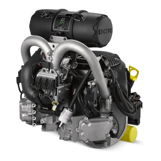
Kohler Command Pro ECV850 Service Manual (105 pages)
Kohler Command Pro Engines Service Manual
Brand:
Kohler
| Category:
Engine
| Size: 9 MB
Table of Contents
Contents
1
Safety Precautions
2
Maintenance Instructions
3
Maintenance Schedule
3
Every 100 Hours or Annually
3
Every 150 Hours
3
Oil Recommendations
4
Storage
4
Fuel Recommendations
4
Engine Dimensions-Flywheel Side
5
Specifications
5
Specifications
6
Engine Dimensions-Oil Filter Side
6
Engine Dimensions-Engine Mounting Surface (PTO End)
7
Engine Dimensions-Valve Cover Side
8
Engine Identification Numbers
9
General Specifications
9
Torque Specifications
9
Blower Housing
9
Intake Manifold, Air Cleaner, Throttle Body
10
Connecting Rod
10
Crankcase
10
Cylinder Head
10
Governor (Electronic)
11
Governor (Mechanical)
11
Ignition
11
Muffler
11
Clearance Specifications
12
Crankshaft
12
General Torque Values
15
English Fastener Torque Recommendations for Standard Applications
15
Metric Fastener Torque Recommendations for Standard Applications
15
Tools and Aids
16
Separate Tool Suppliers
16
Flywheel Holding Tool
18
Rocker Arm/Crankshaft Tool
18
Troubleshooting Guide
19
Engine Cranks but will Not Start
19
Engine will Not Crank
19
Engine Runs but Misses
19
Engine Loses Power
20
Engine Uses Excessive Amount of Oil
20
Oil Leaks from Oil Seals, Gaskets
20
External Engine Inspection
20
Crankcase Vacuum Test
21
To Test Crankcase Vacuum with Manometer
21
To Test Crankcase Vacuum with Vacuum/Pressure Gauge
21
Compression Test
22
Cylinder Leakdown Test
22
For Command Twins
22
All Other Models
22
Breather Tube
23
Air Cooling
23
Air Cleaner/Intake
23
Efi System
24
Fuel Line
24
Fuel Recommendations
24
Operation
24
Important Notes
27
Electrical Components
28
Electronic Control Unit (ECU)
28
Pinout of ECU
28
TPS Learn Procedure
29
ECU Reset Procedure
29
Wiring Diagram Electronic Governor
30
Wiring Diagram Mechanical Governor
31
Crankshaft Position Sensor
32
Replace Magnet Assembly
32
Throttle Position Sensor (TPS)
32
Engine (Oil) Temperature Sensor
33
Temperature/Manifold Air Pressure (TMAP) Sensor
33
Oxygen Sensor
34
Cutaway Oxygen Sensor Components
34
Sensor Signal Observation
34
Visual Inspection
34
Removal Inspection
35
Fuel Injectors
36
Details
36
Fuel Components
37
Ignition Coils
37
Fuel Pump Module (FPM)
37
Testing
37
High Pressure Fuel Line
38
Purge Port and Vent Hose Assembly
38
Throttle Body/Intake Manifold Assembly
38
Troubleshooting
38
Function Test
40
Fault Codes
40
Example of Diagnostic Display
40
Diagnostic Fault Code Summary
40
Diagnostic Code Summary
41
Code 0031
41
Code 0032
41
Code 0107
42
Code 0108
42
Code 0113
42
Code 0117
42
Code 0122
43
Code 0131
43
Code 0123
43
Code 0132
43
Code 0171
44
Code 0172
44
Maximum Adaptation Limit Exceeded
44
Minimum Adaptation Limit Exceeded
44
Code 0174
45
Code 0202
45
Code 0230
45
Code 0201
45
Code 0336
46
Code 0351
46
Code 0337
46
Code 0352
46
Code 1693
47
Code 1694
47
Code 61
47
Troubleshooting Flow Chart
47
EFI Diagnostic Flow Diagram
48
Start of Test
48
Electronic Governor
49
Digital Linear Actuator (DLA)
49
Linkage
49
Governor System
49
Adjustment
50
Gcu/Harness Diagnostics and Troubleshooting
50
Ground and Power Tests
50
Test 1 Probe Location
50
Test 2 Probe Location
51
Ohms Tests
51
Speed Control Input
51
GCU Blink Code Tests
52
Electronic Governor Troubleshooting Flow Chart
54
Turn off Key Switch
54
Mechanical Governor
57
Inside Engine
57
Governor Adjustments
58
Lubrication Components
59
Check Oil Level
59
Change Oil and Filter
59
Lubrication System
59
Installation
60
Normally Closed Switch
60
Oil Sentry
60
Oil Cooler
60
Spark Plugs
61
Spark Plug Component and Details
61
Electrical System
61
Battery
62
Battery Size Recommendations
62
Battery Maintenance
62
Battery Test
62
Battery Charging System
63
20/25 Amp Regulated Charging System
63
Stator
63
Rectifier-Regulator
63
20/25 Amp Battery Charging System
64
To Test Charging System for no Charge to Battery
64
Fuses
65
Fuse Replacement
65
Starter System
66
Troubleshooting-Starting Difficulties
66
Solenoid Shift Starters
67
Starter Disassembly
67
Solenoid Shift Starter Components
67
Drive Pinion
67
Armature
68
Components and Details
68
Starter Reassembly
68
Brush Replacement
68
Solenoid Tests
69
To Test Solenoid Pull-In Coil/Plunger
69
To Test Solenoid Hold-In Coil
69
External Engine Components
70
Disassembly/Inspection and Service
70
Disassembly/Inspection and Service
71
Disconnect Spark Plug Leads
71
Drain Oil from Crankcase and Remove Oil Filter
71
Disconnect Wire Harness
71
Remove Governor Linkages, Spring, and Lever
72
Remove Manifold Assembly
72
Remove Oil Cooler
72
Mechanical Governor Components
72
Blower Housing/Starter Motor/Fuel Pump Module Components
73
Remove Fuel Pump Module (FPM)
74
Remove Starter Motor
74
Remove Fixed Guard
74
Remove Debris Screen
74
Remove Baffles/Wire Harness/Stator Components
75
Remove Valley Baffle
75
Remove Cylinder Baffles
75
Remove Stator
75
Remove Breather Assembly
76
Breather Assembly Components
76
Cylinder Head Components
77
Remove Valve Covers
77
Remove Spark Plugs
77
Remove Cylinder Heads
77
Inspection and Service
78
Valve Details
78
Exhaust Valve
78
Valve Guides
79
Lapping Valves
79
Valve Stem Seals
79
Valve Seat Inserts
79
Remove Oil Pan Assembly
80
Oil Pump Assembly
80
Remove Camshaft and Valve Tappets
81
Remove Connecting Rods with Pistons and Rings
81
Remove Governor Cross Shaft
81
Governor Cross Shaft Oil Seal
81
Piston and Rings
82
Piston and Rings Components and Details
82
Install New Piston Rings
83
Piston Ring Orientation
83
Remove Crankshaft
83
Crankshaft Components and Details
83
Clearance Specifi Cations-Connecting Rod Journal
84
Honing Detail
84
Remove Crankshaft Plug
84
Remove Flywheel End Oil Seal
84
Clean Cylinder Bore after Honing
85
Measuring Piston-To-Bore Clearance
85
Piston Detail
85
Intake Manifold and Throttle Body Assembly Components
86
Remove Throttle Body
87
Remove GCU (Electronic Governor)
87
Remove Ignition Coils
87
Fuel Pump Assembly Components
87
Crankcase Components
88
Install Flywheel End Oil Seal
88
Install Governor Cross Shaft (Mechanical Governor)
88
Install Crankshaft
88
Install Connecting Rods with Pistons and Rings
89
Install Valve Tappets and Camshaft
89
Connecting Rod Torque Sequence
89
Determining Camshaft End Play
89
Governor Assembly
90
Install Oil Pan Seal
90
Install Oil Pan Assembly
90
Check Crankshaft End Play
90
Assemble Cylinder Heads
91
Install Cylinder Heads
92
Adjust Valve Clearance
92
Torque Sequence
92
Install Guide Plate, Rocker Arm Pivot, Push Rods and Rocker Arms
92
Install Valve Covers
93
Install Breather Assembly
93
Baffles/Wire Harness/Stator Components
94
Install Valley, Crankcase, and Cylinder Baffles
94
Install Stator and Wire Harness
94
Install Oil Temperature Sensor
95
Install Flywheel/Fan
95
Install Oil Sentry Pressure Switch
95
Install Crankshaft Position Sensor
95
Blower Housing/Starter Motor/Fuel Pump Components
96
Install Blower Housing
97
Install Metal Debris Screen
97
Install Fixed Guard
97
Install Starter Motor
97
Install Oil Cooler
99
Install Throttle Body Bracket
99
Install Intake Manifold/Throttle Body Assembly
99
Initial Adjustment Procedure
100
Install Oil Filter and Add Oil to Crankcase
100
Install Spark Plugs
100
Connect Spark Plug Leads
100
Testing Engine
101
Advertisement
Advertisement
Related Products
Kohler Command PRO ECV980
Kohler Command PRO ECV940
Kohler Command Pro ECV880
Kohler Command Pro ECV860
Kohler Command Pro ECV870
Kohler Command PRO CV732
Kohler Command PRO CV742
Kohler Command PRO CH752
Kohler Command PRO CV730
Kohler Command Pro CV200
Kohler Categories
Plumbing Product
Bathroom Fixtures
Toilets
Bathtubs
Engine
More Kohler Manuals
Login
Sign In
OR
Sign in with Facebook
Sign in with Google
Upload manual
Upload from disk
Upload from URL