Sign In
Upload
Manuals
Brands
Keysight Manuals
Multimeter
U3606B
Keysight U3606B Manuals
Manuals and User Guides for Keysight U3606B. We have
4
Keysight U3606B manuals available for free PDF download: User Manual, Service Manual, Quick Start Manual
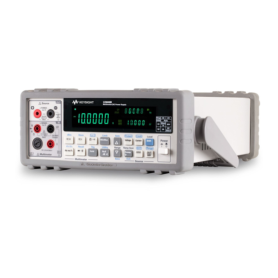
Keysight U3606B User Manual (210 pages)
Multimeter/DC Power Supply
Brand:
Keysight
| Category:
Multimeter
| Size: 6 MB
Table of Contents
Restricted Rights Legend
4
Safety Symbols
5
Environmental Conditions
7
Table of Contents
11
1 Introduction
20
About this Manual
20
Documentation Map
20
Safety Notes
20
Preparing the U3606B
21
Check the Shipment
21
Connect Power to the Instrument
23
Adjust the Carry Handle
25
Rack Mount the Instrument
26
Figure 1-1 Single Rack Mounted U3606B
26
Figure 1-2 Two U3606B Rack Mounted Side-By-Side
26
Figure 1-3 Rack Mount Dimensions
27
Stack Multiple U3606B Units
28
The U3606B in Brief
29
Dimensions
29
Figure 1-4 U3606B Dimensions
29
Overview
30
Figure 1-5 the Front Panel at a Glance
30
Table 1-1 Front Panel Descriptions
30
Figure 1-6 the Rear Panel at a Glance
31
Table 1-2 Rear Panel Descriptions
32
Display Screen
33
Figure 1-7 the VFD Display at a Glance
33
Table 1-3 VFD Display Descriptions
33
Keypad
36
Figure 1-8 the Keypad at a Glance
36
Table 1-4 Keypad Descriptions
37
Input/Output Terminals
42
Figure 1-9 the Input/Output Terminals at a Glance
42
Table 1-5 Input Terminal Connections
43
Table 1-6 Output Terminal Connections
44
2 Operation and Features
48
Measuring Voltage
48
Table 2-1 Voltage Measurement Summary
49
Measuring Current
51
Table 2-2 Current Measurement Summary
52
Measuring Resistance
54
Table 2-3 Resistance Measurement Summary
56
Testing Continuity
57
Table 2-4 Continuity Test Summary
59
Measuring Low-Resistance
60
Table 2-5 Low-Resistance Measurement Summary
62
Table 2-6 Low-Resistance Test Current Values
63
Measuring Capacitance
65
Table 2-7 Capacitance Measurement Summary
67
Testing Diodes
68
Table 2-8 Diode Test Summary
70
Measuring Frequency/Pulse Width/Duty Cycle (Voltage Path)
71
Table 2-9 Frequency/Pulse Width/Duty Cycle Measurement (Voltage Path) Summary
73
Measuring Frequency/Pulse Width/Duty Cycle (Current Path)
74
Table 2-10 Frequency /Pulse Width/Duty Cycle Measurement (Current Path) Summary
76
Selecting a Range
77
Setting the Resolution
79
Math Operations
80
Table 2-11 Math Operations Summary
80
Null
81
Dbm Measurements
84
Db Measurements
85
Minmax
87
Limit
88
Hold
91
Triggering the Multimeter
93
Front Panel Triggering
94
Remote Interface Triggering
95
600 DC Power Supply Operation
98
Constant Voltage Operation
98
Constant Current Operation
101
Protection Functions
104
Over-Voltage Protection (OVP)
104
Table 3-1 CC Mode Over-Voltage Protection Range and Values
106
Over-Current Protection (OCP)
108
Table 3-2 CV Mode Over-Current Protection Range and Values
110
Over-Voltage Limit (OV)
112
Table 3-3 CC Mode Over-Voltage Range and Values
114
Over-Current Limit (OC)
115
Table 3-4 CV Mode Over-Current Range and Values
117
Square-Wave Operation
118
Table 3-5 Square-Wave Amplitude Minimum and Maximum
123
Sweep Functions
124
Ramp Signal
124
Scan Signal
127
Selecting a Range
131
Table 3-6 Available Ranges for DC Power Supply Functions
131
Enabling the Output
132
Remote Sensing
133
Figure 3-1 Remote Sensing Connections
134
Figure 3-2 Local Sensing Connections
134
4 System-Related Operation
141
Using the Utility Menu
142
Utility Menu Summary
144
Table 4-1 Utility Menu Summary
144
Utility Menu Items
147
Reading Error Messages
147
Configuring the Data Logging Parameters
148
Recording Measurement Data (Data Logging)
149
Enabling Refresh Hold
150
Setting the Smooth Function
151
Configuring the Scan Signal Parameters
154
Table 4-2 Scan Signal Parameters
154
Configuring the Ramp Signal Parameters
156
Table 4-3 Ramp Signal Parameters
156
Setting the Output Protection State
158
Table 4-4 System Protection Values
158
Adjusting the Soft Start Output
159
Selecting a Dbm Reference Resistance Value
160
Performing a Self-Test
160
Connecting to a Remote Interface
161
Configuring the Beeper
162
Changing the Power-On State
163
Adjusting the Display Brightness
164
Reading the Program Code Revision
164
Storing and Recalling Instrument States
165
Storing a State
166
Recalling a Stored State
167
Remote Operation
168
Configuring and Connecting the GPIB Interface
169
Configuring and Connecting the USB Interface
170
SCPI Commands
170
5 Characteristics and Specifications
173
Product Characteristics
174
Digital Multimeter Specifications
176
Specification Assumptions
176
DC Specifications
177
Table 5-1 DC Accuracy Specifications
177
AC Specifications
181
Table 5-2 AC Accuracy Specifications
181
Frequency Specifications
183
Table 5-4 Frequency Sensitivity for Voltage Measurement
184
Table 5-5 Frequency Sensitivity for Current Measurement
184
Duty Cycle and Pulse Width Specifications
185
Operating Specifications
185
Table 5-6 Duty Cycle and Pulse Width Resolution and Accuracy
185
Table 5-7 Reading Speed (Typical)
185
Supplemental Characteristics
187
DC Power Supply Specifications
193
Safety Considerations
193
Specifications Assumptions
193
Performance Specifications
194
Table 5-8 DC Power Supply Performance Specifications
194
Supplemental Characteristics
196
Table 5-9 DC Power Supply Supplemental Characteristics
196
Table 5-10 Square-Wave Output Characteristics
197
Table 5-11 Scan Output Characteristics
199
Table 5-12 Ramp Output Characteristics
199
Sweep Characteristics
199
Command Errors 183
201
Error Messages
201
6 List of Error Messages
202
Error Messages
202
Table 6-1 List of Command Errors
203
Execution Errors
204
Self-Test Errors
204
Table 6-2 List of Execution Errors
204
Device Specific Errors
205
Internal Errors
205
Query Errors
205
Table 6-3 List of Internal Errors
205
Table 6-4 List of Query Errors
205
Table 6-5 List of Device Specific Errors
205
Table 6-6 List of Self-Test Errors
206
Calibration Errors
207
Table 6-7 List of Calibration Errors
207
Advertisement
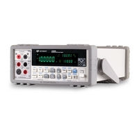
Keysight U3606B User Manual (181 pages)
Multimeter/DC Power Supply
Brand:
Keysight
| Category:
Power Supply
| Size: 8 MB
Table of Contents
Copyright Notice
2
Declaration of Conformity
2
Safety Symbols
3
Safety Considerations
4
Environmental Conditions
6
Regulatory Markings
7
Waste Electrical and Electronic Equipment (WEEE) Directive 2002/96/EC
8
Product Category
8
Sales and Technical Support
8
Table of Contents
9
List of Tables
15
Safety Information
2
1 Introduction
17
About this Manual
18
Documentation Map
18
Safety Notes
18
Preparing the U3606B
19
Check the Shipment
19
Connect Power to the Instrument
21
Adjust the Carry Handle
23
Rack Mount the Instrument
24
Rack Mount Dimensions
25
Stack Multiple U3606B Units
26
The U3606B in Brief
27
Dimensions
27
Overview
28
Table 1-1 Front Panel Descriptions
28
The Rear Panel at a Glance
29
Table 1-2 Rear Panel Descriptions
30
Display Screen
31
Table 1-3 VFD Display Descriptions
31
Keypad
34
Table 1-4 Keypad Descriptions
36
Input/Output Terminals
40
Table 1-5 Input Terminal Connections
41
Table 1-6 Output Terminal Connections
42
2 Operation and Features
46
Measuring Voltage
46
Table 2-1 Voltage Measurement Summary
48
Measuring Current
50
Table 2-2 Current Measurement Summary
51
Measuring Resistance
53
Table 2-3 Resistance Measurement Summary
55
Testing Continuity
56
Table 2-4 Continuity Test Summary
58
Measuring Low-Resistance
59
Table 2-5 Low-Resistance Measurement Summary
61
Table 2-6 Low-Resistance Test Current Values
62
Measuring Capacitance
64
Table 2-7 Capacitance Measurement Summary
66
Testing Diodes
67
Table 2-8 Diode Test Summary
69
Measuring Frequency/Pulse Width/Duty Cycle (Voltage Path)
70
Table 2-9 Frequency/Pulse Width/Duty Cycle Measurement (Voltage Path) Summary
72
Measuring Frequency/Pulse Width/Duty Cycle (Current Path)
73
Table 2-10 Frequency /Pulse Width/Duty Cycle Measurement (Current Path) Summary
75
Selecting a Range
76
Setting the Resolution
77
Math Operations
78
Table 2-11 Math Operations Summary
78
Null
79
Dbm Measurements
82
Db Measurements
83
Minmax
85
Limit
86
Hold
89
Triggering the Multimeter
91
Front Panel Triggering
92
Remote Interface Triggering
93
600 DC Power Supply Operation
96
Constant Voltage Operation
96
Constant Current Operation
101
Protection Functions
105
Over-Voltage Protection (OVP)
105
Over-Current Protection (OCP)
108
Over-Voltage Limit (OV)
112
Table 3-1 CC Mode Over-Voltage Protection Range and Values 107 Table 3-2 CV Mode Over-Current Protection Range and Values .111 Table 3-3 CC Mode Over-Voltage Range and Values
115
Over-Current Limit (OC)
116
Table 3-4 CV Mode Over-Current Range and Values
118
Square-Wave Operation
119
Table 3-5 Square-Wave Amplitude Minimum and Maximum Values
124
Sweep Functions
125
Ramp Signal
125
Scan Signal
128
Selecting a Range
132
Table 3-6 Available Ranges for DC Power Supply Functions
132
Enabling the Output
133
Remote Sensing
134
Remote Sensing Connections
135
Output Rating
140
System-Related Operation
141
4 System-Related Operation
142
Using the Utility Menu
142
Utility Menu Summary
144
Table 4-1 Utility Menu Summary
144
Utility Menu Items
147
Reading Error Messages
147
Configuring the Data Logging Parameters
148
Recording Measurement Data (Data Logging)
148
Enabling Refresh Hold
149
Setting the Smooth Function
151
Configuring the Scan Signal Parameters
154
Table 4-2 Scan Signal Parameters
154
Configuring the Ramp Signal Parameters
156
Table 4-3 Ramp Signal Parameters
156
Setting the Output Protection State
158
Table 4-4 System Protection Values
158
Adjusting the Soft Start Output
159
Selecting a Dbm Reference Resistance Value
159
Performing a Self-Test
160
Connecting to a Remote Interface
161
Configuring the Beeper
161
Changing the Power-On State
162
Adjusting the Display Brightness
163
Reading the Program Code Revision
163
Storing and Recalling Instrument States
164
Storing a State
165
Recalling a Stored State
166
Remote Operation
167
Configuring and Connecting the GPIB Interface
168
Configuring and Connecting the USB Interface
169
SCPI Commands
169
5 Characteristics and Specifications
171
5 Characteristics and Specifications
172
6 List of Error Messages
173
Error Messages
174
Command Errors
175
Table 6-1 List of Command Errors
175
Execution Errors
176
Table 6-2 List of Execution Errors
176
Internal Errors
177
Query Errors
177
Device Specific Errors
177
Table 6-3 List of Internal Errors
177
Table 6-4 List of Query Errors
177
Self-Test Errors
178
Calibration Errors
179
Keysight U3606B Service Manual (123 pages)
Multimeter | DC Power Supply
Brand:
Keysight
| Category:
Multimeter
| Size: 8 MB
Table of Contents
Safety Symbols
3
Safety Considerations
4
Environmental Conditions
5
Regulatory Markings
6
Waste Electrical and Electronic Equipment (WEEE) Directive 2002/96/EC
7
Product Category
7
Sales and Technical Support
7
Table of Contents
9
1 Calibration Procedures
18
Calibration Overview
18
Closed-Case Calibration
18
Keysight Calibration Services
18
Calibration Interval
18
Adjustment Is Recommended
19
Time Required for Calibration
19
Recommended Test Equipment
20
General Measurement Techniques
23
Using an Electronic Load
24
Connecting the Current Monitoring Resistor
24
Test Considerations
25
Input and Output Connections
26
Zero Offset (Short) Verification Test Setup
27
Figure 1-1 Test Setup for Zero Offset (Short) Verification
27
Gain Verification Test Setup
28
Figure 1-2 Test Setup for DC Voltage and AC Voltage Gain
28
Figure 1-3 Test Setup for Capacitance Gain Verification
29
Figure 1-4 Test Setup for 2-Wire Resistance Gain Verification
30
Figure 1-5 Test Setup for 4-Wire Resistance Gain Verification
31
Figure 1-6 Test Setup for DC Current and AC Current Gain
31
Figure 1-7 Test Setup for Frequency Voltage Gain Verification
32
Figure 1-8 Test Setup for Frequency Current Gain Verification
32
Figure 1-9 Test Setup for Diode Voltage Gain Verification
33
Output Verification Test Setup
34
Figure 1-10 Test Setup for Constant Voltage Programming and Readback Accuracy Verification
34
Figure 1-11 Test Setup for Constant Voltage Load and Line Regulation Verification
34
Figure 1-12 Test Setup for Constant Voltage Noise Effect (Peak-To-Peak and RMS Noise) Verification
35
Figure 1-13 Test Setup for Load Transient Response Time Verification
35
Figure 1-14 Test Setup for Constant Current Programming and Readback Accuracy Verification
36
Figure 1-15 Test Setup for Constant Current Load and Line Regulation Verification
36
Figure 1-16 Test Setup for Constant Current RMS Noise Effect
37
Performance Verification Tests Overview
38
Self-Tests
39
Performance Verification Tests
40
Zero Offset Verification Test
40
Gain Verification Test
42
Output Verification Test
48
Figure 1-17 Graph of Load Transient Response Time for S1 Range
55
Additional Verification Tests
62
Optional Capacitance Gain Verification Test
62
Calibration Process
64
Calibration Security
65
Unsecuring the Instrument for Calibration
66
Unsecuring the Instrument from the Front Panel
66
Unsecuring the Instrument from the Remote Interface
68
Changing the Calibration Security Code
68
Resetting the Security Code to the Factory Default
69
Figure 1-18 SECUR Pads Location
70
Using the Front Panel for Adjustments
72
Adjustment Considerations
73
Aborting a Calibration in Progress
74
Adjustments Procedures
75
Zero Offset Adjustment
75
Gain Adjustments
76
Output Adjustments
89
Finishing the Adjustments
99
Calibration Count
100
Calibration Message
101
Calibration Error Codes
102
2 Service and Maintenance
106
Operating Checklist
106
Cleaning
107
Fuse Replacement
108
To Replace the Power Line Fuse
108
To Replace the Current Input Fuse
110
Electrostatic Discharge (ESD) Precautions
112
Mechanical Disassembly
113
General Disassembly
113
Replaceable Parts
120
To Order Replaceable Parts
120
Types of Services Available
121
Repackaging for Shipment
122
Advertisement
Keysight U3606B Quick Start Manual (23 pages)
Multimeter / DC Power Supply
Brand:
Keysight
| Category:
Power Supply
| Size: 2 MB
Table of Contents
Safety Symbols
3
Environmental Conditions
4
Regulatory Markings
5
Additional Safety Information
6
Table of Contents
7
Standard Shipped Items
9
The Front Panel at a Glance
10
The Display at a Glance
11
Power-On the U3606B
12
Adjust the Carrying Handle
13
Connect the Test Leads to the Terminals
14
Select a Function
17
Where to Go Next
21
User References
21
Keysight Support and Contact Information
21
Advertisement
Related Products
Keysight U3606A
Keysight U3401A
Keysight U1251B
Keysight U1252B
Keysight U1270 Series
Keysight U1272A
Keysight U1232A
Keysight u1273a
Keysight u1273ax
Keysight U2741A
Keysight Categories
Measuring Instruments
Test Equipment
Multimeter
Portable Generator
Power Supply
More Keysight Manuals
Login
Sign In
OR
Sign in with Facebook
Sign in with Google
Upload manual
Upload from disk
Upload from URL