Sign In
Upload
Manuals
Brands
Keysight Technologies Manuals
Test Equipment
PD1500A
Keysight Technologies PD1500A Manuals
Manuals and User Guides for Keysight Technologies PD1500A. We have
4
Keysight Technologies PD1500A manuals available for free PDF download: Software Manual, System Installation Manual, Installation And Use Manual, Operation And Maintenance
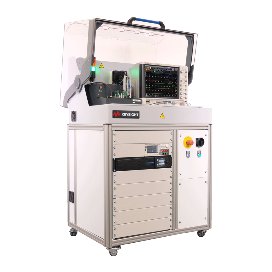
Keysight Technologies PD1500A Software Manual (146 pages)
Dynamic Power Device Analyzer/Double-Pulse Tester
Brand:
Keysight Technologies
| Category:
Test Equipment
| Size: 3 MB
Table of Contents
Table of Contents
9
Introduction
13
In this Chapter
13
Double-Pulse Test Overview
14
Test Equipment and Accessories Used in the PD1500A
16
PD1500A Double-Pulse Test Documentation
18
Host Computer System Requirements
19
System Installation and Support
19
Software Installation
21
Install Software on Host PC
22
Install Keysight IO Libraries Suite on Your Host PC
22
Download PD1000A Control Software
22
Software Licensing
22
Set-Up the Double-Pulse Test for Si/Sic Devices
25
Test Circuit Diagrams
25
Test Fixture Modules for Si/Sic Devices
28
Connect Probes to DSOS104A or MXR108A Oscilloscope
30
Connect Probes to the Double-Pulse Test Modules
33
Using the N2787A 3D Probe Positioner
35
Connect the 10076C High Voltage Probe
36
Double-Pulse Test Device Characterization Tests
37
Testing Gan Devices
37
Obtain Oscilloscope IP Address
38
Settings in the PD1000A Control Software
39
Global Settings
39
Hardware Configuration for Double-Pulse Test Control
40
Load Settings from File
40
Save Settings to File
40
Calibration & Compensation
41
Show Oscilloscope Screen
41
Show Log
41
About
41
Hardware Configuration for Double-Pulse Test Control
42
DPT System PD1500A Tab
42
Fixture Tab
44
Oscilloscope Tab
46
Calibration Tab
48
Measurement Preparation - Calibration & Compensation
49
EEPROM Migration
49
Oscilloscope Probe Compensation
49
PD1500A System Calibration
49
Oscilloscope Probe Deskew
49
Coaxial Current Shunt De-Embedding
50
Standard Double-Pulse Characterization Test
51
Use These Double-Pulse Test Modules and Oscilloscope Probes
51
Clamped Double-Pulse Test
53
Use These Double-Pulse Test Modules and Oscilloscope Probes
53
Reverse Recovery Test
55
Use These Double-Pulse Test Modules and Oscilloscope Probes
55
Set Double-Pulse Test Parameters
56
Gate Resistance
57
Custom Inductor Value
57
DUT Parameters
58
Clamp Output Screen
63
Measurement Parameters for Standard, Clamp, and Reverse Tests
64
Control Signal
64
Gs Ge
64
GS or
64
Or VGE ))
64
Output Voltage (V Ds or V Ce )
65
Output Current (I Ds or I Ce )
66
Run the Characterization Test
67
Results Tab
69
Measurement History Tab
70
Measurement History Columns
70
Using Filters
70
Additional Features of the Measurement History
71
Frequently Asked Questions
74
APD1500A System Specifications
77
How to Use this Specification Chapter
82
Technical Specification and Characteristics
82
Additional Information
82
IMPORTANT - Calibration Information
84
General Purpose ±28 V Gate Drive Modules Calibration
84
Gan Test Board Calibration
84
Set/Verify AC Line Frequency & Date/Time on
84
Set/Verify AC Line Frequency & Date/Time
84
Begin Calibration & Compensation
85
Oscilloscope Probe Compensation
86
Required Equipment
86
Low Frequency Compensation for the 10076C and N2873A Probes
86
Offset Compensation for the N2819A Differential Probe
87
Si/Sic System Calibration Procedure (Autocal)
89
±28 V Gate Modules
90
Gate Voltage Calibration - V
91
Gs /Vge
91
Gate Voltage Calibration - V
92
GS /V GE Probe: ±28 V Gate Drive Modules
92
Modules
93
GS /VGE Output: Standard Gate Drive
93
Gate Voltage Source Calibration - V
93
GS GE Probe: ±28 V Gate Drive
93
Gate Drive Modules
93
GS /VGE Output: Standard
93
Modules
94
GS /VGE Output: ±28 V Gate Drive
94
Gate Voltage Source Calibration - VGS /VGE Output: ±28 V Gate
94
Drive Modules
94
Gate Current Calibration - I G Probe: Standard Gate Drive Modules
95
Gate Current Calibration - I Probe: Standard Gate Drive Modules
95
Gate Current Calibration - I G Probe: ±28 V Gate Drive Modules
96
Gate On-Resistance Calibration - R G Value: Standard Gate Drive
97
Modules
97
Gate On-Resistance Calibration - R G Value: ±28 V Gate Drive Modules
98
Gate On-Resistance Calibration - R G Value: ±28 V Gate Drive
98
Gate Off-Resistance Calibration - R (Split-Path R G,OFF )
99
G Value: ±28 V Gate Drive Modules
99
Gate Off-Resistance Calibration - R G Value: ±28 V Gate Drive
99
G,Off
99
High Voltage Probe Calibration - V
100
DS CE Probe
100
Clamp Circuit Probe Calibration
101
CLAMP Probe
101
PD1000-60002 Protection Probe Calibration - I from Shunt
102
D /I C
102
Oscilloscope Probe Deskew
103
Connect Probes to Deskew Fixture
103
Initializing PD1000-66848 and -66849 Modules for Calibration
105
EEPROM Values for Split-Path Gate Drive Modules
109
Coaxial Shunt Resistor Characterization
110
C Using the Optional Device Heaters
111
Configuring Temperature Control Settings
112
Activating the Heater and Setting Test Temperatures
113
Adding Kapton (Polyimide) Tape to TO-247-3 and -4 Devices
114
Using the Talenia Electronics High-Side Device Heater
115
Installation of Talenia Electronic PD1500-HHU1
117
Setting the Temperature in the PD1000A Control Software
117
Talenia Model PD1500-HHU1 Specifications
117
Device Heater Theory of Operation
118
Heater Stability
119
Using the Device Heater
119
D Update PD1500A Test Fixture Firmware
121
Identify Current Version of Test Fixture Firmware
121
Firmware Update Process
124
ESMA Connectors
127
Final Connection Using a Torque Wrench
128
Separating Connections
129
Inspect and Clean Connectors
130
F Measurement Tips and Troubleshooting
131
Typical Problems
132
Error Messages
133
Problem: Error Message Occurs
133
Voltage and Supply Voltage (VDS )
133
Problem: Error Message -- One or more Extractions Failed
133
Problem: Error Message -- Failed to Generate IV Derivation
133
Problem: Drain Voltage
134
DS ) Goes Negative and then very High
134
Problem: Loose Shunt Resistor Connection
135
Problem: Error Related to Oscilloscope Channel 1
136
Problem: High-Side Device Is Broken
136
For Gan Devices
137
Problem: on Reverse Recovery, Avoiding Unnecessary "Hump
137
Problem: Inductor Not Connected Properly
138
A Technique to Create an Accurate High-Power IV Curve
139
Index
141
Advertisement
Keysight Technologies PD1500A System Installation Manual (108 pages)
Double-Pulse Test Rack and Safety Enclosure
Brand:
Keysight Technologies
| Category:
Enclosure
| Size: 3 MB
Table of Contents
Table of Contents
9
Site Preparation
14
Customer Responsibilities
14
Rack and Safety Enclosure Dimensions and Weight
14
Tools Supplied for Installation and Instrument Removal
14
Double-Pulse Test Rack and Safety Enclosure Location
15
Electrical and Environmental Requirements
16
Connect the DPT Rack and Safety Enclosure to AC Mains
16
AC Power Cord
16
Mains Disconnect
17
Optional Safety Ground Connection
17
Receiving the Rack and Safety Enclosure and Test Instruments
18
Moving the Rack and Safety Enclosure
18
Inventory the Shipment
19
Host Computer System Requirements
21
Static-Safe Handling Procedures
21
Simplified System Diagrams
23
Uncrate the Rack and Safety Enclosure
25
Uncrate the Rack and Safety Enclosure
26
Moving the Rack and Safety Enclosure
27
Rack and Safety Enclosure System Hardware Components
28
Re-Crating the Rack and Safety Enclosure for Shipping
29
Install Oscilloscope in Safety Enclosure Hood
31
Prepare the Rack and Safety Enclosure
31
Install Oscilloscope Inside the Safety Hood
32
Connect LAN, Power, and Trigger Cables to the Oscilloscope
33
Connect Probes to DSOS104A or MXR108A Oscilloscope
35
Connect Probes to the Double-Pulse Test Modules
38
Using the N2787A 3D Probe Positioner
40
Install Test Fixture in the Safety Enclosure Hood
43
Placing the Test Fixture in the Safety Enclosure Hood
44
Connections on Back of Test Fixture
45
Connect the Waveform Generator to the DPT Test Fixture
46
Connections on Front of Test Fixture
46
Optional Low-Side Device Heater
47
Second Thermocouple Jack on Test Fixture
47
Thermocouple
47
TO-247 Devices
47
Using the Low-Side Device Heater and Thermocouple
47
Adding Kapton (Polyimide) Tape to TO-247-3 and -4 Devices
49
Device Heater Theory of Operation
49
Configuring Temperature Control Settings (Hardware Configuration)
51
Mounting the Coaxial Shunt Resistor
54
Identify Test Fixture Firmware Version
55
Turn-On and Software Installation
57
Double-Pulse Test System Turn-On and Turn-Off
58
Step 1: Connect LAN and Power Cable to Rack
58
Turn-On and Software Installation
58
Emergency off Functionality
59
Light Tower Inside the Safety Hood
59
Turning the System off
59
Download PD1000A System Control Software
60
Install IO Libraries Suite on Host PC
60
Step 2: Install System Software on Host PC
60
Software Licensing
61
Step 3: Set Oscilloscope VISA Address
62
Instrument Verification
63
More about IP Addresses and Dot Notation
63
Set AC Line Frequency and Date/Time on the B2902 SMU
63
Step 4: Obtain and Install Coaxial Shunt Resistor De-Embedding File
64
Verify D9020ASIA License on the Oscilloscope
64
Annual Characterization of the Coaxial Shunt
65
Obtain the Shunt De-Embedding File
65
Install the De-Embedding Transfer File on the Oscilloscope
66
Si/Sic Autocalibration
67
PD1500A Double-Pulse Test Si/Sic Autocalibration
67
Initiate Calibration & Compensation Procedures
68
Low Frequency Compensation for the 10076C and N2873A Probes
69
Oscilloscope Probe Compensation
69
Required Equipment
69
Offset Compensation for the N2819A Differential Probe
70
Requirements
72
Si/Sic System Calibration Procedure (Autocal)
72
Module Initialization
73
±28 V Gate Modules
73
Gate Voltage Calibration - V
74
System Calibration Procedure (Autocal)
74
Gate Voltage Calibration - V
75
Gs /Vge
75
GS GE Probe: ±28 V Gate Drive Modules
75
Gate Voltage Source Calibration - V
76
Gs /Vge
76
Modules
76
Gate Voltage Source Calibration - V
77
GS /VGE Output: ±28 V Gate Drive
77
Modules
77
Gate Current Calibration - I G Probe: Standard Gate Drive Modules
78
Gate Current Calibration - I G Probe: ±28 V Gate Drive Modules
79
Drive Modules
80
Gate On-Resistance Calibration - R G Value: Standard Gate
80
Gate On-Resistance Calibration - R G Value: Standard Gate Drive Modules82 Gate On-Resistance Calibration - R G Value: ±28 V Gate Drive Modules
81
Probe
81
(Split-Path R G,OFF )
82
Gate Off-Resistance Calibration - R G Value: ±28 V Gate Drive Modules
82
Ds /Vce
83
High Voltage Probe Calibration - V
83
Clamp Circuit Probe Calibration
84
CLAMP Probe
84
PD1000-60002 Protection Probe Calibration - I D /I C from Shunt
85
PD1000-60002 Protection Probe Calibration - I from Shunt
85
Connect Probes to Deskew Fixture
86
Oscilloscope Probe Deskew
86
Initializing PD1000-66848 and -66849 Modules for Calibration
88
Initialize New Data Eeproms for Split-Path Gate Drive Module
89
EEPROM Values for Split-Path Gate Drive Modules
92
Coaxial Shunt Resistor Characterization
93
Install the De-Embedding Transfer File on the DSOS104 Oscilloscope
93
Oscilloscope Probe Deskew
93
A Simplified System Diagrams and Schematics
95
Basic AC Power and LAN Wiring for the DPT Instruments in the Rack
96
DPT System Wiring Simplified Diagram
97
Connect Probes to DSOS104A or MXR108A Oscilloscope
98
Connect Probes to DSOS104A or MXR108A Oscilloscope Page
98
Simplified DPT Test Schematic
100
Simplified DPT Test Schematics
100
Simplified Reverse Recovery Test Schematic
101
BSMA Connectors
103
Final Connection Using a Torque Wrench
104
Separating Connections
105
Connector Cleaning
106
Inspect and Clean Connectors
106
Keysight Technologies PD1500A Installation And Use Manual (93 pages)
Brand:
Keysight Technologies
| Category:
Test Equipment
| Size: 3 MB
Table of Contents
High Voltage
6
Safety Summary
6
Dangerous Procedure Warnings
7
Safety Information
9
Table of Contents
14
General Information
18
Incoming Inspection for Double-Pulse Test Fixture and Modules
19
Preparation for Use
19
Static-Safe Handling Procedures
19
Testing Gan Devices
19
PD1000A Test Fixture for the PD1500A Double-Pulse Test Solution
20
Connections on Back of Test Fixture
20
Test Fixture Modules for Si/Sic Devices
22
Standard Double-Pulse Test Setup
26
Use These Double-Pulse Test Modules and Oscilloscope Probes
26
Clamp Test Setup
27
Use These Double-Pulse Test Modules and Oscilloscope Probes
27
Reverse Recovery Double-Pulse Test Setup
28
Use These Double-Pulse Test Modules and Oscilloscope Probes
28
Double-Pulse Test Preparation
30
PD1500A Double-Pulse Test Fixture
31
Heater and Thermocouple (Optional)
32
Second Thermocouple Jack
32
Mounting the Coaxial Shunt Resistor
33
Install Test Modules on the Main Test Fixture
34
Install Double-Pulse Test Modules on the Test Fixture in this Sequence
35
Optional Clamp Circuit Module
37
When to Use the PD1000-66505 Clamp Circuit Module
38
Using the Clamp Circuit Module
38
How the Clamp Circuit Works
38
Connect Probes to DSOS104A or MXR108A Oscilloscope
39
Connect Probes to the Double-Pulse Test Modules
42
Using the N2787A 3D Probe Positioner
44
Connect the 10076C High Voltage Probe
45
Coaxial Shunt Resistor and PD1000-60002 Protection Probe
46
Cleaning the Protection Probe
47
DUT Test Module for Si/Sic T0-247-3 and -4 Devices
49
General Module Information
49
Install Two Transistors on the TO-247-3 and -4 DUT Modules
50
Installing and Using External Inductors
52
Testing Devices with TO-220 Packaging
53
DUT Test Module for Si/Sic D
54
PAK 7-Pin Devices
54
General Information
55
D 2 PAK Devices
56
Typical 7-Pin DPAK SMD Device
56
Install Two Transistors on the Module
56
Install Device Heater and Thermocouple on SMD Device
58
Install Chip Devices on the Module
59
Optional Gate Drive Modules
60
Standard Modules
63
Installing Gate Drive Resistors on the -66540 and - 66541 Modules
65
How to Test the Gate Drive Resistor to Ensure Proper Installation
66
General Purpose ± 28 Volt Modules
67
Split-Path Vs. Common-Path Gate Drive
69
Selecting/Installing Gate Drive Resistors on the -66848/- 66849 Moduleslxvii
70
Installing Common-Path Gate Drive Resistors
72
Installing Split-Path Gate Drive Resistors
73
How to Test the Gate Drive Resistor to Ensure Proper Installation
73
EEPROM Values
74
A Using the Optional Device Heater
76
Configuring Temperature Control Settings
78
Activating the Heater and Setting Test Temperatures
78
Adding Kapton (Polyimide) Tape to TO-247-3 and -4 Devices
79
Device Heater Theory of Operation
80
Heater Stability
81
Using the Device Heater
81
B Selecting Gate Drive Resistors
84
Low Gate Resistor Values
84
High Gate Resistor Values
85
Optimal Gate Resistor Value
85
C Installing Surface-Mount Devices
90
Using a Hot Air Solder Reflow Tool
90
Advertisement
Keysight Technologies PD1500A Operation And Maintenance (32 pages)
Test Rack and Safety Enclosure
Brand:
Keysight Technologies
| Category:
Test Equipment
| Size: 0 MB
Table of Contents
Table of Contents
11
1 Introduction
13
Plan the Rack and Safety Enclosure Site Installation
15
Customer Responsibilities
15
Receiving the Rack
15
PD1500A Double-Pulse Tests System Installation Plan
16
Electrical and Environmental Requirements
17
Rack and Safety Enclosure Dimensions and Weight
17
Static-Safe Handling Procedures
18
Rack Ventilation
19
2 Operating the Rack and Safety Enclosure
21
Safety Concepts in the DPT Rack and Safety Enclosure
21
Using the Rack and Safety Enclosure
22
Main On/Off Switch
22
Light Tower Inside the Safety Hood
23
Emergency Stop
23
Operation of the Safety Hood Interlock
23
Hood Status Indicator LED on Test Fixture
23
In Case of a Power Outage
24
Manually Unlock the Safety Hood
24
Rack and Safety Enclosure Maintenance
25
Maintenance of the Safety Hood
25
Recommended Maintenance Intervals
25
3 Additional Information
27
Rack and Safety Enclosure System Hardware Components
27
Rack and Safety Enclosure System Documentation
28
Service Information
29
Advertisement
Related Products
Keysight Technologies PNA N522xB
Keysight Technologies P9241A
Keysight Technologies P9242A
Keysight Technologies P9243A
Keysight Technologies PD1000A
Keysight Technologies PNA E8364B
Keysight Technologies PNA E8361A
Keysight Technologies P9375A
Keysight Technologies P5003A
Keysight Technologies P5552A
Keysight Technologies Categories
Measuring Instruments
Test Equipment
Control Unit
Portable Generator
Power Supply
More Keysight Technologies Manuals
Login
Sign In
OR
Sign in with Facebook
Sign in with Google
Upload manual
Upload from disk
Upload from URL